Abstract
Timed Petri nets can be used for the modelling and analysis of a wide range of concurrent discrete-event systems, e.g. production systems. The present paper describes how to do so while starting from the information about the structure of a production facility and about the products usually given in production-data management systems. We describe a method for using these data to algorithmically build a Petri-net model. The timed Petri-net simulator, which was built in Matlab®, is also described. This simulator makes it possible to introduce heuristics, and in this way production operations can be scheduled. To demonstrate the applicability of our approach, we applied it to a scheduling problem in a multi-product batch plant.
1. Introduction
Any production management information system requires a detailed plan of production operations. This can be achieved with a variety of software tools that are capable of optimal or near optimal scheduling of the operations performed on different manufacturing equipment, taking into account the finite number of available resources, precedence constraints, etc.
In general, an adequate model of the production process is needed in order to derive a feasible schedule that can be realized on the available manufacturing equipment. Within the changing production environment the effectiveness of the production modelling is, therefore, a prerequisite for a successful scheduling system.
Scheduling problems are very complex and have been proven to be NP hard in many circumstances. There are several major approaches to scheduling. Among them, mathematical programming methods can produce optimal results for some systems. However, these models have to ignore many practical constraints in order to solve these problems efficiently. This is the reason why only a few real applications exist in the industrial environment. Computational-intelligence-based approaches include knowledge-based systems, genetic systems and neural networks. Knowledge-based systems have difficulty in acquiring the efficient rules and knowledge. Genetic algorithms and neural networks require considerable computation and also have formulation difficulties. Other methods, such as algebraic models and control theoretic methods, tend not to offer efficient solution methodologies. The methods based on CPM/PERT and queuing networks can provide efficient solution methodologies, but they cannot easily describe shared resources, synchronization, and lot sizes. In Citation1 a project planning tool is used for scheduling the production activities in project-oriented production. Heuristic dispatching rules Citation2,Citation3 like Shortest Processing Time (SPT) or Longest Processing Time (LPT), are commonly used in practice. Good rules are obtained on the basis of expert knowledge, which does not ensure the best solutions in different situations. They can also be developed on the basis of system simulation models. An interesting property of heuristic dispatching rules is that they can easily be used in conjunction with production models derived within the Petri-net modelling framework.
Petri nets represent a powerful graphical and mathematical modelling tool Citation4. Many different extensions of classical Petri nets exist, and these are able to model a variety of real systems. In particular, timed Petri nets can be used to model and analyse a wide range of concurrent discrete-event systems Citation5 – Citation9. Several previous studies have addressed the timed Petri-net-based analysis of discrete-event systems. Lopez Citation10, for example, deals with the simulation of the deterministic timed Petri net for both timed places and timed transitions by using the firing-duration concept of time implementation. Petri nets can be used in the design and operation of a batch process Citation11. Van der Aalst Citation12 discusses the use of Petri nets in the context of workflow management. There is a lot of literature on the applicability of PNs in the modelling, analysis, synthesis and implementation of systems in the manufacturing applications domain. For example, a survey of the research area and a comprehensive bibliography can be found in Citation13. The authors in Citation14 show that management strategies (i.e. push, pull and kanban strategies) can be appropriately modelled by means of Petri nets. Yu et al. Citation15 propose a new class of Petri nets, called Buffer nets, for modelling flexible manufacturing systems (FMSs). They present an approach that can build up a Petri net from a FMS specification language. A Petri-net model can also be used by a heuristic scheduler. Tacconi Citation16 used the discrete-event matrix state equation together with the Petri-net state equation to obtain a complete dynamical description of a production system.
A Petri-net model can be used to analyse a modelled system. Logical properties, such as operability, the absence of deadlock, safety and hazards, etc. can be analysed, verified and validated. When time is integrated into Petri-net models, quantitative performance indices, such as cycle time, production rates and resource utilization, can be derived and evaluated. With this analysis, different possible task schedules can be evaluated.
The schedules obtained using Petri-net-based approaches are event-driven and deadlock free Citation13. Their other feature is that the completion time or makespan criterion is the optimization objective. The drawbacks of an analytical approach are that a huge reachability tree is required for large, complex systems. However, this can be avoided by introducing heuristics. The speed of such an approach depends heavily on the heuristic functions that are selected, and most heuristic functions cannot guarantee the optimality of the obtained schedules. The criterion that is normally used in the search process is the makespan; it is difficult to use other criteria, such as tardiness and due dates.
A straightforward way of using the heuristic rules within a Petri-net modelling framework is to incorporate the rules for the conflict-resolution mechanism in an appropriate Petri-net simulator. Many different Petri-net simulators exist, some of them also support timed Petri nets, and they usually support random decisions to make a choice in the case of conflicts. The Petri-net toolbox for Matlab®Citation17 allows the use of priorities or probabilities to make the choice about a conflicting transition to fire. For the modelling, simulating and analysing of untimed and timed Petri nets, CPN Tools can also be used Citation18. Zhou et al. Citation19 employed a Petri-net-based branch-and-bound method to schedule flexible manufacturing systems. In their method, instead of randomly selecting one decision candidate from candidate sets, they select one based on heuristic dispatching rules, such as Shortest Processing Time (SPT). Julia Citation20 presented the simulation of a p-timed Petri net for the real-time scheduling of batch systems; a token player algorithm is applied and used for the detection of abnormal behaviours.
The information about the structure of a production facility and about the products that can be produced is usually stored in production management information systems such as Manufacturing Resource Planning (MRP II) systems. With these systems an additional scheduling tool can be appended. In this configuration the company can plan future activities while anticipating the market, but at the same time being flexible enough to handle changes in the short term Citation21. Czerwinski Citation22 proposed a method for scheduling products with the bill of the material (BOM), using an improved Lagrangian Relaxation technique. An approach presented by Citation23 maintains production data by using a bill of manufacture (BOMfr), which integrates the BOM and the routing data. Production data are then used to determine the production jobs that need to be completed in order to meet demands. Our work is based on production management systems where the product structure is given in the form of the BOM and the process structure in the form of routings. These two groups of data items, together with the given resource units, form the basic elements of the manufacturing process. These data can be effectively used to build up a model of the production system with Petri nets.
In this paper we propose a method for using the data from management systems to automate the procedure of building up the Petri-net model of a production system. Timed Petri nets were used, and the time is introduced by using the holding-durations concept. A method for modelling the basic production activities with such a Petri net is described. An algorithm is presented, which builds a Petri-net model from the existing data. For a defined, timed Petri net a simulator was built, for which different heuristic rules can be introduced for scheduling purposes. The applicability of the proposed approach was illustrated using a practical scheduling problem, where the data about the production facility is given with the BOM and routings. The model constructed using the proposed method was used to determine a schedule for the production operations.
In the next section we describe timed Petri nets that can be used for the modelling and analysis of a production system. In section 3 the method for modelling the production system using data from the production management system is presented. section 4 explains the simulator/scheduler that was built for the purposes of scheduling; it can use different heuristic dispatching rules. An illustrative application of modelling a batch system and developing a schedule using timed Petri nets is given in section 5. Finally, the conclusions are presented in section 6.
2 Timed Petri nets
Petri nets are a graphical and mathematical modelling tool that is applicable to many systems. Using Petri nets it is possible to study information-processing systems that are characterized as being concurrent and asynchronous, with non-determinism and conflicts. It is also possible to model non-determinism and conflict resolutions.
A Petri net is a bipartite directed graph with two types of nodes, called places and transitions, and arcs, which are either from a place to a transition or from a transition to a place. A marking is used to assign a non-negative integer to each place, and the marking of a place is schematized in figures with the corresponding number of undistinguishable (black) tokens. The movement of these tokens between places is controlled by the transitions of the PN model. The positions of the tokens define the state of the system.
A PN can be represented by the tuple
where:
P = {p 1, p 2, … ,pg } is a finite set of places; | |||||
T = {t 1, t 2, … ,th } is a finite set of transitions; | |||||
I : (P×T) → ℕ is the input arc function. If there exists an input arc with weight k connecting pi to tj , then I(pi , tj ) = k; | |||||
O : (P×T) → ℕ is the output arc function. If there exists an input arc with weight k connecting tj to pi , then O(pi , tj ) = k; and | |||||
M : P → ℕ is the marking, M 0 is the initial marking. | |||||
Functions I and O define the weights of the directed arcs. The weight of an arc is represented by the number placed along this arc. In the case when the weight is 1, this annotation is omitted, and in the case when the weight is 0, the arc is omitted. A transition tj is enabled by a given marking if, and only if, M(pi ) ≥ I(pi , tj ), ∀ pi ∈ P. An enabled transition can fire, and as a result remove tokens from input places and create tokens in output places. If the transition tj fires, then the new marking is given by M′(pi ) = M(pi ) + O(pi , tj ) − I(pi , tj ), ∀ pi ∈ P.
The dynamic behaviour of Petri nets can also be described by state equation Citation4. Thus, marking M defines an g×1 column vector M k = [M(p 1), … , M(pg )] T , where g is the number of places in the Petri net. The ith entry of M k+1 (k ≥ 0) denotes the number of tokens in a place pi immediately after the kth firing in some firing sequence. The kth firing vector uk is an h×1 column vector with a 1 in the jth position and 0 elsewhere. This indicates the fact that the jth transition is currently firing. In addition, there is the g×h input matrix I, whose (i, j) entry is I(pi , tj ) and the g×h output matrix O, whose (i, j) entry is O(pi , tj ) is defined. Using those matrices we can now write a vector state equation M k+1 = M k + (O − I) · uk .
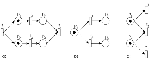
Parallel activities or concurrency (see ) can easily be expressed in terms of a PN. In general, two events are said to be concurrent if they are causally independent, i.e. one transition may fire before or after or in parallel with the other. An important concept in PNs is that of conflict. Two events are in conflict if either one of them can occur, but not both of them simultaneously. This can be represented by the Petri-net structure shown in . A situation where conflict and concurrency are mixed is called a confusion (see ).
The concept of time is not explicitly given in the original definition of Petri nets. However, for the performance evaluation and scheduling problems of dynamic systems it is necessary to introduce time delays. Transitions may be interpreted as actions or as events, like the start of an action or the end of it. In the first case, a delay is associated with a transition, while in the latter case, events are instantaneous and the delay is associated with a token generated by the transition. The size of the delay, however, is determined by the transition that created the token. Time delays may be either deterministic or stochastic. In this work timed Petri nets with deterministic time delays are used to model the behaviour of a production system.
As described in Citation6, there are three basic ways of representing time in Petri nets: firing durations, holding durations and enabling durations. The names given to Petri nets augmented with time vary greatly from one researcher to another. The firing-duration principle says that when a transition becomes enabled it removes the tokens from input places immediately but does not create output tokens until the firing duration has elapsed. In Citation9 a well-defined description of this principle is given. Holding durations work by classifying tokens into two types, available and unavailable. Available tokens can be used to enable a transition, whereas unavailable tokens cannot. To each transition a time duration is assigned, and when firing occurs, the action of removing and creating tokens happens instantaneously. However, the created tokens are not available to enable new transitions until they have been in their output place for the time specified by the transition that created them. This principle is graphically represented in , where available tokens are schematized with the corresponding number of undistinguishable (black) tokens and unavailable by the fact that its center is not filled. When the time duration assigned to the transition is not 0, this value is given beside the transition, e.g. f(t 1) = td . In , t denotes a model time represented by a global clock. With enabling durations the firing of the transitions happens immediately and the time delays are represented by forcing transitions that are enabled to stay so for a specified period of time before they can fire.
Holding durations and firing durations are in fact the same way of representing time. We prefer the use of holding durations, because in comparison to firing durations they do not have transitions that remain active over periods of time. Thus, the interpretation of Petri nets using holding durations is closer to that of non-timed Petri nets.
The main difference between using holding and enabling durations can be seen in a Petri net where conflict or confusion appears. In this case more transitions are enabled by one marking. When enabling duration policy is used, the firing of one transition can interrupt the enabling of other transitions, as the marking, which has enabled previous situation, has changed Citation6. It is natural to use holding durations in modelling most processes as transitions represent events, and generally once an event starts it does not stop to allow another event to occur.
By using holding durations the formal representation of the timed Petri net is extended with the information of time, represented by the tuple
P, T, I, O are the same as above; | |||||
s 0 is the initial state of a timed Petri net; and | |||||
| |||||
The state of a timed Petri net is now a combination of three functions, one of which describes the distribution of available tokens in places, the second the distribution of unavailable tokens, and the third one is the remaining-holding-time function. Note that this interpretation of state is similar to Citation9 but there a firing duration principle is used. Formally, the state of a timed Petri net is a triple s = (m, n, r) where:
m : P → ℕ is a marking function of available tokens. It defines a g×1 column vector m whose ith entry is m(pi ); | |||||
n : P → ℕ is a marking function of unavailable tokens. It defines a g×1 column vector n whose ith entry is n(pi ); and | |||||
r is a remaining-holding-time function that assigns values to a number of local clocks that measure the remaining time for each unavailable token (if any) in a place. This means that if the number of unavailable tokens in a place pi is equal to l, n(pi ) = l, the remaining-holding-time function r(pi ) defines a vector of l positive real numbers denoted by r(pi ) = [r(pi )Citation1, r(pi )Citation2, …, r(pi ) [l]]; r is empty for all those places pi for which n(pi ) = 0. | |||||
A transition tj is enabled by a given marking if, and only if, m(pi ) ≥ I(pi , tj ), ∀ pi ∈ P. The firing of transitions is considered to be instantaneous. Initial values of local clocks are set as prescribed by the transitions that produced the corresponding unavailable tokens. When no more transitions are enabled at the current time, the time of the global clock is incremented by the value of the smallest local clock. A token in a place with this local clock becomes available and the enabling condition is checked again. The procedure for determining a new state is described in detail in section 4.
3 The modelling of production systems
In this section we present the modelling of production systems using timed Petri nets based on data from production management systems. Many classes of Petri nets can be used to describe a production process, like state machines, marked graphs, assembly Petri nets, etc. Van der Aalst Citation5 provides a method for mapping scheduling problems onto timed Petri nets, where the standard Petri-net theory can be used. To support the modelling of scheduling problems, he proposed a method to map tasks, resources and constraints onto a timed Petri net. In this paper a different representation of time in Petri nets is used and the structure of the model is derived from existing production management data. The Petri-net model can be built based on the data stored in production management information systems such as MRP II systems. Here we provide a method for recognizing basic production elements from the management system's database.
The general modelling method can be summarized in the following steps. First, operations and resources should be identified. Next, the relationships between the identified operations have to be determined. From here the initial net structure can be designed. In this step the places and transitions that represent operations are designed and arranged according to the identified relationship. Then we have to designate places that model the statuses of the resources and conditions. Finally, we need to determine the initial number of tokens covering all the places according to the system's initial state and associate the time durations with transitions. Finally, the net model should be checked to see whether it reflects the system operation as defined in the MRP II system, and modified if needed. The Petri-net model can be used to verify and validate the logical properties of the behaviour of the modelled processes. When timed Petri nets are used, it is possible to derive performance measures such as makespan, throughput, production rates, and other temporal quantities. In this work the simulation of a timed Petri net is used to estimate the performance measures and evaluate different priority rules.
3.1 The modelling of production activities
Here we present a method of describing the production system activities with timed Petri nets using the holding-duration representation of time. The places represent resources and jobs/operations, and the transitions represent decisions or rules for resources assignment/release and for starting/ending jobs.
To make a product, a set of operations has to be performed. We can think of an operation as a set of events and activities. Using a timed PN, events are represented by transitions and activity is associated with the presence of a token in a place.
An elementary operation can be described with one place and two transitions, see . When all the input conditions are met (raw material and resources are available) the event that starts the operation occurs, t 1. This transition also determines the processing time of an operation. During that time the created token is unavailable in place p 2 and the operation is being executed. After that time the condition for ending the operation is being satisfied and t 2 can be fired. Place p 1 is not a part of the operation, it determines the input condition, e.g. the availability of the input material.
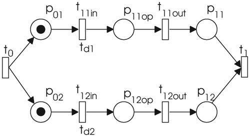
When parallel activities need to be described, the Petri-net structure presented in is used. Transition t 0 sets the input conditions for the parallel execution of two operations. In places p 01 and p 02 the operations can wait for the available resource(s). When all the conditions are satisfied, an operation can begin with the execution. The time delays of the transitions t 11in and t 12in define the duration of each operation. An available token in place p 11out (p 12out) indicates that operation is finished. Transition t 1 is used to synchronize both operations.
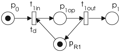
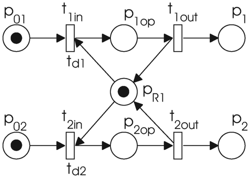
An operation might need resources, usually with a limited capacity, to be executed; this is illustrated in . Place p R1 is used to model a resource. Its capacity is defined with the initial marking of that place. The resource is available to process the operation if there is an available token in it. When the resource is used at the start of the operation the unavailable token appears in place p 1op. After the time defined by transition t 1in the token becomes available, t 1out is fired, and the resource becomes free to operate on the next job. For this reason zero time needs to be assigned to the transition t 1out. An additional place p 1 models the control flow. When the token is present in this place, the next operation can begin.
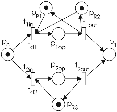
A particular operation can often be done on two different (sets of) resources with different availability, and the time duration can be different on each set of resources. Therefore, this is represented as two operations, which are coupled as shown in . If the operation containing p 1op were to be executed two different resources would be needed. The duration is specified with the transition t 1in. In the case when the operation containing p 2op is chosen, resource p R3 is needed.
There are common situations where more operations use the same resource, e.g. an automated guided vehicle (AGV) in a manufacturing system, a mixing reactor in a batch system. This can be modelled as shown in .
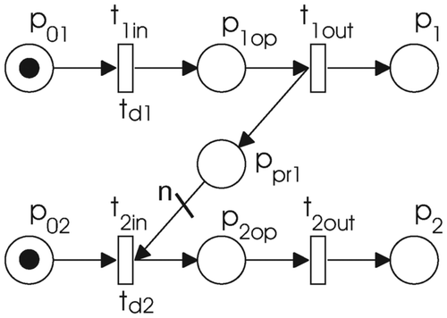
Precedence constraints are modelled by adding an extra place p pr1, which in this way also models the control flow. shows the situation where the task presented with nodes t 1in, p 1op and t 1out precedes the task presented with nodes t 2in, p 2op and t 2out, i.e. the execution of the task that contains p 1op has to be completed before the execution of the task with p 2op can start. The weight n of the arc, which connects p pr1 to t 2in, prescribes how many items need to be produced by the first operation before the second operation can begin.
In Petri-net modelling, the place nodes can be used to represent the status of a resource (e.g. its availability), the stage of a process plant operation (e.g. undergoing) or a condition (e.g. its satisfaction). The presence of a token in a place indicates whether a resource is available, a process plant operation is undergoing, or a condition is true (e.g. material is available). More than one token in a resource place often implies the availability of several resources of the same type. Transition nodes are used to model events, e.g. the starting and ending of an operation.
3.2 Modelling using the data from production management systems
Data stored in production management information systems, such as MRP II systems, can be used to build a Petri-net model. Data about the structure of a production facility and about the products are needed. The product structure is given in the form of the BOM and the process structure in the form of routings. These two groups of data items, together with the given resource units, form the basic elements of the manufacturing process. These data can be effectively used to build up a model of the production system with Petri nets.
The BOM is a listing or description of the raw materials and items that make up a product, along with the required quantity of each.
R = {r 1} is a root item; | |||||
E = {e 1,…, ei } is a finite set of subitems; | |||||
q : E → ℕ is the function that defines the quantities for each subitem ei . q represents an i×1 column vector whose ith entry is q(ei ); and | |||||
pre : (E×E) → {0, 1} is a precedence-constraints function. It defines the precedence-constraints matrix pre, where pre(i, j) = 1 indicates that the ith item precedes the jth item. It can also be interpreted as a directed graph. | |||||
R is a root item, representing the product, that is composed of subitems described with E. The number of required subitems is determined with vector q. When a subitem has to be produced before another, the precedence function pre is used to define it. All the subitems have to be finished before the operation for the subsequent subitems can begin. A required property of pre is that only zero values can be on its diagonal, i.e. a subitem cannot precede itself. It is assumed that cycles in the precedence relation do not occur as this would have no sense in the context of BOM. The absence of cycles can be checked from the corresponding directed graph.
If any of the subitems ei is composed of other subitems, the same definition is used to describe its dependencies. Listings of all the items that appear in a product are defined by the BOM structure of a product.
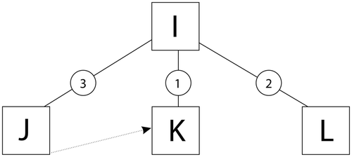
In there is an example of a BOM describing the production of product I. It is composed of three components, i.e. three items of J, one K item and two items of L. From the graph it is clear that all of the items J have to be completed before the production of item K can begin. Its representation in tabular form is presented in . The work order (WO) determines how many of the finished products have to be produced. In this example it is presumed that q 0 of product I has to be produced.
Table 1. Example of the BOM structure.
In our example the BOM of product I would be represented as:
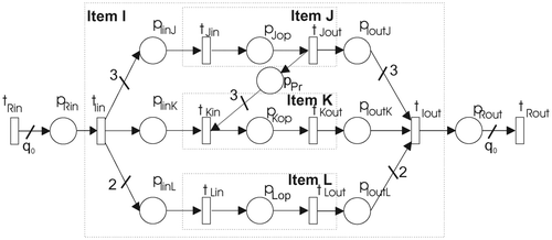
To start with, let us assume that for each item from the BOM only one operation is needed. Hence, an item is represented with an operation. To be able to prescribe how many of each item is required the transition t Rin and the place p Rin are added in front, and p Rout and t Rout are added behind this operation. The weight of the arcs that connect t Rin with p Rin and p Rout with t Rout are determined by the quantity q 0 of the required items. In this way an item I is represented with a Petri net defined as:
The structure of one item is represented graphically in .
The finished product is defined with a structure of BOMs. In this way the construction of the overall Petri net is an iterative procedure that starts with the root of the BOM and continues until all the items have been considered. If the item requires any more subassemblies (i.e. items from a lower level) the operation, the framed area of the PN structure presented in , is substituted with lower-level items. If there are more than one subitems, they are given as parallel activities.
The substitution of an item with subitems is defined as follows:
-
Remove the place p Xop and its input/output arcs.
-
Define the PN structure for subcomponents, as it is defined with a BOM: function PN1 = placePN(R, E, q, pre). Consider the precedence constraints.
-
Replace the removed place p Xop by the subnet defined in the previous step. The input and output transitions are merged with the existing ones: PN = insertPN(PN, PN1). Structure PN1 is inserted to the main structure PN.
In the PN structure of the example from is given, where item I is composed of three subitems: J, K and L. With function placePN() also precedence constraint is added, which defines that all three items J have to be finished before the production of item K can begin.
For each item that can appear in the production process, and does not represent a raw material, a routing is defined. It defines a sequence of operations, each requiring processing by a particular machine for a certain processing time. The routing information is usually defined by a routing table. The table contains a header, where the item that is being composed is defined and the lines where all the required operations are described. For each operation one line is used.
Each operation that appears in the routing is placed in the model using function constructPN(). If the operation can be done with alternative resources the Petri-net structure presented in is used. If two operations can be done concurrently the Petri-net structure from is used. The time durations of the operations are assigned to the transitions. All the placed operations are connected as prescribed by the required technological sequence. The required resources are assigned to the operations. The resource is represented by a place, where its capacity is demonstrated by the initial number of tokens in it.
The implementation of the routing data in one component of a BOM is defined as follows:
-
Remove the place p Xop and its input/output arcs.
-
Define a PN structure for the subcomponents, as it is defined with routing data: function PN1 = constructPN(PN, datRoute).
-
Replace the removed place p Xop by the subnet defined in the previous step. The input and output transitions are merged with the existing ones: PN = insertPN(PN, PN1). Structure PN1 is inserted to the main structure PN.
A routing for item K is presented in . Three operations are needed to produce this item; the first of these operations can be done on two different resources. Similar notation can be used for other possible cases, e.g. an operation that needs three resources R 1 and two R 2, or one resource R 1 and three R 3 would be presented by 3R 1, 2R 2 (R 1, 3R 3). Round parentheses are used here to distinguish different sets of resources, where one set of them would be used to perform an operation. Within the routing table concurrent operations are considered as a single operation with a parallel internal structure, as shown in .
Table 2. Routing of product K.
The PN structure in is achieved if the sequence of operations described with a previous routing is modelled. The resulting PN structure is inserted into the main PN model, using function insertPN().
The routings are submodels that are inserted (by substitution, as defined previously) into the main model defined with the BOM. However, these subitems can also be described with a BOM, i.e. in the case they are composed of semi-products. The construction of the overall Petri-net model can be achieved by combining all of the intermediate steps.
The products to be produced and the required quantities of the finished products are determined by a WO. A Petri-net model is built for each product as defined with the BOM and routing data. At the end the Petri-net model should be verified against the given data and simplified, if possible, i.e. redundant nodes, if any exist, should be eliminated. A node is considered redundant when it can be removed without affecting the simulated behaviour of the model. An example of such a simplification is given later in .
The modelling procedure can be summarized in the following algorithm:
-
Algorithm 1
-
[R, q] = readWO()
-
For i = 1 to length(R)
-
PN = placePN(R(i), [ ], q(i), [ ])
-
PN = routing(PN, R(i))
-
end
-
First, data about the WO are read. The products that are needed to be produced are given in R, and in vector q the quantities of the desired products are passed. For each product, first the Petri-net structure PNEi is determined and placed on the model. The weight qi is assigned to the corresponding arcs. Precedence constraints are added if they exist. The step when the routing() is called is described in more detail with algorithm 2:
-
Algorithm 2
-
function PN = routing(PN, R)
-
datRoute = readRouting(R)
-
[E, q, pre] = readBOM(R)
-
for i = 1 to length(datRoute.Op)
-
if datRoute.Resources == BOM
-
PN1 = placePN(R, E, q, pre)
-
for j = 1 to length(E)
-
PN1 = routing(PN1, E(j))
-
PN = insertPN(PN, PN1)
-
end
-
else
-
PN = constructPN(PN, datRoute(i))
-
end
-
end
-
First, the routing and the BOM data are read from the database. For each operation that comprises the routing, the algorithm checks if it is made up of subitem(s). If this is the case, function placePN() is used to determine the PN structure of the given structure BOM. For each of those subitems the routing data need to be implemented. With function insertPN() the resulting subnet is inserted into the main PN structure. If the operation represents the production operation, function constructPN() is called. Basic elements ( – ) are recognized and placed in the model, again using function insertPN(). All the data about resources and time durations are acquired from the routing table. The described algorithm has been implemented in Matlab®.
4 Simulator – scheduler
A Petri-net model can be used to verify and validate the logical properties of the behaviour of modelled processes. The analysis can be based either on the reachability (coverability) tree or the calculation of the invariants. For complex models such an analysis is computationally expensive. Instead, certain properties can be estimated by simulation. Using a simulation the evolution of the marking through time can be observed. Different heuristic rules can be introduced when solving the situations when conflicts occur. In this way different evolutions of the Petri net are usually possible. When the marking of the places that represent resources is being considered, the schedule of process operations can be observed, i.e. when, and using which resource, a job has to be processed. Usually, different rules are needed to improve different predefined production objectives (makespan, throughput, production rates, and other temporal quantities).
To show the practical applicability of the proposed modelling method for the purposes of scheduling we built a simulator in Matlab® that takes a Petri-net model generated by the above algorithm. The simulator allows different priority dispatching rules to be implemented. With the simulation, a marking trace of a timed Petri net can be achieved. The marking trace of places that represent resources is characterized as a schedule. The simulator is able to deal with situations when a conflict occurs, the conflict being solved by a decision maker. By introducing different heuristic dispatching rules (priority rules) decisions can be made easily. In this way, only one path from the reachability graph is calculated, which means that the algorithm does not require a lot of computational effort. Depending on the given scheduling problem a convenient rule should be chosen.
The procedure of each simulation step computes a new state s k+1 = (m k+1, n k+1, r k+1) of a timed Petri net in the next calculation interval:
-
Get the marking of the classical (untimed) Petri net, i.e. only available tokens are considered. Calculate the corresponding firing vector uk of the untimed Petri net. At this point a conflict resolution is also applied.
m k → u k.
-
If no transition is being fired (uk = 0), the time passes on – the values of the local clocks are decreased by the value of the smallest local clock.
M k = m k + n k ,
Ts = min p i ∈ P (min l (r k (pi )[l])), r(pi ) is not empty,
r k+1(pi ) = r k (pi ) − Ts , ∀r(pi )[l], ∀pi ∈ P and r(pi ) is not empty – remove functions for tokens that became zero,
n k+1(pi ) = dim(r k+1(pi )), ∀pi ∈ P and r(pi ) is not empty,
m k+1 = M k − n k+1.
-
In other cases (u k ≠ 0), the time remains the same. The firing vector uk defines the new state of the timed Petri net, i.e. the distribution of tokens over the places and the values of local clocks corresponding to newly created tokens.
M k = m k + n k ,
M k+1 = M k + (O − I) · uk ,
n k+1(pi ) = nk (pi ) + O(pi , tj ) · ukj , ∀pi ∈ P and ∀tj ∈ {t ∈ T : f(t) > 0},
r k+1(pi ) = r k (pi ); r k+1(pi )[h] = f(tj ), for h = lik + 1, … , l i k+1 , where l i k+1 = lik + O(pi , tj ) · ukj , ∀pi ∈ P and ∀tj ∈ {t ∈ T: f(t) > 0},
m k+1 = M k+1 − n k+1.
The simulation is finished when there are no unavailable tokens in a model or the global clock reaches the predefined stop time.
In this algorithm the firing of the transitions is instantaneous. This is solved by the fact that time is not passed on when any transition is enabled. It is assumed that the situations where the enabling (firing) of a transition at one time instant is cycling are prohibited. By cycling we mean a repetitive sequence of consecutively enabled transitions with zero-time delay. Such a cycle would stop the progress of the simulation. This kind of situation would only occur in the case of incorrect modelling.
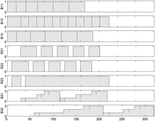
After the simulation is finished the marking over the time can be observed. A Gantt chart can be produced if the evolution of the marking in the places that represent the resources is observed. From it, the schedule of the modelled process can be obtained.
5 A case study: Multiproduct batch plant
The applicability of our approach will be demonstrated on the model of a multiproduct batch plant designed and built at the Process Control Laboratory of the University of Dortmund. The demonstration plant is relatively simple compared to industrial-scale plants, but poses complex control tasks. A detailed description of the plant can be found in Citation24.
In the following a brief description of the plant will be given. From the data given in production management systems a timed Petri-net model is built. With the help of a simulator/scheduler using different scheduling rules, different schedules can be achieved. At the end the results for the given problem are presented and compared with the results achieved with other techniques.
5.1 Description of the plant
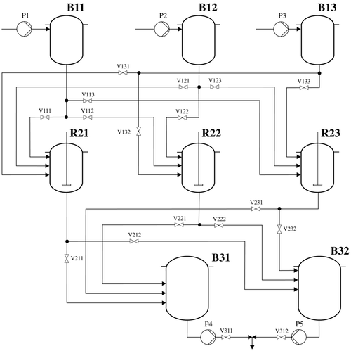
The process under consideration is a batch process that produces two liquid substances, one blue, one green, from three liquid raw materials. The first is coloured yellow, the second red and the third is colourless. The colourless sodium hydroxide (NaOH) will be referred to below as white. The chemical reaction behind the change of colours is the neutralization of dilute hydrochloric acid (HCl) with dilute NaOH. The dilute HCl acid is mixed with two different pH indicators to make the acid look yellow if it is mixed with the first one and red when mixed with the second one. During the neutralization reaction the pH indicators change their colour when the pH value reaches approximately 7. The first indicator changes from yellow to blue, and the second from red to green.
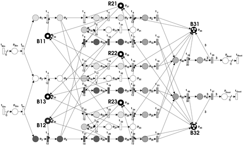
The plant consists of three different layers, see . The first layer consists of the buffering tanks B11, B12 and B13, which are used for holding the raw materials ‘Yellow’, ‘Red’ and ‘White’. The middle layer consists of three stirred tank reactors, R21, R22 and R23. Each reactor can be filled from any raw-material buffer tank. The production involves filling the reactor with one batch of ‘Yellow’ or ‘Red’ and then neutralizing it with one batch of ‘White’. The lower layer consists of two buffer tanks, B31 and B32, in which the products are collected from the middle layer. Each of them is used exclusively for ‘Blue’ or ‘Green’ and can contain three batches of product. The processing times of the plant are presented in . The system can be influenced through different inputs, pumps P1 – P5 and valves V111 – V311.
Table 3. Processing times.
5.2 The scheduling problem
The plant provides a variety of scheduling problems. The following example deals with a problem as follows:
a set of production resources and corresponding capacities; | |||||
a set of products that can be produced, with associated constraints, production parameters, routings and the BOM; and | |||||
a set of demands – an order for a specific amount of finished products. In this case six batches of ‘Blue’ and six batches of ‘Green’ products are required. | |||||
a feasible schedule that ensures that enough material at each BOM level is produced to satisfy the demands, i.e. time instances when the raw material must be available. The schedule needs to respect all production constraints and resource availabilities. From the schedule the duration of the whole procedure is determined; and | |||||
easy visualization of the production schedule. | |||||
5.3 Structure of the production facility given in production management systems
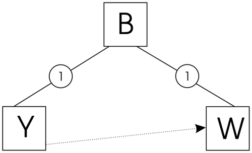
The BOM (equivalent to Formula), which defines the structure of the finished product, i.e. the production of one ‘Blue’ batch requires one ‘Yellow’ and one ‘White’ batch, is shown in and . A precedence constraint exists, which defines that the ‘Yellow’ has to be poured into the reactor before the ‘White’ batch. The structure of the ‘Green’ product is given in a similar way.
Table 4. BOM for the finished product ‘Blue’.
The routing that specifies the operations to produce item B is given in . The operation Op10 just introduces the place for subitems defined with a BOM.
Table 5. Routing of product ‘Blue’– set of operations.
Work orders define how many finished products are needed. From this the requirements for raw materials are determined. For our case this means that six batches of ‘Yellow’ and ‘Red’ and twelve batches of ‘White’ are needed.
5.4 Modelling
Data from the BOM and the routings were used to build a Petri-net model. The finished product ‘Blue’ is defined with the BOM given in and .
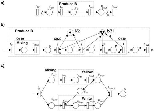
When we apply the first step of our algorithm, the PN structure PNEi , shown in , is obtained. The elements t Bin, pB and t Bout represent the operation of this root item, i.e. the production of a ‘Blue’ batch.
In the second step, when routing data for this root item ( ) were used, a more exact model is achieved. The structure is shown in . For a clear representation only one mixing reactor is assigned to Op20 and Op30. The mixing operation requires two raw materials, which are recognized from a BOM, i.e. two subitems.
The same algorithm is used again to describe Op10 in more detail. Two additional PN structures, PNEi , are added to the model. One represents the operation of ‘Yellow’ batch production and the other one the production of the ‘Blue’ batch. From the data given ( , ) the dependency of these two operations can be recognized, and this results in an additional place, p pr. In this way the submodel of mixing is achieved, as shown in .
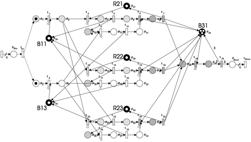
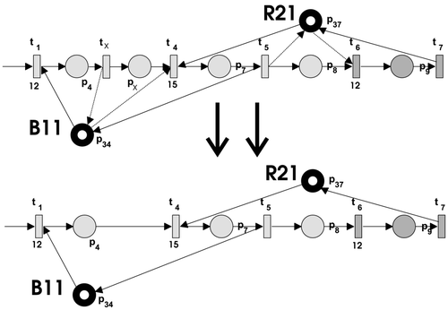
After the whole procedure is finished, a detailed timed Petri-net model of the production of the ‘Blue’ batch is obtained. Its structure is represented in . Some simplifications were made at the end with the intention of removing redundant places, transitions and arcs. The general rule for the simplification of Petri-net models is still a subject of further work. For example, if two successive operations use the same resource, like the operations modelled with t 1, p 4 and t 4, p 7, the connecting place that would model the control flow is not needed. This simplification is illustrated in . Places are filled with different grey casts to represent different operations that they model. The black fill is used to mark the places that model the availability of the resources.
The same procedure was performed to model the production of ‘Green’ product, and the Petri-net model given in represents the given scheduling problem.
5.5 Results
The scheduling problem was mapped onto timed Petri nets, and the batch process was modelled with timed Petri nets. The simulator/scheduler was used to schedule the tasks that are needed to produce the desired amount of finished products. We tested different priority rules (SPT, LPT), introduced in section 1, and with them different schedules were achieved. The literature, for example Citation3,Citation19, contains many proofs that SPT schedules are the best for a number of objectives, including flowtime. The schedule allows an easy visualization of the process and ensures that enough raw materials (‘Yellow’, ‘Red’ and ‘White’ batches) are available at the right time. It respects all the production constraints and the duration of the whole process can be identified from it. The shortest duration, i.e. 315 s, would be achieved if the batches were scheduled as determined with the SPT priority rule. The Gantt chart of this schedule is presented in . The Gantt chart presents the usage of the resources (ordinate) over the time (abscissa).
The results were compared with the results achieved using the algorithms presented in Citation24 and Citation1, see . Using the first algorithm the whole procedure would be finished in 323 s, and in the latter case, 329 s. This implies that the scheduling algorithm used in this work is more effective, even though calculating the schedule only takes a short time.
Table 6. Results.
6 Conclusion
Timed Petri nets with the holding-duration principle of time implementation were used to model basic production activities. A procedure for using existing data from production management systems to build the Petri-net model was developed. For the particular timed Petri net we present a simulator that can be used to simulate models built with timed Petri nets. For the purposes of scheduling, different heuristic rules can be introduced to the simulator. The applicability of the proposed approach was illustrated on a practical scheduling problem, where the data about the production facility is given with the BOM and routings. The model achieved with the proposed method was used to determine a schedule for production operations.
The proposed method is an effective way to get an adequate model of the production process, which can be used to develop different analyses of the treated system, e.g. schedules.
References
- Gradišar , D. and Mušič , G. 2004 . Scheduling production activities using project planning tool . Electrotechnical Review , 71 : 83 – 88 .
- Panwalkar , S. S. and Iskaneder , W. 1977 . A survey of scheduling rules . Operations Research , 25 : 45 – 61 .
- Blackstone , J. H. , Phillips , D. T. and Hogg , G. L. 1982 . A state-of-the-art survey of dispatching rules for manufacturing job shop operations . International Journal of Production Research , 20 : 27 – 45 .
- Murata , T. 1989 . Petri nets: properties, analysis and applications . Proceedings of the IEEE , 77 : 541 – 580 .
- Van der Aalst , W. M.P. 1996 . “ Petri net based scheduling ” . In OR Spectrum 219 – 229 .
- Bowden , F. D.J. 2000 . A brief survey and synthesis of the roles of time in petri nets . Mathematical & Computer Modelling , 31 : 55 – 68 .
- Freedman , P. 1991 . Time, petri nets, and robotics . IEEE Transactions on Robotics and Automation , 7 : 417 – 433 .
- Zuberek , W. M. and Kubiak , W. 1999 . Timed petri nets in modeling and analysis of simple schedules for manufacturing cells . Computers and Mathematics with Applications , 37 : 191 – 206 .
- Zuberek , W. 1991 . Timed petri nets: definitions, properties and applications . Microelectronics and Reliability , 31 : 627 – 644 .
- López-Mellado , E. 2002 . Analysis of discrete event systems by simulation of timed petri net models . Mathematics and Computers in Simulation , 61 : 53 – 59 .
- Gu , T. and Bahri , P. A. 2002 . A survey of petri net applications in batch processes . Computers in Industry , 47 : 99 – 111 .
- Van der Aalst , W. M.P. 1998 . The application of petri nets to workflow management . Journal of Circuits Systems and Computers , 8 : 21 – 66 .
- Zhou , M. C. and Venkatesh , K. 1999 . Modelling, Simulation, and Control of Flexible Manufacturing Systems: A Petri Net Approach , Singapore : World Scientific .
- Recalde , L. , Silva , M. , Ezpeleta , J. and Teruel , E. 2004 . “ Petri nets and manufacturing systems: an examples-driven tour ” . In Lectures on Concurrency and Petri Nets , Vol. 3098 , 742 – 788 . Berlin : Springer-Verlag .
- Yu , H. , Reyes , A. , Cang , S. and Lloyd , S. 2003 . Combined petri net modelling and AI based heuristic hybrid search for flexible manufacturing systems – Part 1. Petri net modelling and heuristic search . Computers & Industrial Engineering , 44 : 527 – 543 .
- Tacconi , D. A. 1997 . A new matrix model for discrete event systems: application to simulation . Control Systems Magazine, IEEE , 17 : 62 – 71 .
- Matcovschi , M. H. , Mahuela , C. and Pastravanu , O. Petri net toolbox for MATLAB . 11th IEEE Mediterranean Conference on Control and Automation MED'03 . Greece.
- Ratzer , A. , Wells , L. , Lassen , H. , Laursen , M. , Qvortrup , J. , Stissing , M. , Westergaard , M. , Christensen , S. and Jensen , K. CPN tools for editing, simulating, and analysing coloured petri nets . Proceedings of the 24th ICATPN 2003 . Netherlands. pp. 450 – 462 .
- Zhou , M. C. , Chiu , H. and Xiong , H. H. Petri net scheduling of FMS using branch and bound method . Proc. 1995 IEEE Int. Conf. on Industrial Electronics, Control and Instrumentation . pp. 211 – 216 .
- Julia , S. and Valette , R. 2000 . Real time scheduling of batch systems . Simulation Practice and Theory , 8 : 307 – 319 .
- Berning , G. , Brandenburg , M. , Gürsoy , K. , Kussi , J. S. , Mehta , V. and Tölle , F. 2003 . Integrating collaborative planning and supply chain optimization for the chemical process industry (I) – methodology . Computers and Chemical Engineering , 28 : 913 – 927 .
- Czerwinksi , C. S. and Luh , P. B. 1994 . Scheduling products with bills of materials using an improved lagrangian relaxation technique . IEEE Transactions on Robotics and Automation , 10 : 99 – 111 .
- Yeh , C. H. 1997 . Schedule based production . International Journal of Production Economics , 51 : 235 – 242 .
- Potočnik , B. , Bemporad , A. , Torrisi , F. D. and Mušič , G. 2004 . Zupančič, B.: Hybrid modelling and optimal control of a multiproduct batch plant . Control Engineering Practice , 12 : 1127 – 1137 .
