Abstract
The modelling via transmission elements, which was originally introduced to model the kinematics and dynamics of multi-body systems, is applied to modelling electric drive systems with switch circuits in this article. This approach is implemented in C++ in the simulation software Drive&Control D&C Engine which is designed to model and simulate mechatronic systems in the drive engineering by the department of advanced engineering of the Bosch Rexroth AG.
The switch elements, used in the power converters of electric drive systems, are treated as ideal switches and are described in an efficient, stable way. Discontinuities caused by the ideal switch models are dealt with an event-handling algorithm. The application example is a complete permanent-magnet-synchronous-motor (PMSM) drive system. A benchmark simulation is carried out to demonstrate this approach's performance in terms of computational time and accuracy.
1. Introduction
Modern hydromechanical or electromechanical drive systems are composed of components from different physical domains. Using the signal-oriented approach to model such systems usually results in a huge amount of effort to derive the explicit form of the equations. Beyond this drawback, models of the signal-oriented approach lack hierarchical structures, and are hardly reusable. The object-oriented modelling of physical systems, first introduced by Elmqvist [Citation1], can be used to overcome such difficulties. In recent years, this paradigm has become the mainstream in the physical modelling. After a series of international efforts, the ModelicaFootnote 1 language was developed in 1999 to support the physical modelling. Since then it has become more and more significant in the industrial application. At the moment several commercial simulation programmes of mechatronic systems support its syntax and semantics, for example, Dymola [Citation1].
The efficiency of the physical modelling paradigm, especially the acausal modelling with the Modelica language, depends strongly on its language compiler and preprocess optimization, where all of the declarative equations of the models are sorted and computed symbolically. Concerning the aspect of conservation laws at nodes, for example, power continuity and mass balance, the modelling via transmission elements does have the similar root as that of the physical modelling paradigm. The largest difference is that it offers another approach to generalize the equations of multi-domain systems in a numerical manner. Due to the implementation in C++, the declarative structure of models and acausal approach are not supported. This approach was primarily used for modelling the kinematics and dynamics of multi-body systems in Refs. [Citation2] and [Citation3]. Its applications in hydraulic systems can be found in Ref. [Citation4]. In this article, the approach is applied to model electric systems, and has been implemented in the simulation software named D&C Engine.
Switching power converters are frequently applied to control the electric motors in modern electric drive systems. Simulation of such converters is problematic for several reasons. They are operated by the frequent switching up to several hundred kHz. In contrast, the time constants of mechanical parts are of larger magnitude than the switching period. This property makes the equation system potentially stiff. On the other hand, each switching event, in an ideal sense, is a discontinuity. Typical power converter simulations can run for hundreds or thousands switching cycles, which may lead to numerical problems for simulation software that does not have an explicit mechanism for handling these discontinuities. Problems are, for example, long simulation time, lack of convergence and convergence to an erroneous solution.
As default solution of many simulation tools, the switch is non-ideally modelled by a variable resistor, in which the resistance is assumed to be a small value at switch-on and a large value at switch-off. This may introduce an artificial stiffness to equation systems and may lead to inaccurate results [Citation5]. In most cases of simulating complex electric drive systems, the dynamics of circuits during switching is of little interest. Hence, the switch operation can be regarded as instantaneous and the switch itself can be treated as ideal and controlled by discrete states, such as the variables of the enumeration type ON and OFF.
The ideal switch model, in the object-oriented fashion, involves however the change of the modelling causality and leads to variable structure systems in simulation. To deal with these problems, modelling ideal switches by using parameterized curves has been developed for the physical modelling paradigm, for example, in Ref. [Citation6]. In some cases the model with ideal elements can still change its structure during the simulation, so very small resistance and conductance are used in the standard electrical library of Modelica to tackle this problem [Citation5]. The ideal switch model has been described by using constraint equations, implemented as transmission elements in Ref. [Citation7]. This method, however, due to the implicit nature of differential algebraic equations (DAE), could be superior in terms of the computational performance only in case of extremely stiff systems. The ideal switch has been handled by using a linear complementary formulation [Citation8]. But it seems to be difficult to apply this approach in an object-oriented modelling environment and be applicable only in special cases (e.g. it seems to be impossible to describe an ideal thyristor) [Citation6]. The above-mentioned disadvantages have been overcome by implementing the complete ideal power converter as one whole transmission element. Inductive elements that couple directly with power converters are considered in the model.
Discontinuities, which are caused by the ideal switch models, are dealt by an event-handling algorithm integrated in the D&C Engine. They are described as events, which can be divided into two types: time and state events. Time events can be directly provided in form of a linearly linked list of time points for the integration algorithm, which is able to hit the point accurately with its step-size control. The basic idea of handling the state events is to lock the system equations in the subintervals [Citation9]. Event conditions are specified in the form of a set of root functions. An event occurs if a value of the root functions crosses through zero. The root-searching algorithm locates its exact time occurrence, and the integration process will be stopped. After the proper handling it will be restarted. The implementation in the D&C Engine was demonstrated in Ref. [Citation7].
Due to the fact that the time constants of power converters are much smaller than those of mechanical parts, the equation systems of electric drive systems are potentially stiff. For this reason, the implicit integration algorithm RADAU5 [Citation10] is applied for the simulation experiments. The application example is a permanent-magnet-synchronous-motor (PMSM) drive system. Its model is set up in the D&C Engine and a commercial simulation tool, respectively. The performance in terms of computational time and accuracy is demonstrated by means of a benchmark simulation.
2. Modelling via transmission elements
The basis for the following modelling is the classification of its components into two categories: state objects and transmission elements. Transmission elements are models of physical or signal components, whose composition yields the equation system that can be solved by an equation solver. State objects hold the information about this equation system in the form of state variables, their derivatives, algebraic variables and their residuals. They serve as the interface between the mathematical models and equation solvers.
2.1. Transmission elements
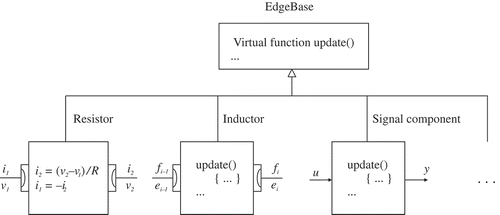
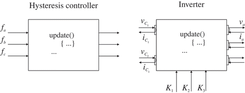
The behaviour of physical components can be considered as transmission function regardless of currents, forces, flow rates and so on. This common property can be defined as virtual function of an abstract object, whose implementation can be easily performed by using the abstraction mechanisms of the object-programming language such as C++. The abstract object, in our case, is defined as a basic class called EdgeBase, see . It owns the virtual member function named Update for the description of transmission behaviours. The transmission elements on the level of physical objects are the classes derived from the basic class EdgeBase. A concrete example of electrical resistors is shown for the Update function in . The virtual function Update of its base class can be locally overridden by those of transmission elements. In this way, the user can restrict himself just to encapsulating the required knowledge, for whatever the physical object contains, into the corresponding transmission element. The C++ compiler ensures that the right function in the right object is invoked in each case. This property also makes the application of the modelling via transmission elements domain-independent. Within one domain, the multi-level inheritance is possible, if a group of components share the same features.
In general there are two types of transmission behaviours to be found. In case of the across–through transmission, the through variable f can be determined by the across variables, while, for the across-across transmission the across variable ei is calculated by the other across variable ei– 1 together with the through variable f. These behaviours refer to voltage-drop-causers and current-flow-causers of electric resistors in Bond Graph. Sensors are special types of transmission elements. An across sensor belongs to the across–through transmission, whose connected across variable is accessed and converted into signal output. No through transmission does occur in it. The through variable of through sensors can be either achieved by means of constraint equations or by using the across–across transmission. In the first case, the difference of across variables over the sensor is forced to be zero with the algebraic variable, namely the through variable; in the second case, the characteristic variables of one side are assigned to the other side, and at the same time the through variable is written as signal output.
Whereas the physical transmission behaviours exhibit the bi-directional nature, the signal-oriented components used in control engineering can be considered as unidirectional transmission elements with the input–output behaviour. It can be treated by any of the two transmission behaviours. Note that, graphically the directed line indicates the connection of signal components and their input–output behaviour, whereas the undirected line denotes the connection of physical components.
The physical transmission elements have interfaces or connectors with respect to the specific domain. They are implemented as classes, and obtain all quantities needed to describe the interaction. Current and voltage are, for example, needed for electrical components. Position, velocity, mass and force are needed for 1D translational mechanics. By using the connectors, the modeller is able to interconnect the component models in a topological way. Just as in reality, connectors of different types cannot be connected with each other. The interactions of different domains are carried out by energy converters, such as electrical motor/generator or hydraulic motor/pump.
2.2. State objects
Beyond the form of generating equations, a set of ordinary differential equations,
Nodes are very useful for generalization of networking. Node objects of physical systems derive from the state object are used to interconnect transmission elements. It offers a unique across variable e, which can be referenced by all interfaces of the connected transmission elements. The sum of all connected through variables is calculated in the node object. To ensure the conservation law, the sum of through variables at the node should be equal to zero according to physical principles. Therefore, it is guaranteed that no transmission elements will ever generate or lose energy in an uncontrolled fashion. This property corresponds domain-dependently the well-known Kirchhoff's current law, Newton's actio et reactio, mass balance in hydraulics and so on. It is subsequently used to determine the right-hand sides of differential equations or the residuals of constraint equations, respectively. An unlimited number of interfaces of transmission elements can be attached to the node object.
2.3. Setup of system equations
The physical modelling paradigm, particularly its recent development, is characterized by the acausal equation-oriented description of models of complex systems. Following this properties strictly, all equations of the models are first acausally stored in a flat model. Global reordering of equations (causalization of equations) and symbolic calculation are inevitable, if they are going to be simulated in an efficient way. This process makes the simulation performance particularly dependent on the stable and powerful Modelica language compiler and its optimizer, which are, at least right now, not as easy to be accessible as a C++ one.
Because of the implementation of C++, the acausal description of a model is impossible by using the approach of transmission elements. However, this guarantees solvable equation systems. Furthermore, it is easier to debug, because the equations refer to the concrete objects. Its models of complex systems consist of a set of state objects and transmission elements. They are assembled in a numbered manner according to their topological structures, which can be obtained by using the well-established graph theory. During simulation the objects are invoked in the same order as they are assembled. The equations of the invoked objects, most of which are assignments in the Update function, are calculated locally. Only equations, given by the dynamics of nodes and transfer behaviour of transmission elements, are abstracted and formulated as a set of semi-explicit DAEs
2.4. Example of an electrical circuit
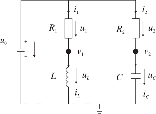
The simple electrical circuit in is used to illustrate the procedure of equation generalizations via transmission elements. This procedure is usually performed by the graphical analysis, but it is illustrated here manually in the purpose of demonstration. Each basic electrical component consists of pins (connectors). They contain current and potential, the physical modelling paradigm alike.
The object equations of basic electrical components, which are encoded in the Update functions of objects, are shown in . Notice that the second equation of the capacitor and the first equation of the node are residual equations. The others, except of the differential equations, are assignments. All components in this circuit are first described by the across–through transmission. That means, the components get the potentials from the pins and provide the currents to them.
Table 1. Equations of basic electrical components
The voltage source and ground provide simply the constant potential references, thus their connection is actually redundant. Their assignment equations will be executed only once at simulation start due to computational efficiency. The connections between the potential-providers and the other components do not yield the equations as the node object does, because the potential variables are already known. The components (R 1, L, R 2 and C) and their connections (the potentials v 1 and v 2) are instantiated in a consecutive way and pushed back into an object vector: first voltage source, second R 1, following L, then node for v 2 between R 1 and L, R 2, C and node for v 2 between R 2 and C. These objects as well as their Update functions are invoked in the same order as the instantiation during simulation. Following this executive scheme, the following set of differential and algebraic equations can be determinated with respect to the derivatives and residuals:
These equations are similar to the results from the nodal approach in the circuit analysis. Note that the procedure of the equation generalization described above, due to the additional algebraic equations, may be computationally inefficient. But its simplicity and easy adaption to other physical domains make it particularly well suited for the modelling of mechatronic systems. More efficient procedure can be achieved by reducing the DAE into an ODE. This, for some circuits, can be achieved by combining different types of transmission behaviours. The technique is demonstrated with the same circuit example as shown in .
The causality of capacitors and inductors, or their types of transmission behaviour, is usually fixed, because in simulation the numerical integration is more preferable than the numerical differentiation. So the across–through capacitor can be expressed as the across–across one, and its object equations are
Replacing the across–through capacitor in , the node equation for the potential v 2 between C and R 2 becomes redundant, because the potential v 2 can be calculated by the assignment with the state variable u.
Similarly the across–across resistor can be described as
By using proper combinations of different transmission behaviours, the DAEs resulting from the electrical circuits may be transformed into the ODE form. But this might be difficult for overdetermined systems, such as circuits with parallel connected capacitors or series connected inductors. In these cases a symbolic processing of the equations is advantageous.
3. Modelling a PMSM drive system
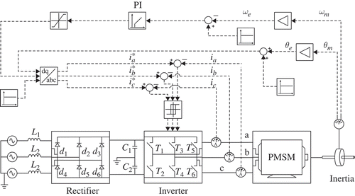
The application example is a PMSM speed servo drive system, which is composed of the machine, speed and position feedback, speed and current controller, smoothing capacitors, alternating current (AC) power supply, inverter and rectifier (see ). The rectifier converts the AC supply into the direct current (DC), where the inductances of the electric net are considered. The DC supply is smoothed by the capacitors. The speed feedback control is used to generate the reference d, q axis currents. Together with the position feedback, these go through the inverse Park transform to provide the a, b, c reference currents. The actual currents are measured by the current sensors. Their values are compared to the references and the error signals are generated. According to these error signals, the hysteresis or pulse-width modulated (PWM) controller fires commands to the six switches of the inverter. The actual motor currents are forced through the frequent on and off switches to equal the commanded values at all times.
The model of this complex electric drive system is completely built up by modelling the components as nodes and transmission elements. The simulation is performed in the D&C Engine. The solid lines illustrated in indicate the physical transmission behaviour of electromechanical parts, whereas the directed dashed lines suggest the signal-oriented transmissions of control parts.
3.1. Machine model
The PMSM has numerous advantages over other machines which are conventionally used as AC servo drives. It is characterized by the higher torque-to-inertia ratio and power density. These properties make it preferable for certain high-performance applications like robotics, aerospace actuators and machine tools. The mathematical model of a PMSM is similar to the well-established d, q model of the wound-rotor synchronous machine. The following assumptions are made for the model applied here.
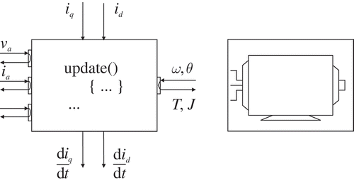
The detailed mathematical derivation, used in this article, can be found in Ref. [Citation11]. As shown in , the transmission element of the PMSM contains three pins (a, b, c) of the three-phase current supply and a rotational mechanical connector for the mechanical shaft. The transmitted variables of the rotational mechanical connector include the angular velocity, angle, momentum of inertia and torque.
For dynamic simulation, the d, q axis equations of the PMSM are expressed in EquationEquations (17)(17) and (18):
The motor torque is
P is the number of pole pairs.
The variables of d, q voltages are obtained from the a, b, c variables through the Clark–Park transform defined below
The variables of a, b, c currents are obtained from the d, q variables through the inverse of the Clark–Park transform defined below
The PMSM model serves as a domain transformer, through which the electrical power is converted into the mechanical power.
The motor dynamics of the mechanical parts is separately described by the node object of 1D rotational mechanics with the following equations
Ji
is the concentrated parameter of the moment of inertia, transmitted by the ith connected transmission element, for example, that of the PMSM. Note that the difference of the synchronous and mechanical speed is , the same for the angle
. This node object can be connected to any 1D rotational transmission elements, for example, other mechanical models or subsystems describing the load side of the like, the damping, friction and gears, can also be considered.
3.2. Current controllers and inverter
For high-performance servo drives, hysteresis or PWM current controllers are used to ensure that the actual currents flowing into the motor are as close as possible to the sinusoidal references. In this application example the hysteresis current controller is used. It is implemented as a signal-oriented transmission element (see ). The control strategy is introduced as follows.
The actual values of ia
, ib
and ic
that are flowing into the PMSM are measured and converted into signals. These values are compared with the sinusoidal reference values of currents ,
and
that are generated by the speed control. Error current signals, for example,
, are subsequently generated. The hysteresis parameter Δi defines the hysteresis bands between
and
. The hysteresis property allows the actual values to exceed or be less than the reference values by Δi, but always within the band. The phase currents are, therefore, approximately sinusoidal as the reference values
are.
Concerning only the stator phase a, the hysteresis property is formulated as root functions , whose sign is continuously observed during simulation. A sign change triggers an event that the hysteresis band is exceeded. The exact occurrence of this event is located by a zero-search algorithm like bisection, after that the proper command will be sent to the commuting switch of the inverter. The switching of the commuting switch (T
1 and T
2) is assumed to occur simultaneously, this means, if the switch gets the control signal OFF and T
1 becomes open, T
2 is at the same time switched on (ON). Note that, the freewheeling diode across its switch are usually applied to make sure that the current through the motor winding does not go to zero instantaneously, if one switch becomes blocked. Due to the complementary properties of commuting switches, this function can be performed by using the commuting switches. The logic of one pulse is shown in . The similar logic can be applied to the other two phases.
Table 2. Logic of the hysteresis controller and the ideal commuting switch for one pulse
The inverter that converts the DC supply into the sinusoidal currents is shown in . It consists of six switches or three commuting switches. The transmission element of the inverter in has five pin objects, three for the AC (a, b, c) currents and two (C
1, C
2) for the DC currents. Due to the difficulties introduced in the introduction section, the switches of the inverter are treated as ideal, which means simply a zero-voltage drop over it at its switch-on, and zero current through it at its switch-off. With regard to the stator phase a of the PMSM drive system, the zero-voltage drop over the switch T
1 (ON), , is equivalent to the assignment of
, the current through the switch depends on the stator current that is calculated by the inverse of the Clark–Park transform; The voltage drop of the switch T
2 (OFF) is dependent on the switching condition of the other pulses and of little interest. Its current is zero (see ).
3.3. Rectifier
The rectifier is used to convert the AC currents into the DC currents. It comprises generally a number of diodes or thyristors. The rectifier shown in is composed of six ideal diode models. The ideal diode model is mathematically similar to the ideal switch model. The only difference is that the switch conditions of diodes are controlled by the internal variables instead of the external. An ideal diode model is characterized by relation i ≥ 0, u ≤ 0, (see the left part of ). The diode keeps open as long as the voltage u is negative or zero, and i is not positive.
To define the switching condition, it is advantageous to split the diode model into two regions: ON and OFF. This can be described by a deterministic finite state machine (DFSM), see more properties of a DFSM, for example, in Ref. [Citation12]. The state transition diagram of the DFSM for the ideal diode model is shown in the right part of . The DFSM has two states corresponding to the two regions. Starting wilfully from OFF, the state transition can be determined uniquely by the values of i and u. If the state is OFF and u just becomes larger than zero, it will turn out to be ON. The state transition is also tracked by the event-handling.
Current and voltage drop of a ideal switch are not independent variables, but algebraically determined by its surrounding models, where current and voltage are state variables (energy storage element) or predetermined by sources. If the ideal switch model is connected to an energy storage element, for example, an inductor, its state variable, the current, may be reinitialized at the state transition of the diode model. This can be done only if the state variable of the inductor object can be accessed from the diode object. If the ideal switch and inductor are treated as two different objects, this attempt, however, violates one of the original merits of the object-oriented modelling, the data encapsulation. Furthermore, it affects the procedure of automatic equation generalization.
Due to the commuting switch, switching does not cause any discontinuities of state variables of the PMSM model. For one pulse of the rectifier, it is supposed that one diode is conductive and another is blocked. After the conductive diode becomes blocked, the other diode of this pulse may not immediately become conductive. In this case the current through the inductor must be forced to zero within zero time. This means theoretically that an infinitely large voltage appears over the inductor. In practice, an arc would occur. The infinite voltage drop is numerically not accessible, together with the current, it is set to be zero at the point of switch-off. The structures of power converters for electrical drive systems are relatively simple, and they are, for example, always 4-pulse or 6-pulse. For these reasons, the ideal model of the complex power converter is developed just in one object of transmission elements, and the net inductances can be considered in it to overcome problems of initialization triggered by different objects. The equations of one pulse depend on the switching state of its diodes. This will be demonstrated by taking example of the pulse with d 1 and d 4.
If d 1 is conductive and d 4 blocked, the essential equations are
If d 1 is blocked and d 4 conductive, the essential equations are
If both of d 1 and d 4 are blocked, the equations become
The state transition of single diode is managed by the previous local DFSM. The same description can be applied to the other pulses. The currents that flow into the capacitors are
The model of the rectifier in this case is structure-fixed systems, is more easily controlled by using the DFSM in one object rather than assembling six single object of the ideal diode. Thus the model is numerically more stable.
4. Results
As described in the introduction, the simulation of the PMSM drive system considering the net inductances cannot be performed by using the standard electrical library of the Modelica language, for example, in Dymola. A benchmark simulation has been carried out in the software package Plecs [Citation13].
The numerical simulation is performed with the following key parameter values: and
. The applied numerical solver in D&C Engine is RADAR5, and ode15s [Citation14] in Plecs. Their configuration parameters were set to be the same. The simulation time contributes 1 second.
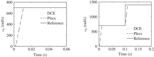
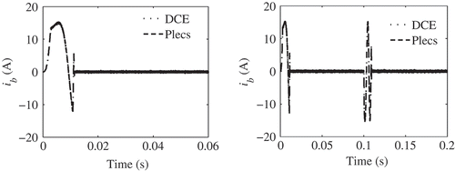
The synchronous rotor speeds and phase current ib of the PMSM are shown, respectively, in and , for both D&C Engine and Plecs. The left part of shows the key transient results when the PMSM is started up from standstill to a synchronous speed of 700 rad/s. A hysteresis current controller with a band from −0.25 to 0.25 is used. The right part of shows the speed for a 700 rad/s stepwise increase in the speed of the machine after it has run up. The corresponding phase current ib is shown in .
The results of the simulations in D&C and Plecs are not visibly distinguishable. For the constant reference value, the model in D&C Engine runs 27% faster than that in Plecs, and for the stepwise reference value 17%.
5. Conclusions
The method of modelling via transmission elements was introduced and applied to the modelling of mechatronic systems. Compared to the acausal physical modelling by using the Modelica language, it provides an alternative method to generalize the equations of complex physical systems in an iterative and numerical way. This approach was implemented in the simulation software D&C Engine, and applied to a simple circuit and a PMSM speed servo drive system.
Power converters, characterized as switch elements or their combination, are widely used in electric drive systems. To avoid the artificial stiffness and possible inaccuracy caused by the regularized switch models, ideal models are generally preferred for investigating the behaviour of electric drive systems. Because of the particular difficulties in the object-oriented modelling of ideal switches, the complete converter was modelled modularly as one object of transmission elements. The event-handling algorithm was applied to deal with the discontinuity induced by the ideal switch models.
The PMSM speed servo drive system has been modelled by using a set of objects of nodes and transmission elements in D&C Engine. Its performance-wise advantage over the signal-oriented approach, in terms of the computational time and accuracy, was presented in the attached benchmark simulation. Furthermore, the interdisciplinary nature of the modelling via transmission elements proposes the opportunity that the components or subsystems beyond the drive systems can be easily added.
As a result, the modelling via transmission elements provides a modular, easy-to-use scenario for the system development in the electric drive engineering, in which component developers may develop and test component models, while system designers may use these as building blocks per drag and drop in D&C Engine's graphical user interface (GUI) without detailed knowledge of the components. Along with the ideal models for switch elements and the event-handling algorithm, the stable, efficient and numerically accurate simulation for such systems can be achieved.
Notes
1. Modelica™ is a trademark of the Modelica Design Group.
References
- Elmqvist , H. 1978 . A structured model language for large continuous systems , Ph.D. thesis, Depart. of Automatic Control, Lund Institute of Technology .
- Kecskeméthy , A. 1993 . Objektorientierte Modellierung der Dynamik von Mehrkrpersystemen mit Hilfe von bertragungselementen , Ph.D. thesis, Universitüt Duisburg-Essen .
- Kecskeméthy , A. and Hiller , M. 1994 . An object-oriented approach for an effective formulation of multibody dynamics . Comput. Methods Appl. Mech. Eng. , 115 : 287 – 314 .
- üller , J. M and Hiller , M. A Mechatronic Simulation Model for the Large-Scale Hydraulically Driven ALDURO . Procceedings of the International Workshop on Computer Software for Design, Analysis and Control of Fluid Power Systems . Trondheim, Norway.
- Cellier , F.E. and Krebs , M. Analysis and Simulation of Variable Structure Systems Using Bond Graphs and Inline Integrations . Proceedings of the ICBGM’2007 . San Diego. California, , USA : SCS Publishing .
- Otter , M. , Elmqvist , H. and Mattsson , S.E. Hybrid Modeling in Modelica Based on the Synchronous Data Flow Principle . Proceedings of the 1999 IEEE International Symposium on Computer Aided Control System Design . pp. 151 – 157 . IEEE, , Hawaii
- Chen , Y. , Lenord , O. and Schramm , D. Modeling Discontinuous Elements in Mechatronic Systems by Using Regularized and Idealized Approaches . 4. ASIM Workshop . Wismar, Germany.
- Glocker , C.H. 2005 . Models of non-smooth switches in electrical systems . Int. J. Circuit Theory Appl. , 33 : 205 – 234 .
- Cellier , F.E. 1979 . Combined continuous/discrete system simulation by use of digital computer: Techniques and tools , Zurich, , Switzerland : Ph.D. thesis, Swiss Federal Institute of Technology .
- Hairer , E. and Wanner , G. 1991 . Solving Ordinary Differential Equations II. Stiff and Differential-Algebraic Problems , Berlin : Springer Verlag .
- Pillay , P. and Krishnan , R. 1989 . Modeling, simulation, and analysis of permanent-magnet motor drives. I. The permanent-magnet synchronous motor drive . IEEE Trans. Ind. Appl. , 25 : 265 – 273 .
- Aho , A.V. , Sethi , R. and Ullman , J.D. 1987 . Compilers. Principles, Techniques and tools , New York : Addison-Wesley .
- Allmeling , J.H. and Hammer , W.P. 1999 . “ PLECS-piece-wise linear electrical circuit simulation for Simulink ” . In Proceedings of the IEEE International Conference Power Electronics and Drive Systems Vol. 1 , 355 – 360 . IEEE, , Hongkong
- Shampine , L.F. and Reichelt , M.W. 1997 . The MATLAB ODE suite . SIAM J. Sci. Comput. , 18 : 1 – 22 .
