Abstract
Pressurized water reactor steam generators (PWR SGs) are large components whose main function is to cool the fission reactor by extracting the thermal power conveyed by the primary coolant, and thus to produce steam for the turbine generator. Tube support plate (TSP) clogging phenomena may occur in the SG when iron oxide particles carried in the secondary feedwater get unavoidably deposited inside the SG structure, and specifically in two main regions: on the U-tube outer walls and on the quatrefoil sections of the plates that support the U-tubes. They may reduce its cooling efficiency and impact its dynamic behaviour, thus leading to possible safety issues.
Methods based on local inspections of the SG have been designed and are already in use. They produce estimators of the local TSP clogging ratio, during the yearly outage of the plant for refuelling and maintenance.
A new method to assess a global estimator of the TSP clogging ratio is presented. This method is based on a 1D physical model of the SG that reproduces the complex dynamics of the two-phase flow phenomena inside the SG. The model was developed in the Modelica language.
This model is used to compute response curves of the SG characteristics to a particular transient that challenges the dynamics of the SG, when affected by TSP clogging. The estimator is obtained by comparing the computed response curves to real response curves measured on-site.
The method is still under validation. However, first results show that it is able to give global estimators that are consistent with local ones.
This new method is expected to improve the monitoring of possible TSP clogging phenomena by producing quantitative estimators with better accuracy, with a quarterly periodicity while the plant is in operation.
1. Introduction: stakes and issues
Steam generators (SGs) are key components for the operation of pressurized water reactors (PWRs): these huge heat exchangers (typically 20 m in height and 4 m in diameter) serve as a barrier between the primary system fluid which is highly radioactive (as it is heated by the nuclear fission in the reactor vessel) and the water–steam secondary system which is non-radioactive.
The main function of SGs is to transfer the heat from the primary coolant water into the secondary system to produce steam feeding the turbine.
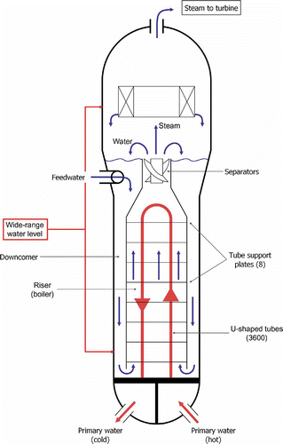
Current PWR units have 3 or 4 SGs: the secondary system feedwater is heated by the primary coolant water into steam, through 3,000 to 5,000 tubes, the exact number depending on the SG type (see ). The U-shaped tubes are about 19 mm or 22 mm in diameter depending on the SG type, and are held by 8 support plates (meant to prevent excessive vibration due to turbulent flow inside the riser).
A large component like a SG must work within given operation limits to achieve satisfactory thermal performance and acceptable lifetime: although chemistry conditions are carefully monitored, deposits will unavoidably occur with time, thus affecting SG performances.
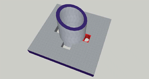
Deposits are found on the U-tube outer wall and on the tube support plates (TSP): deposits on the U-tube outer wall impact the heat-exchange capacity, and clogging deposits on the TSP will lead to the reduction of flow passage in the quatrefoil sections (see ). Such gradual drifts of the SG behaviour are very small per operation cycle, but in the end may lead to significant impact after decades of plant operation: thus they have to be monitored to help making the adequate maintenance strategies (such as chemical cleaning times).
Monitoring potential TSP clogging situations is an interesting aid to operation and maintenance strategies. This article presents possible monitoring capabilities based on modelling the static and dynamic behaviour of SGs.
So far, TSP clogging monitoring has been performed with methods used during outages (outages are periods occurring every 12–18 months, during which the plant is shutdown for periodic examination and maintenance). Non-destructive evaluation (NDE) techniques such as eddy current measurements or camera inspections allow inspection on a sampling of TSP clogging locations.
It would be a significant improvement to also provide TSP clogging estimators on the global scale of the SG, during normal operation (i.e. between two outages). Having these online quantitative indicators would help making preventive maintenance decisions, namely chemical cleaning strategies to be performed during the next outage.
Other nuclear power plant operators are tackling the subject by using empirical methods, see for example [1].
An alternative way is to use a model-based approach which to our knowledge has never been utilized before.
To that end, a model-based simulation of SG behaviour, both static and dynamic, was developed.
2. Steam generator physical behaviour
The role of the SG is to transfer heat from the primary loop to the secondary loop of the plant. The SG works as a countercurrent flow heat exchanger: the hot primary fluid coming from the reactor vessel flows inside thousands of U-shaped tubes and releases heat to the secondary fluid. On the secondary side, feedwater enters into a ring located towards the top of the tank and flows down to the bottom along the downcomer. At the bottom, it enters through a flow distribution plate into the riser, where primary/secondary loop heat exchange takes place. Water is heated up to boiling and becomes a two-phase emulsion. At the top of the riser, the ratio between the total flow and the steam flow, called the circulation ratio, is between 4 and 5 at full nominal power. The emulsion continues flowing through a first set of phase separators. The liquid separated from the emulsion is mixed with the incoming feedwater to go back along the downcomer into the riser for another round of boiling. The higher quality steam goes through a second set of separators. It leaves the SG to go to the steam turbine with a vapour quality higher than 99.75%.
3. Possible TSP clogging phenomena in SGs
Secondary system feedwater carries oxide particles, mainly resulting from iron corrosion and oxidization in the high pressure (HP) reheaters, and also from other large components such as the moisture separator reheater (MSR), and the feedwater reheater stages: magnetite particles are then preferentially trapped in the SG, on the U-tube outer walls and in the quatrefoil passages of the TSPs.
Sludge buildup eventually leads to mass flow decrease through the plates, resulting in higher void fraction inside the riser. Also, decrease in the flow cross-sectional area leads to higher fluid velocities through the TSPs, which may cause undesirable effects such as U-tube excessive vibrations and hydrodynamic instabilities.
The TSP clogging ratio is defined as
4. A model-based methodology aimed at monitoring SG TSP clogging phenomena
EDF R&D has developed an innovative method to estimate the TSP clogging ratio of each SG.
The principle is to build a 1D physical model of the SG. This model is used to process real operation data of a reference power transient that shows the alteration in dynamic behaviour of the SG because of TSP clogging. The result of the model computations is a global estimator of the TSP clogging. Here, global means that the whole SG is considered, as opposed to the local methods based on local measurements or visual inspections of a sample of U-tubes. To characterize the TSP clogging ratio, the quantity of interest is the wide-range water level (WRL) because it is sensitive to TSP clogging. The WRL is the static pressure difference between the bottom and the top of the SG (see ).
The main steps of the method are:
-
a 1D physical model of the SG is built;
-
a power transient that challenges the dynamic response of the SG is sought: this transient exists in the form of a periodic nuclear power distribution calibration of the control rods, namely a 60% power reduction in 20 minutes called EP RGL 4;
-
on-site measurement data are recorded with the plant data historian: SG-specific data (temperature, pressure, flow rates) at the inlets and outlets of both primary and secondary sides of the SG are extracted during the above-mentioned periodic test;
-
a parametric study on the TSP clogging ratio is made by feeding the characteristics of the EP RGL 4 transient into the model;
-
the computed response curves of the WRL are compared to the measured ones: this analysis is aimed at finding the curve parameters that best characterize the dynamic response of the fouled SG;
-
the best-fitted curve gives the most probable estimator.
Consequently, a dynamic SG model was developed, as described in the next section. A dynamic model is needed because the TSP clogging ratio is reflected by the delayed response of the SG behaviour to a decrease in the primary thermal power.
5. Description of the model
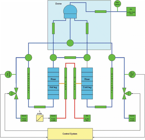
The model has three main parts: the SG itself, the boundary conditions and the SG control system.
The model developed and hereafter presented is a 51B type, typical of early 900 MW PWRs, equipping 12 three-loop units of EDF's 58 unit fleet (see [2] for a first version of the model).
5.1. Model of the steam generator
The challenge is to produce the simplest model as possible that is precise enough to account for the influence of TSP clogging on the overall behaviour of the SG.
The difficult part is the complex physical phenomena that occur within the riser. Temperature and pressure distribution in the plane section perpendicular to the main flow direction is not constant: the heat flux produced by the U-tubes decreases as the primary fluid gets cooler, so that the temperature of the emulsion is higher on the side of the riser where the primary fluid enters the U-tubes, called the hot leg, than on the other side where the primary fluid leaves the riser, called the cold leg. This phenomenon can be captured by different precision grade models, going from simple 1D mono-axial models that neglect the dissymmetry between the hot and the cold leg to full 3D CFD models that are very detailed, but CPU-time consuming.
Modelling choices must also be made to account for the pressure losses distribution along the downcomer, in the section going from the downcomer to the flow distribution plate at the bottom of the riser, through the support plate holes inside the riser and through the water/steam separators.
The following choices were made:
-
The dissymmetry between the hot and cold legs is taken into account, but there is no heat conduction between them. Each leg is modelled as a distributed tube with a wall for heat conduction between the primary and secondary fluids, and proper correlations to account for water vaporization at the wall. The flow is considered as homogeneous in each leg. More precise two-phase flow description such as the Zuber and Findlay drift-flux correlations are not used here (see [3]). These correlations take into account phase slip and non-uniform velocity and void fraction distribution across the tube. Each tube is divided into sections that represent the volumes between two consecutive support plates. The singular pressure loss because of the holes is captured by an additional pressure loss coefficient that depends upon the TSP clogging ratio. These coefficients are estimated from pressure loss measurements between the bottom and the top of the riser.
-
The downcomer is modelled as two simple adiabatic tubes, where the pressure difference between the inlet and the outlet is mainly due to gravity. Heat transfer between the riser and the downcomer, and between the downcomer and the outside is neglected.
-
The separators are modelled as a sequence of pressure losses and a two-phase water/steam cavity with water level. The water level is controlled by the SG level control system, to ensure its stability over the transients.
5.2. The boundary conditions
The objective is to reproduce the thermohydraulic conditions of the power transient at the boundary of the SG that is used to characterize the TSP clogging ratio.
On the primary side, the boundary conditions are the fluid pressure and specific enthalpy at the inlet of the U-tubes, and the mass flow at the outlet of the U-tubes. On the secondary side, the boundary conditions are the feedwater pressure and specific enthalpy at the inlet of the downcomer, and the water/steam mixture mass flow and vapour mass fraction at the outlet of the separators.
The decrease in primary power is obtained with a power ramp imposed on the fluid specific enthalpy.
The mass flow profile at the inlet of the downcomer is obtained with a control valve. The position of the valve is given by the control system, to follow the mass flow profile measured on-site.
The model was developed by interconnecting components from a power plant library developed at EDF in the Modelica language (see [4]), using the staggered grid scheme (see [5]) as shown in
5.3. Governing equations for the riser
The homogeneous model is used for two-phase flow, which means that a mixture of the two phases at equilibrium with equal velocities (no slip) is considered instead of two separate phases. However, phase slip is taken into account to compute the void fraction for the computation of the density.
The model of the riser contains the mass, momentum and energy balance equations, as shown in the following table. This table gives the distributed and lumped versions of the equations. The lumped formulations are used in the model.
Table
Notations:
-
ρ x density of the mixture
-
m_flow x mass flow
-
P x fluid pressure
-
T x fluid temperature
-
F x friction force
-
u x fluid internal specific energy
-
h x fluid specific enthalpy
-
h w,x wall/fluid heat-exchange coefficient
-
φw,x heat flux from the wall
-
z x elevation
-
v x fluid velocity
-
πw,x tube wetted perimeter
-
A x tube cross-sectional area
The subscript x refers to the location along the tube. In the lumped formulation, quantities are supposed to be constant between x and x + Δx, Δx being the step length of the discretization scheme along the tube length.
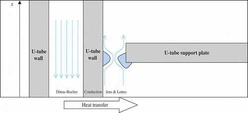
Pressure losses (friction) and heat transfer are computed using correlations (empirical formulas). The locations of these correlations are shown in
The dissymmetry between the hot and cold leg is taken into account by considering half-TSPs.
Singular pressure losses because of clogging in the holes of the support plates are given by
Heat transfer between the primary side and the U-tube wall is given by the classical Dittus–Boelter correlation (see [8]):
Heat transfer between the U-tube wall and the riser is given by the Jens and Lottes correlation:
The density of the mixture is
6. Preliminary results
Parametric studies are made for different TSP clogging ratios corresponding to different values of A i , 1 ≤ i ≤ 16. They were done using Dymola (see [10]) using the DASSL solver (see [11]). They show that the EP RGL 4 transient is fully adequate to characterize the TSP clogging ratio. Moreover, first inter-comparisons with local TSP clogging estimators are positive so far.
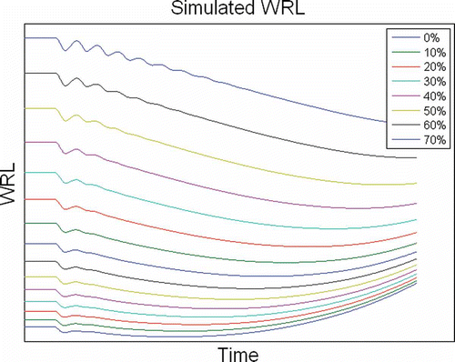
As an example, shows the results of one cross-parametric study that can be used to identify response curve parameters: response of water level with time is shown during and after a typical EP RGL4 power transient, with various TSP clogging ratios. shows a series of curves with increments of 10% of the TSP clogging ratio, but smaller increments such as 5% can be applied to improve the resolution of the method.
Figure 6. Computed curves of Figure 5 fitted against real signal. Best fit is 50% TSP clogging ratio.
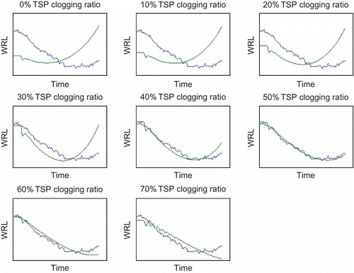
The estimation of the TSP clogging ratio is obtained by comparing the computed curves with the measured curve. The best estimate yields the TSP clogging ratio.
However, one cannot visually make a direct comparison between the computed curves WRLc and the measured curve WRLr because there are static errors in the computed curves due to the fact that the geometry of the half-SG is not strictly semi-circular and more generally because the model is not perfect. For instance, the distribution of the water inlet at the bottom of the riser is not strictly circular. Also, there are measurement uncertainties because of sensor drifts which should be eliminated. To alleviate these problems, and as the method is based on the dynamic response of the system, the curves are normalized to get rid of the static errors. For each curve, this is done by subtracting the mean value and imposing a fixed value between the minimum and the maximum values. Then the 2-norm distance between each computed curve and the real curve is computed. The best fit corresponds to the minimum distance.
Computations have been performed on 70 SGs of 900 MWe PWRs, over a 10-year period corresponding to 1500 observations. All results are compatible with the local methods, with better accuracy in the sense that the uncertainty intervals of the estimations are lower with the new method. However, validation of the new method is difficult, because it produces a global estimator that cannot be measured, so direct comparison with experiment is not feasible. For this reason, validation can only be done by thorough inspection of the method itself and by verifying that it does not give predictions incompatible with on-site observations.
7. Conclusions
A 1D physical model of the SG of a 900 MWe PWR has been presented.
By feeding the process data of a reference power transient into the model, it is possible to compute a new estimator of the TSP clogging ratio.
Other methods based on eddy current and visual inspections give local ratios every year, during the plant outage for refuelling and maintenance.
This novel method gives a global estimator that can be automatically updated every 3 months during each periodic power transient test. Therefore, a better monitoring of TSP clogging may be obtained.
First results show that the new method gives a global estimator that is coherent with the local estimators. Further validation and improvements are under way.
The model will be improved by using better heat-exchange correlations and a mesh model more adapted to the different boiling regimes in the riser. In addition, the model will be adapted to investigate 1300 MWe units.
Ongoing work consists in extending the method to give an estimation of the TSP clogging profile (i.e. the clogging parameter of each TSP).
Acknowledgements
The development of the Modelica models is a collaborative effort. Many thanks to Renaud Crinon, Frédéric Siros, Annick Souyri and Franck David from EDF for giving fruitful comments and feedback.
References
- Lee , J.Y. and Kim , H.D. 24–27 November 2008 . “ 6th Japan-Korea Symposium on Nuclear Thermal Hydraulics and Safety, NTHAS6, Okinawa ” . In Prediction of SG Tube Support Plate Flow Area Blockage from Thermal- Hydraulic Analysis 24–27 November , Japan
- Avenas , C. , Bouskela , D. , Schück , U. and Freude N. Desvignes, and O. Hascoët , T. 2004 . Quasi-2D Steam Generator Modelling with Modelica, Proceedings of Industrial Simulation Conference Malaga, , Spain
- Zuber J.A. Findlay , N. 1965 . J. Heat Transfer . Average volumetric concentration in two-phase flow systems , 87 : 453 – 468 .
- Fritzson , P. 2004 . Principles of Object-Oriented Modeling and Simulation with Modelica 2.1 , New York : Wiley IEEE Press .
- Patankar , S.V. 1980 . “ Hemisphere Publishing Corporation, Taylor & Francis ” . In Numerical Heat Transfer and Fluid Flow
- Idel'Cik , I.E. 1969 . Mémento des pertes de charge , Paris, , France : Eyrolles .
- Chisholm , D. 1973 . Int. J. Heat Mass Transfer . Pressure gradient due to friction during the flow evaporating two-phase mixture in smooth tubes and channels , 16 : 347 – 358 .
- Collier , J.G. and Thome , J.R. 1996 . “ Clarendon Press ” . In Convective Boiling and Condensation Oxford
- Chisholm , D. 1973 . Two-phase flow in pipelines and heat exchangers 304 George Godwin, , London
- Brück , D. , Elmqvist , H. , Mattsson , S.E. and Olsson , H. 18–19 March 2002 . Dymola for Multi-Engineering Modeling and Simulation, Proceedings of the 2nd International Modelica Conference, Oberpfaffenhofen 18–19 March , Germany 2002
- Petzold , L.R. 1982 . “ Sandia Report SAND82-8637, IMACS World Congress ” . In A description of DASSL: A Differential Algebraic System Solver Montreal, , Canada
