Abstract
Novel CO2 heat pump systems for domestic hot water supply are modelled using an object-oriented thermodynamic model library written in Modelica. Due to the variety of mathematical structures of thermodynamic models and the possibilities of object-oriented modelling languages, powerful libraries are often very complex and hard to understand. The scope of the presented library lies on good readability and usability for both users and model designers. The basic structure and design concepts of the library are outlined and also the most important model concepts are explained. The heat pump system is modelled and simulation results are compared with test stand measurements. Simulation results are used to analyse the design of the system and to get information about possible further improvements.
1. Introduction
Compression heat pump systems have the potential to decrease the primary energy consumption of domestic heating and hot water supply. Different studies [Citation1] have shown that heat pump systems using the natural, environmentally friendly refrigerant CO2 are able to achieve higher efficiencies than systems using conventional refrigerants when warming up heating water or potable hot water at a high temperature level (55–60°C). Thereby, new concepts of heat supply systems for low-energy buildings have resulted. Low-energy buildings are characterized by a high level of heat insulation, which leads to a reduced energy demand for heating water. However, the amount of heat required to warm up potable hot water rises compared with the overall energy demand of the building. The heating system as a whole has to supply less heat, but considered relatively, it has to deliver heat more frequently at higher temperature demands. To come close to the theoretical maximal efficiency in real systems, an accurate design is mandatory. To really lower the primary energy consumption, it is important to not only look at certain operating points but on the overall performance over long-term periods. For both aspects, simulation of heat pump systems is very useful and can support the design of heat pump systems significantly. Due to high variability of different concepts, a library with ready-to-use component models is a great advantage.
There have been many research activities about simulation of thermodynamic systems during the last decades. A variety of different programming and modelling languages are used. Richter [Citation2] gives an overview of what is state of the art in this area. The latest activities concentrate on component model libraries written in Modelica, a relatively new object-oriented equation-based modelling language. For detailed information about Modelica, see Ref. [Citation3]. The mathematical description of thermodynamic systems leads in general to non-linear equations, which are numerically difficult to solve. Different scopes of research require different levels of detail. Therefore it is useful to replace non-linear equations case-dependent by linear ones or even constants. Object-oriented modelling languages provide convenient concepts in which include this switching of levels of detail in one model. A drawback is that this often leads to very complex and hard-to-read model libraries. A short overview of state-of-the-art thermo-fluid flow modelling in Modelica is given below.
A common approach in object-oriented modelling of thermodynamic systems is to split fluid property models and component models – mostly two even separated libraries are used. The fluid property library Modelica.Medias which part of the Modelica Standard Library, uses Modelica packages to model the fluid properties of various different fluids such as ideal gas, mixtures or two-phase fluids which all inherit from one base class [Citation4,Citation5]. This library tries to combine all possible fluid models into a single framework to allow for an easy fluid property model exchange in component models. The resulting object-oriented structure is rather complex. Modelica_Fluid, developed by the Modelica Association, is a free component library for 1D thermo-fluid flow modelling [Citation4,Citation5]. It uses Modelica.Media.
The AirConditioning library is currently the most widely used library to simulate air-conditioning systems in Modelica. It is developed by the Swedish company Modelon AB and presented by Tummescheit et al. [Citation6]. The structure of the AirConditioning library is also rather complex.
In the field of dynamic power plant modelling, there is an an open Modelica library named ThermoPower [Citation7]. The main design rules for this library are quite similar to the ones described in this work. Component models are explicitly written for a type of media, water/steam or ideal gas mixtures. There is also a focus on flat inheritance structures.
In Ref. [Citation2], existing libraries are briefly examined and a new component model library is proposed with strict aims on good readability and usability. The presented library is a follow-up of the library described by Richter. A sustainable object-oriented structure is developed, which meets the demands of model developers, simulation specialists and design engineers.
2. Library
The presented library is developed and maintained by TLK-Thermo GmbH and by the Institut für Thermodynammik at TU Braunschweig. The component library is named TIL and the used media property library TILMedia. In this section, the base structure and the most important model concepts of TIL are described. The main scopes of this library are refrigeration, air-conditioning and heat pump systems. Component models for other thermodynamic systems such as steam power plants can conveniently be realized using the basic models and interfaces.
2.1. Structure
As usual in Modelica the models are sorted in packages. There are four different package types in TIL, which are indicated by different icon colours. gives an overview of the used package types.
Table 1. Different types of Modelica packages used in TIL
The object-oriented structure of TIL follows a simple set of rules developed by Richter [Citation2]. The most important ones are:
-
Inheritance should only be used if the relation between two classes can be described as an is-a-relation.
-
Multiple inheritance should be avoided whenever possible.
-
The inheritance structure should be as flat as possible.
The is-a-relation stated in the first rule has is to interpreted literally. This rule is fulfilled whenever you can build a meaningful sentence with class names A and B: a B is an A. Consider the following example from zoology. There are three different classes: Animal, Elephant and Trunk. The relation ‘an Elephant is an Animal’ does make sense, ‘an Elephant is a Trunk’ does not. In the later case, inheritance is not an intuitive object-oriented relation. But in many libraries, inheritance is used in this way to add a certain functionality to a class. ‘An Elephant has a Trunk’ sounds much more natural. Therefore the proper object-oriented way would be that the Elephant class contains an instance of the Trunk class.
These rules grew out of a detailed analysis of other state-of-the-art Modelica libraries for 1D thermo-fluid flow modelling. It turned out that too many levels of inheritance and especially multiple inheritance lead to complex structures that are hard to understand for new users. The main cause of complex object-oriented structures is identified as the ambiguous goal to have one model that can handle all different kinds of fluid property models (e.g. one tube model that can be used for compressible, incompressible, one- and two-phase fluids). That surely is a great achievement from an academic point of view, but the resulting structure and model code is very difficult to understand. TIL and TILMedia are designed in a different way. Fluid property models are distinguished into five different types as described in . There is no common base class. The component models are explicitly written for one fluid type. This approach might lead to additional lines of code, that could be saved by using inheritance, but the big benefit is better readability and sustainability. Flat structures allow new users to become familiar with the library in less time.
Table 2. Different types of fluid property models in TILMedia. The component library TIL is also sorted by this categories. Component models are explicitly written for one fluid type (heat exchangers: two media types)
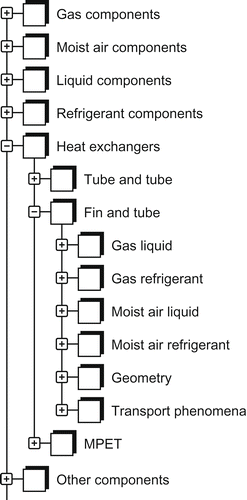
As component models are explicitly written for one fluid type, they are divided into one component package for each fluid type. A sixth top-level component package is provided for heat exchangers, because they are in general used with two different kinds of fluids. Additional component models, that do not fit in one of these categories, are located in OtherComponents. The resulting package structure is shown in .
2.2. Pressure state approximation
The mathematical description of refrigerant components is based on one major assumption: The term (time derivative of pressure) in the balance equations is treated as constant along the direction of flow for each pressure level of the system (note that it is not constant over time). Lemke [Citation8] developed this approach and showed that it is appropriate for processes that are not characterized by fast dynamics. A physical interpretation can be the neglect of sonic-effects. The Refrigerant Cell in TIL is a base model to describe a finite volume. It includes two fluid ports and one heat port. The basic equations are the mass balance:
The remaining variables in Equation1–3) are the variables at the Fluid Ports: mass flow rates and
, pressure p
a and p
b, specific enthalpies h
a and h
b, the heat flow rate at the Heat Port
, total mass M and volume V as well as the friction pressure loss Δp
f.
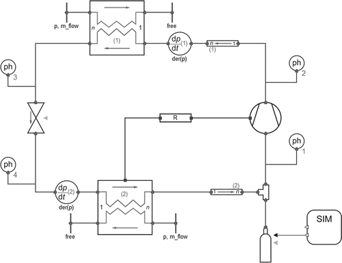
The implementation of this approach in Modelica is done by a non-physical model: the Pressure State Element. In a single-stage compression heat pump cycle, there are two main pressure levels. Therefore you can see two pressure state elements (dp/dt) in . In these components pressure is declared as differential state variable, the time derivative of pressure is propagated via the System Information Manager (see Section 2.3) to the corresponding refrigerant components. There the term in the balance equations is set to the propagated value. Technically this is done by an array of all
values, which is propagated by an inner/outer connection of all component models and the System Information Manager. A user-given integer index, which is also displayed on the graphical level (see ), defines which element of the array is relevant for each component. To fully understand the concept, the Modelica code of the Pressure State model is listed below:
Figure 2. Discretization of heat exchangers with Cells as Finite Volume Models. Different flow schemes are implementd by different connection structures.
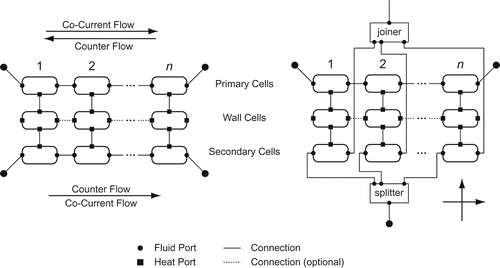
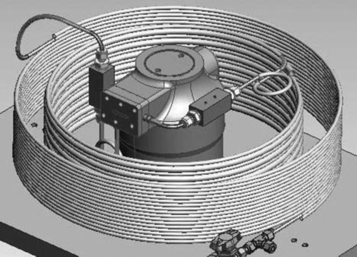
Figure 3. Concentrical construction of the CO2 heat pump. The compressor is placed in the centre – surrounded by the evaporator (inner helical tube) and gas cooler (outer helical tube).
In component models with dynamic mass and energy balance equations according to EquationEquations (1)(1) and (2), the term
is an algebraic variable, which is equal to the corresponding value of the sim object. See the following example:
It is important to understand that this does not mean that the actual time derivative of pressure is constant along the direction of flow. must be purely seen as an variable in the balance equations and not as the actual time derivative of pressure. The local pressure values result from the momentum equations and pressure loss calculations in the component models. There is only one pressure state per system pressure level. It is only for fast transients that the error is significant. The benefits are improved numerical speed because pressure is no longer a state variable in every control volume.
2.3. System information manager
Each system requires basic information including technical information (e.g. the used refrigerants, gases and liquids) as well as numerical information (e.g. the total refrigerant mass, number of pressure states) that are required for a simulation. TIL uses a component called sim of type SystemInformationManager to store all required information in one central place for each system. This component is furthermore used to compute the total refrigerant mass and the total inner volume, which are important system properties. Aggregation (Modelica: inner/outer) is used to propagate information from the system information manager to the system and vice versa. Each component model has access to the system information manager via the definition of an outer SystemInformationManager object named sim. At system level there is the corresponding inner sim object. There the user has to specify the number and names of used property models for each media type. If two or more different property models of one fluid category are used within one system, in every component model an integer parameter has to be set, that defines which one is used in this component.
2.4. Heat exchangers models
For thermodynamic systems heat exchangers usually play a very important role. In TIL heat exchangers are located in their own top-level model package. shows the library structure in the package HeatExchanger. The first internal category defines the general type of heat exchanger. In Simple you find efficiency-based models without any geometrical parameters. In the packages FinAndTube and MPET there are discretized models of fin-and-tube and multi-port-extruded-tube heat exchangers. All geometrical information of a heat exchanger is stored in one record including discretization information. The base class of this records are located in the third hierarchical level, because it only depends on the type of a heat exchanger. The same applies for transport phenomena. In this package you find heat transfer and pressure drop correlations, which are already linked to one specific geometry type. Finally the usable heat exchanger models are located in packages that define the used pair of fluids (e.g. GasRefrigerant). There are different models for different flow-patterns which all inherit from the same base class. The heat exchanger models in TubeAndTube are not much more than a wrapper class for two tube objects that are connected via their heat ports. Users can achieve exactly the same results by instantiating tubes directly and connect their heat ports.
All models with one-dimensional discretization of fluid flows (e.g. fin-and-tube heat exchangers, tubes) are based on the cell concept. Cell models describe a finite volume of a discretized model including the balance equations for mass, momentum and energy as well as replaceable heat transfer and friction pressure loss correlations. There is one model for every media category (LiquidCell, RefrigerantCell,...). These models are located in a top-level model package Cells.
The fin-and-tube heat exchanger model is the most complex model in TIL. The basic idea is to discretize the fin-side flow path and the tube-side flow path with an equal number of cells n. The distance covered by a fluid particle on its way through the heat exchanger is named path length. Path lengths are different for tube-side and fin-side flows. The fin-side path length is equal to the heat exchanger depth. In general the tube-side path length is much longer. It is equal to the length of a single tube multiplied with the pass number. Each fin-and-tube heat exchanger base model consists of n tube-side, n wall cells and n fin-side cells, as it is sketched in . This is done by instantiating arrays of cells (size n). These arrays are connected via heat ports. That means that the first fin-side cell exchanges heat with the first wall cell, which also exchanges heat with the first tube-side cell. The same applies to the second unto the nth set of cells. The MPET heat-exchanger models are quite similar to the fin-and-tube models. The pass number is fixed to one. More complex flow patterns can easily be modelled by using two or more MPET models and connecting them in the needed way.
2.5. Transport Phenomena
Pressure loss and heat transfer correlations are modelled with replaceable local models within cells (see Section 2.4). The inner/outer concept is used to make the needed cell variables available in the transport phenomena models. A PropertyRecord which is independent from the fluid type provides all needed fluid properties (e.g. temperature, pressure, viscosity). Additional variables that are also passed through by inner/outer are hydraulic mass flow rate, hydraulic heat flow rate, the wall temperature and all geometrical information which are stored in a geometry record. The type of this geometry record depends on the model it is used in. That way TIL strictly differentiates between geometry-independent transport models, which are stored in the top-level model package GeneralTransportPhenomena, and transport models that belong to a specific geometry (e.g. fin-and-tube or MPET). These models are stored in the package TransportPhenomena within the corresponding component package (see ).
3. Heat Pump System
This section describes simulation and measurement data of a CO2 heat pump system for low-energy buildings with a nominal heating power of 2 kW developed by Kosowski [Citation9].
3.1. System description
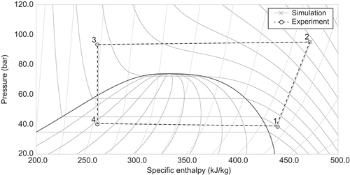
The system mainly consists of an electric compressor, two heat exchangers (evaporator and gas cooler) and an expansion valve. , which is a screenshot of the system modelled with TIL, gives an overview of the system. The thermodynamic process is shown in a ph-diagram in . Beginning at point 1 refrigerant vapour of low pressure is compressed to a supercritical pressure level (point 2). In the gas cooler, heat is transferred from the refrigerant vapour to a water flow. Instead of an isothermal condensation the heat transfer takes place with continuously falling refrigerant temperature due to the supercritical state. From point 3 cooled refrigerant vapour is expanded to the lower pressure level at point 4 entering the two-phase saturation area of vapour and liquid. Finally the cycle is closed by evaporating and superheating the refrigerant in the evaporator. The needed heat is provided by a second water flow.
An important constructional detail is illustrated in . The two heat exchangers are helical tubes that are concentrically arranged around the compressor. The inner helical tube is the evaporator the outer one is the gas cooler. Both heat exchangers are insulated with exception of the inner surface of the evaporator. The reason for this is that earlier analysis of the compressor performance have shown that the compressor releases a remarkable amount of waste heat over his casing surface. This heat is transported by radiation and convection to the evaporator and therefore increases the usable heating power. In the model diagram (), this heat flow is represented by a connection line from the compressor to the evaporator.
3.2. Measurement
Kosowski has done several test stand measurements of the CO2 heat pump system [Citation9]. The heat source and heat sink water flows are kept on constant temperatures (14°C and 25°C). The superheating of refrigerant is controlled by the valve's aperture cross section. This leads to nearly constant conditions at the evaporator. The high pressure level is varied by different total amounts of refrigerant in the system. Resulting heat flows are calculated by a water-side energy balance at the evaporator and gas cooler. The electrical power input of the compressor is measured directly.
3.3. Modelling
In the system model is shown graphically. Both heat exchangers are of the type TubeAndTube (see Section 2.4). On both sides of the gas cooler (refrigerant and water), a heat transfer correlation developed by Gnielinski (see Ref. [Citation10]) is used. The evaporator uses Gnielinski also on the water-side, the heat transfer coefficient on the refrigerant-side is set equal to a constant value. A value of 5000 W/(m2K) obtains a good fit of simulation and experimental data (see ). The compressor model is based on three efficiencies that are calculated by different measurement-based characteristic curves: volumetric efficiency, isentropic efficiency and effective isentropic efficiency. The expansion valve model is described by Bernoulli's principle for compressible flows.
3.4. Simulation results
In simulation and measurement results are plotted in a ph-diagram. The number of the state points corresponds with the number of the ph-objects in . The resulting energy flows are listed in . A good agreement of simulation and experimental data is achieved.
Table 3. Comparison of simulation and experimental results. Water-side heat flow rate at the evaporator  , water-side heat flow rate at the gas cooler
  , electrical power input of the compressor P
e
l and coefficient of performance COP
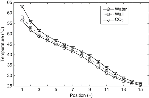
Simulation provides possibilities to analyse the process a step further. We can take a look at the temperature distributions in the heat exchangers. The cell temperature distributions of the gas cooler are plotted in . Position on the x-axis matches the cell number. The refrigerant (CO2) flows from cell 1 to 15, water flows into the opposite direction. The pinch point of the gas-cooling process lies on the water inlet. This means it would be possible to achieve a higher water outlet temperature by decreasing the water flow rate. However, the overall performance of the gas cooler is good. also illustrates a numerical issue: the number of cells must be comparable high to describe the sharp temperature profiles of supercritical CO2 cooling accurately.
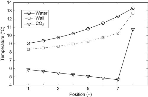
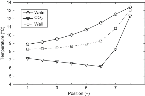
In the simulation results of the evaporator cell temperatures are plotted. Position on the x-axis matches the cell number. The refrigerant (CO2) flows from cell 1 to 8, water flows into the opposite direction. The temperature difference on the refrigerant-side is much greater compared with that on the water-side. To advance the evaporator and overall performance of the cycle, heat transfer on the refrigerant-side must be improved.
To examine which performance gain could be achieved, the refrigerant heat transfer coefficient is raised from 5000 to 10,000 W/(m2K). Superheating at the evaporator outlet is kept constant by adjusting the valve's cross section. Also the high-pressure level is kept constant by adapting the total refrigerant mass in the cycle. The simulated temperature distributions in the evaporator are shown in . Compared with the previous cycle (), the temperature difference on the refrigerant is clearly reduced. The evaporator mean temperature level is raised and with it the pressure level. As you can see in , this affects the whole cycle. Simulation results of the improved cycle are plotted in one ph-diagram together with the previous measurement-fitted simulation results. The lower pressure level increases remarkably, which lowers the needed compressor power input. The numerically resulting energy flows are listed in . Compared with previous results, the electrical power input decreases, whereas the usable heat flow rate increases for the improved cycle. This leads to a coefficient of performance (COP) gain of 3.4%. The effect on the cycle performance of an improved gas cooler heat transfer is examined in Ref. [Citation11].
Table 4. Comparison of simulation results for the improved cycle. Water-side heat flow rate at the evaporator  , water-side heat flow rate at the gas cooler
  , electrical power input of the compressor P
e
l and coefficient of performance COP
Figure 8. Simulation results of cycle with improved evaporator refrigerant-side heat transfer. Compared to previous measurement-fitted simulation.
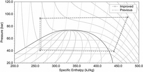
Figure 9. Distribution of cell temperatures in the evaporator, simulation results for improved cycle.
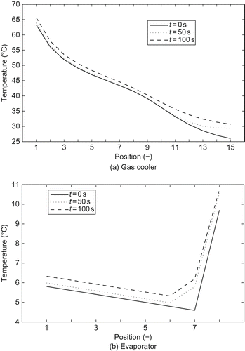
Although measurement data for this heat pump was only recorded for steady-state operating points, in simulation results are plotted, which show the transient behaviour of the system. Starting with steady-state condition there is a jump of 5 K applied to the gas cooler liquid inlet temperature at time t = 0 s. The temperature distributions of the refrigerant cells in the evaporator and gas cooler are shown at three different points in time.
Figure 10. Transient simulation results. Temperature distribution of refrigerant cells at different points in time.
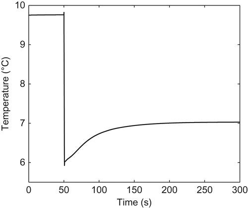
The model can also be used for control system design purposes. An important control input of vapour compression cycles is the expansion valve opening, which can be used to control the evaporator outlet temperature. In the simulated step response of this temperature is plotted. At time t = 50 s the valve opening changes from 0.111 to 0.161 mm2. The temperature immediately jumps to a lower value and asymptotically approaches an intermediate value. This behaviour is just as expected and shows that the model is well-suited for control system design.
4. Summary
The object-oriented structure of a new Modelica library for modelling of thermodynamic systems is described. The design is strictly aimed at flat inheritance structures and good readability of the resulting code. The main difference compared with other state-of-the-art libraries is that it has not tried to combine all different fluid property models (e.g. ideal gas, two-phase fluids) into one common framework. Fluid property models are distinguished into different types. Component models are explicitly written for one fluid type (e.g. refrigerants, gases). The basic model concepts of important component models are discussed. Modelling concepts for fin-and-tube heat exchangers, the most complex model in the library, are described in detail. The library is used to simulate a CO2 heat pump system for low-energy buildings. The typical requirements of low-energy buildings are low heating power at a relatively high temperature level to provide not only heating but also portable hot water. Because of the transcritical process, CO2 heat pumps have the potential to achieve higher energetic effectiveness than heat pumps using other refrigerants when delivering heat at high temperatures. The simulation results are validated by measurement data. The additional information gained by simulation is used to identify improvement potential of the system. Simulation results of an improved cycle are used to estimate the possible performance gain by improving the evaporator's refrigerant-side heat transfer. A COP increase of 3.4% results when doubling the refrigerant-side heat transfer coefficient from 5000 to 10,000 W/(m2K). In addition to steady-state simulation, the dynamic behaviour of the vapour compression cycle is shown by two simulation results: transient temperature distributions in the heat-exchangers and the response of the evaporator outlet temperature to a step jump of the expansion valve opening.
References
- Halozan , H. , Rieberer , R. and Kasper , G. Energy Efficient and Environmentally Friendly Heat Pumping Systems Using CO2 as Working Fluid-COHEPS . EU Final Report: JOE3-CT95-0006 . 1999 . Graz, Austria
- Richter , C. 2008 . Proposal of New Object-Oriented Equation-Based Model Libraries for Thermodynamic Systems , Brunswick, , Germany : Ph.D. thesis, Technische Universität Braunschweig .
- Fritzson , P. 2004 . Principles of Object-Oriented Modeling and Simulation with Modelica 2.1 , Piscataway, NI, USA : Wiley-IEEE Press .
- Elmqvist , H. , Tummescheit , H. and Otter , M. Object-Oriented Modeling of Thermo-Fluid Systems . Proceedings of 3rd International Modelica Conference, Linköping . pp. 269 – 286 . Sweden
- Casella , F. , Otter , M. , Prölß , K. , Richter , C. and Tummescheit , H. The Modelica Fluid and Media Library for Modeling of Incompressible and Compressible Thermo-Fluid Pipe Networks . Proceedings of 5th International Modelica Conference . Vienna. pp. 631 – 640 . Austria
- Tummescheit , H. , Eborn , J. and Prölß , K. AirConditioning – A Modelica Library for Dynamic Simulation of AC Systems . Proceedings of 4th International Modelica Conference, Hamburg . pp. 185 – 192 . Germany
- Casella , F. and Leva , A. 2006 . Modelling of thermo-hydraulic power generation processes using modelica . Math. Comput. Model. Dyn. Syst. , 12 ( 1 ) : 19 – 33 .
- Lemke , N. 2005 . Untersuchung zweistufiger Flüssigkeitskühler mit dem Kältemittel CO2 , DKV, Stuttgart : Forschungsbericht des Deutschen Kälte- und Klimatechnischen Vereins Nr. 73 .
- Kosowski , K. and Tegethoff , W. 2006 . “ Wärmeversorgungssystem mit CO2-Wärmepumpe ” . In Abschlussbericht DBU Förderkennzeichen Az 20866 , TU Braunschweig : Institut für Thermodynamik .
- Baehr , H.D. and Stephan , K. 1998 . Heat and Mass Transfer , Berlin : Springer .
- Kosowski , K. , Tegethoff , W. , Kühl , L. and Köhler , J. Carbon Dioxide Heat Pump Combinded with a Solar Stratified Storage Tank . Proceedings of 9th International IEA Heat Pump Conference . Zürich, Switzerland.
