Abstract
This article presents a procedure for improving the transient response of a boundary-controlled non-linear flexible elastic beam through a feed-forward action. It is shown that it is possible to obtain a formal analytic solution of an infinite-dimensional linear system, which approximates the non-linear dynamics, under time-varying boundary conditions in terms of the free vibration modes of the structure, whose calculation is a relatively easy task. The feed-forward action is then obtained by inverting the relationship between input and output variables. A numerical example is presented and some simulation results are discussed.
1. Introduction
Most control systems employ two distinct kinds of control actions: a feed-back action, to improve the stability properties of the system and increase its robustness with respect to parameters variations and/or disturbances, and a feed-forward action, usually needed to achieve a rapid response and improve tracking performances with respect to a time-varying reference signal. Designing a feed-forward controller requires, generally speaking, to invert (at least partially) the dynamics of the system to be controlled to obtain an output–input relationship which is then put in cascade with the open-loop system itself.
When dealing with infinite-dimensional systems, however, this step is not straightforward, because calculating the direct dynamics of the system in closed form may be a formidable task in itself. Even when the system has already been studied and a solution is available, usually it is developed under some assumptions that are unrealistic in control application, for example, zero boundary conditions or infinite spatial domain. Conversely, the typical effect of a control system is to introduce time-varying boundary conditions or generate a distributed action on the spatial domain. Consequently, finding an explicit expression of the final closed-loop dynamics becomes much more difficult.
This article focuses on designing a feed-forward controller for flexible beams. In robotics, this problem has been usually addressed by solving the Lagrange's inverse equation of motion in time domain. In this case, the flexible beam is a finite-dimensional system of proper order, obtained under the hypothesis that the position of a point of the link is described by a virtual rigid-body motion plus a deflection, modelled by an Euler–Bernoulli beam model with ‘some’ zero boundary conditions compatible with the rigid coordinates (e.g. clamp-free, pin-free or pin-pin) [Citation1–3].
The same problem has also been addressed in the context of flatness-based control, mainly with reference to the Euler–Bernoulli beam model [Citation4–6]. On the contrary, the procedure illustrated in this article is applied to the non-linear flexible elastic beam model introduced in [Citation7] with time-varying boundary conditions on the position/orientation of the extremities of the link and/or on the applied forces/torques. Upon linearization around the unstressed configuration, this non-linear model simplifies into the well-known Timoshenko beam model for which a formal expression of the dynamics, that is, of the solution of the partial differential equation (PDE) with time-varying boundary conditions, can be computed. This solution is expressed as an infinite series whose convergence properties, which are different from [Citation4–6], are not addressed here and are currently under investigation. Some analogies in this approach can be found in [Citation8] where a similar feed-forward control strategy for the Korteweg–De Vries equation is proposed within the flatness framework. Then, the synthesis of the feed-forward control law (i.e. the time-domain inversion of the equation of motion) is an application of the well-known results for non-minimum phase linear dynamical systems.
This article is organized as follows. In Section 2, the non-linear model of the flexible link under study is presented and it is shown that the linearization of the model around the unstressed configuration naturally leads to the Timoshenko beam model. Then, Section 3 describes a method to determine a formal solution to the equation of motion of linear beam models, with particular emphasis on the Timoshenko beam, under time-varying loading conditions. It is worth mentioning that similar results can be obtained for the Euler–Bernoulli beam. Section 4 illustrates how the application of this method generates an expression of the beam dynamics that can be easily inverted in the case of a beam constrained by a rotational joint at one end and free to move at the other. Differently from what is done in robotics, a formal expression of the solution of the PDE is computed with time-varying boundary conditions. The synthesis of the feed-forward control law (i.e. the time-domain inversion of the equation of motion) is discussed in Section 5 and turns out to be just an application of the well-established techniques developed for non-minimum phase linear dynamical systems. Here, some simulation results that show the practical validity of the method are presented. Finally, Section 6 will draw some conclusions and outline possible future developments.
2. Flexible elastic beam model
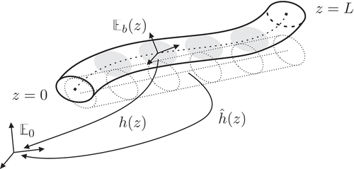
Consider a slender flexible beam of length L with an unstressed configuration that is not required to be a straight line. If denotes the position along the link in the unstressed configuration, assume that the configuration in the space of the cross section, that is, the relative configuration between a body reference
attached to the cross section and an inertial reference
, is given by
(see also ).
Figure 1. Representation of the non-linear flexible link in the deformed and unstressed configurations.
The distributed port Hamiltonian [Citation9–12] formulation of the flexible link dynamics is [Citation7]
In EquationEquation (1)(1),
and
denote the infinitesimal deformation and momentum of the cross section, and for any
describes the direction along which the unstressed configuration evolves. All these quantities are expressed in the body frame
.
is the Hamiltonian (energy) function given by the integration on
of the sum of a kinetic energy density
and a potential elastic energy density
:
Here, Y denotes the inverse of the inertia tensor I of the cross section, that is, Y = I
−1, which defines a quadratic form on se*(3), whereas C is the compliance tensor describing the (supposed linear) elastic behaviour of the link, whose inverse C
−1 defines a quadratic form on se(3) [Citation13]. Moreover, is the inner product defined by a proper metric, that is, by Y on se*(3) or by C
−1 on se(3), δ is the variational derivative [Citation12], ad is the adjoint mapping on se(3), that is,
being
the Lie bracket in the algebra [Citation14], whereas
[Citation15]. Finally,
. It is clear, then, that the boundary terms in EquationEquation (2)
(2) are simply the generalized velocities (i.e.
) and forces (i.e.
) at the extremities of the beam (i.e. in z = 0 and z = L).
In the case of planar motion, for example, on the x–y plane of the inertial reference , and under the hypothesis that the unstressed configuration of the beam is a line in the x-direction of the body reference
, it is easy to verify that the linearization of EquationEquation (1)
(1) results into a transverse wave equation in the displacements in the x-direction, and in the following PDE:
In [Citation16], it has been proved that EquationEquation (4)(4) is the port Hamiltonian formulation of the Timoshenko beam equation, where ρ is the mass density, E and G are, respectively, the Young's and shear moduli, A is the cross-sectional area, I is the area moment of the cross section and k is the shear factor used to calculate the transverse shear stiffness of the beam. In the literature, several values for this coefficient have been proposed. This article uses the derivation of [Citation17], which corresponds (assuming a rectangular cross section) to a value of k = 0.85. If written in terms of the deflection of the beam w(z, t) and of the angle of rotation of the cross section ψ(z, t), EquationEquation (4)
(4) transforms into [Citation18]
3. General solutions of the Timoshenko beam equation
Let us now consider a beam whose dynamics is described in EquationEquation (5)(5). The usual way to deal with time-varying forcing actions is to assume the existence of a solution y in the form
, then Laplace transform the PDE to ‘get rid’ of the time derivatives and obtain an ordinary differential equation (ODE) in the spatial variable z. Once this equation is solved, its reverse Laplace transform yields the solution sought. This approach has been adopted in [Citation19] and more recently, in the context of feed-forward control design, by [Citation20]. The main limitation of this method is that finding a reverse Laplace transform of an arbitrary function could be quite difficult and moreover, in case the loading condition changes, another inverse transform must be calculated.
On the contrary, this article follows the strategy described in [Citation21,Citation22] showing that it is possible to obtain formal solutions for forced motions of beams through superposition of the modes of the associated homogeneous problem (i.e. the problem where all boundary conditions are set to zero). The method is based on very classical results and it is now well-known under different variations and names in mechanics, for example, assumed modes or Rayleight–Ritz methods. Generally speaking, it is applicable under the following assumptions:
| • | The PDE describing the system dynamics is linear and | ||||
| • | The modes obtained by solving the homogeneous problem form a complete set. | ||||
This reduces at calculating the forced response of the system to the solution of an eigenvalue problem (a simple, albeit somewhat tedious task). Moreover, once a given set of modes is known, it is possible to derive quite easily the system dynamics for any input–output combination corresponding to the boundary conditions chosen. Let us assume that external forces may act on the system only through the boundary conditions, which will be expressed by means of the following differential operators:
Once a set of boundary conditions has been chosen among EquationEquation (6)(6) and the initial conditions w(z, 0),
, 0), ψ(z, 0) and
, 0) have been assigned, the solution of EquationEquation (5)
(5) exists and is unique.
Let us also assume to have solved the associated homogeneous problem, that is, we know the sequence of eigenfrequencies ω n and the associated modal shapes Wn (z) and Ψ n (z) such that
Let us now tackle the case of forced vibrations, that is, can be time-varying. The solution of this problem will be sought in the following form:
The solution of EquationEquation (11)(11) is given by
4. Feed-forward action for the rotating Timoshenko beam
Let us now focus on a more specific example, a beam which is constrained to rotate thanks to a pin joint located at z = 0. Let that point be the origin of a horizontal plane where the motion takes place and let the forcing action be a torque τ
q
(t) applied to the joint. To use such a model, it is necessary to devise a way to include the rigid-body mode of rotation into the beam model. One of the simplest way is to define θ as the weighted average angle of inclination through the origin (to be defined more precisely by EquationEquation (17)(17)) and to assume that any longitudinal elongation and stress of the beam due to rotation is small and may be neglected.
By denoting with (z, w) the position vector of a point of the centre line of the beam at distance z from the origin, expressed in the moving frame associated with the beam, and with the corresponding quantities in the fixed reference frame, it has been proved in [Citation23] that the dynamic model expressed in the fixed frame has the same form as EquationEquation (5)
(5), provided that we set
It is now possible to work out the solution of the rotating beam problem: Let the input signal of our system be and the output to be controlled by the tip position, that is,
. The prescribed boundary conditions are
The next step deals with the solution of the eigenvalue problem to find the numerical values of the resonant frequencies ω
n
and the expressions of the modal shapes Wn
and Ψ
n
. To avoid dealing with cumbersome coefficients and expressions, we shall use the parametrization of [Citation24] in the following passages, as reported in . By assuming that the solution of the homogeneous problem is EquationEquation (7)(7), it is possible to obtain a set of ODEs whose solution is not identically zero only for some values of the frequency ω
n
. After a lengthy but straightforward calculation, it can be shown that such frequencies can be obtained as solutions of the equation:
Table 1. Variable correspondence for the eigenvalue problem [Citation24]
Now, by combining EquationEquations (8)(8), Equation(10)
(10) and Equation(14)
(14) and by assuming zero initial conditions and that at t = 0 no forcing action is present, in the light of EquationEquations (15)
(15) and Equation(18)
(18), a particularly simple expression is obtained for
:
By recalling EquationEquation (16)(16) and applying the Laplace transform to the whole expression, we finally get
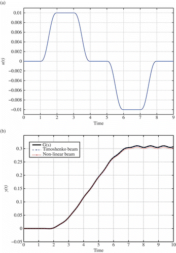
The accuracy of the approximated solution obtained by truncating the terms in EquationEquation (25)(25) to Nm
has been analysed with reference to a beam with unitary length, with
,
and
, and with square cross section of side 0.01 m. A model of this rotating beam was developed using ABAQUS FEA© (by SIMULA), a software package used for finite-element (FE) analysis. The beam geometry was meshed using 100 B22 elements, that is, 3-node planar beam elements with quadratic interpolation derived using Timoshenko's theory. The number of the elements used is overwhelmingly more than the strict necessary, but the objective here is to obtain a virtual prototype of the beam, which can be used to validate the finite-dimensional approximation
.
The FE model thus obtained first underwent an analysis step of frequency extraction. By looking at the participation factors (see ), which indicate how much each mode ‘participates’ in the final vibration, it is possible to estimate that not more than 4 or 5 modes will dominate the system response. The actual values of the eigenfrequencies and the modal shapes have also been compared to those obtained analytically from EquationEquations (20)(20) and Equation(21)
(21) to make sure they matched. Then, two steps of dynamic simulation using the implicit solver ABAQUS/Standard to observe the beam response to a specified control input (see (a)) were performed. The dynamic analysis carried out was performed first by suppressing non-linear effects due to large deformations to simulate exactly a Timoshenko beam model (which is based on a linearization of the equation of the elasticity), and then by including them. At the same time, the transfer function of the beam in EquationEquation (25)
(25) was approximated by setting Nm
= 4 and the response under the same control input was computed. A comparison of the results obtained is presented in (b). It can be seen that
and the linearized FE model yield practically identical responses, as expected. Actually, by taking into account the bandwidth of the smooth signal u(t), it can be seen that also truncating at Nm
= 2 produces basically the same results. The behaviour of the full non-linear model is instead slightly different, and this is due to both the limitation of the Timoshenko model itself and the approximations in EquationEquation (15)
(15) that were used to introduce the rigid-body mode.
Table 2. Natural frequencies of the beam
Figure 2. Comparison between the response provided by and the FE models. (a) Input signal u(t). (b) The beam response y(t).
5. Control design and simulation results
In this section, a possible solution for the synthesis of the feed-forward control action that takes advantage from the formal solution of the equation of motions computed in the previous section is presented, together with some simulation results that prove the practical validity of the approach. The design of the control unit relies on the inversion of the finite-dimensional approximation (25). This step becomes more complicated as the transfer function so obtained is non-minimum phase. This is a common characteristic of the beam models that assume EquationEquation (18)(18) as boundary condition. Generally speaking, this means that the compensator will be only an approximation of the inverse dynamics, which would be otherwise unstable.
It is outside the scope of this article to review all the techniques investigated in the literature to compute a non-causal inverse of a linear system and so we shall focus on a specific solution proposed by [Citation25] which is based on the so-called steering along zeros control (SAZC) strategy by [Citation26]. This method assumes the plant to be controlled to be a discrete-time system, but this is not particularly restrictive. Because most implementations of control units are digital, this simply means approaching the synthesis problem by directly working on a discretized model of the system rather than designing a continuous-time regulator that must be discretized later.
Let us denote the discrete-time model of the system, obtained in this example by a matched pole/zero discretization method with a sampling time of 0.005 s. Furthermore, let
, where Nu
(z) is made up by the unstable zeros of Gd
(z), whereas N s
(z) contains the stable ones. Note that this is equivalent to require that Gd
(z) has no zeros on the unit circle. This is a rather strong assumption that will be discussed later.
The control scheme is shown in . As it can be seen, the feed-forward action is decomposed into two contributions: the first one, , is the standard inversion of the minimum phase dynamics whereas the second one,
, is designed to steer the state of the system (for t < t
0, the instant when the reference motion starts) towards a suitable initial state that guarantees perfect tracking with bounded control signals. In practice, only an approximate inverse can be computed as the exact solution of this problem would require infinite pre-action time, so the convolution of unstable zeros in the reverse time direction is truncated after a finite number of samples k
pre. The delay z
−d
takes into account the relative degree d of Gd
(z) and the feed-back regulator Rd
(z) is necessary to provide the necessary robustness to the system in case of external disturbances and not perfect knowledge of the parameters of the link, which is always the case in practical applications.
Figure 3. The control setup.
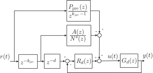
The unknown polynomials in can be determined, once k pre has been chosen, by solving two Diophantine equations:
Note that EquationEquation (26)(26) is correct if N(z) is monic, otherwise an additional gain must be incorporated in the controller.
Even if this kind of controller is quite easy to design, its working principle requires the zero-dynamics to be asymptotically converging to zero, either in forward or in reverse time. There is nothing, however, preventing Gd
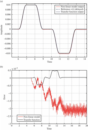
(z) from having zeros on the unit circle and, in fact, the transfer function of this example exhibits this feature. A simple yet effective way around this problem is to consider a ‘perturbed’ output , defined as
shows the result of using the control input of the previous test as reference signal r(t) to the feed-forward controller of , assuming k pre = 1000 and ε = −0.001. As can be seen, it is possible to drive quite accurately Gd (z), the FE model is more sensitive to the approximations introduced in the controller design and its output error tends to increase over time.
Figure 4. Tracking performances with feed-forward unit only. (a) The beam response y(t). (b) Tracking error.
It is arguable that the control problem examined until now is somewhat unrealistic, as pure open-loop control of such a system would be possible in simulation only. Moreover, as it turned out, even then the performances could not be up to the expectations, if ‘enough pathologies’ arise. A more complete application would of course include also the feed-back controller Rd (z) (see ), to correct the approximations of the feed-forward action and provide robustness to the system. A number of solutions have been proposed in the literature to design feed-back regulators of flexible beams based on their infinite-dimensional model (see, e.g. [Citation28] or [Citation16]). In this case, however, assuming that the feed-forward controller yields an accurate description of the inverse dynamics, it is also possible to resort to a quite simple control unit (a ‘low-authority’ controller) just to provide the small corrections that may be needed.
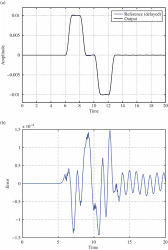
A final simulation has therefore been made by including a digital PD controller with low gains. Using a proportional gain of 0.55 and a derivative gain of 0.001, the results are plotted in . Now the feed-back action intervenes by eliminating the drift that could be seen in the previous simulation and reduces the overall magnitude of the tracking error.
Figure 5. Tracking performances with feed-back and feed-forward units. (a) The beam response y(t). (b) Tracking error.
6. Conclusions and future work
6.1. Conclusions
In this article, a procedure to determine a feed-forward controller for a non-linear flexible link model based on its linearization around the unstressed configurations turns out to be the Timoshenko beam model. Its key feature is to bring a potentially difficult problem, such as determining an analytic input–output relationship in the presence of time-varying boundary conditions and distributed forcing actions, within the well-known framework of modal analysis and polynomial transfer functions. The analytic solution in turn provides a complete understanding of the assumptions that can be made without neglecting relevant dynamics and enables the reuse of a variety of techniques coming from linear system theory on the resulting approximate model. A simple, yet significant example of the use of such method is presented in the second half of this article, together with a numerical example and simulation results.
6.2. Future work
Main theoretical issue to be tackled is to find the conditions under which the formal solution of the force beam equation, expressed by the series EquationEquation (10)(10), converges. Besides the intrinsic theoretical contribution, this result would have a noticeable impact also on the practical implementation of the control method itself. Moreover, because the focus of this article was deriving feed-forward controllers and the model of reference for the example was a non-linear beam model that turns out to behave as the Timoshenko beam for small deformations, some issues such as the presence of friction and sensor/actuator disturbances have been ignored by making use of a virtual prototype based on FE technology. Further investigations that could require the use of experimental set-ups should take into account these problems, most likely by a more careful design of the feed-back controller.
Another interesting line of development would be extending the procedure to other infinite-dimensional models besides beams. On the one hand, the technique used to obtain the analytic solution is fairly general and could be applied also to other kinds of PDEs. On the other hand, the previously examined example could be seen as a ‘building block’ for a more general approach for planning the motion of flexible multi-body systems. In fact, even if by itself the rotating beam is just a trivial one degree of freedom manipulator, the way the load influence is taken into account into the solution could be exploited to obtain the model of a complex structure from the modular composition of different beams.
Acknowledgement
The authors wish to gratefully thank Prof. Lorenzo Marconi (DEIS, University of Bologna) for the fruitful discussion and the precious suggestions on the control design procedure illustrated in Section 5.
References
- Bemosman , M. and Le Vey , G. 2004 . Control of flexible manipulators: A survey . Robotica , 22 : 533 – 545 .
- De Luca , A. 1996 . “ Flexible links ” . In Theory of Robot Control , Edited by: de Wit , C. , Siciliano , B. and Bastin , G. 219 – 261 . New York : Springer .
- Kwon , D.S. and Book , W.J. 1994 . A time-domain inverse dynamic tracking control of a single-link flexible manipulator . ASME J. Dyn. Syst. Meas. Control , 116 : 193 – 200 .
- Meurer , T. , Kugi , A. and Thull , D. 2008 . Flatness-based tracking control of a piezoactuated Euler-Bernoulli beam with non-collocated output feedback: Theory and experiments . Int. J. Control , 81 : 473 – 491 .
- Meurer , T. and Kugi , A. 2009 . Tracking control for boundary controlled parabolic PDEs with varying parameters: Combining backstepping and differential flatness . Automatica , 45 : 1182 – 1194 .
- Rouchon , P. 2001 . Motion planning, equivalence, infinite dimensional systems . Int. J. Appl. Math. Comp. Sci. , 11 : 165 – 168 .
- Macchelli , A. , Melchiorri , C. and Stramigioli , S. 2007 . Port-based modeling of a flexible link . IEEE Trans. Robot. , 23 : 650 – 660 .
- Laroche , B. and Martin , P. 2002 . Motion planning for a linearized Korteweg–De Vries equation with boundary control . Proceeding of the 15th, IFAC World Congress . Spain, July 2002 , Barcelona. pp. 225 – 230 .
- Maschke , B.M. and van der Schaft , A.J. 1992 . Port controlled Hamiltonian systems: Modeling origins and system theoretic properties . Nonlinear Control Systems (NOLCOS 1992), Proceedings of the 3rd IFAC Symposium . June 1992 , Bordeaux, France. pp. 282 – 288 .
- van der Schaft , A.J. 2000 . “ L2-Gain and Passivity Techniques in Nonlinear Control ” . In Communication and Control Engineering , New York : Springer–Verlag .
- Duindam , V. , Macchelli , A. , Stramigioli , S. and Bruyninckx , H. , eds. 2009 . Modeling and Control of Complex Physical Systems. The Port-Hamiltonian Approach , New York : Springer .
- van der Schaft , A.J. and Maschke , B.M. 2002 . Hamiltonian formulation of distributed parameter systems with boundary energy flow . J. Geo. Phys. , 42 : 166 – 194 .
- Selig , J.M. and Ding , X. 2001 . A screw theory of static beams . Intelligent Robots and Systems (IROS 2001), Proceedings of the IEEE/RSJ International Conference . October 29 2001 , Maui, HI. Vol. 1 , November 3 . pp. 312 – 317 .
- Selig , J.M. 2005 . “ Geometric Fundamentals of Robotics ” . In Monographs in Computer Science , 2nd , New York : Springer .
- Stramigioli , S. 2001 . “ Modeling and IPC Control of Interactive Mechanical Systems: A Coordinate Free Approach ” . In Lecture Notes in Control and Information Sciences , 1st , London : Springer .
- Macchelli , A. and Melchiorri , C. 2004 . Modeling and control of the timoshenko beam. The distributed Port-Hamiltonian approach . SIAM Journal of Control and Optimization , 43 : 743 – 767 .
- Cowper , R.G. 1966 . The shear coefficient in Timoshenko's beam theory . ASME J. Appl. Mech. , 33 : 335 – 340 .
- Timoshenko , S. 1935 . Vibration Problems in Engineering , 2nd , New York : Van Nostrand Company Inc .
- Boley , B.A. and Chao , C.C. 1955 . Some solutions of the Timoshenko beam equations . ASME J. Appl. Mech. , 77 : 579 – 586 .
- Rudolph , J. and Woittennek , F. 2003 . Flachheitsbasierte steuerung eines Timoshenko-balkens . Z. Angew. Math. Mech. (ZAMM) , 83 : 119 – 127 .
- Herrmann , G. 1955 . Forced motions of Timoshenko beams . ASME J. Appl. Mech. , 77 : 53 – 56 .
- Mindlin , R.D. and Goodman , L.E. 1950 . Beam vibrations with time-dependent boundary conditions . ASME J. Appl. Mech. , 72 : 377 – 380 .
- Taylor , S.W. and Yau , S.C.B. 2003 . Boundary control of a rotating Timoshenko beam . ANZIAM J. , 44 : E143 – E184 .
- Huang , T.C. 1961 . The effect of rotatory inertia and of shear deformation on the frequency and normal mode equations of uniform beams with simple end conditions . ASME J. Appl. Mech. , 28 : 579 – 584 .
- Marconi , L. , Marro , G. and Melchiorri , C. 2001 . A solution technique for almost perfect tracking of nonminimum-phase, discrete-time linear systems . Int. J. Control , 74 : 496 – 506 .
- Marro , G. 1996 . “ LNCIS, multivariable regulation in geometric terms: Old and new results ” . In Colloquium on Automatic Control , Edited by: Bonivento , C. , Marro , G. and Zanasi , R. New York : Springer–Verlag .
- Geniele , H. , Patel , R.V. and Khorasani , K. Control of a flexible-link manipulator . Robotics and Automation (ICRA 1995), Proceedings of the IEEE International Conference . May , Nagoya, Japan. Vol. 1 , pp. 1217 – 1222 .
- Luo , Z.H. , Guo , B.Z. and Morgul , O. 1999 . Stability and Stabilization of Infinite Dimensional Systems with Applications , London : Springer–Verlag .