Abstract
A dynamic model of a through-air-drying process for viscose staple fibres is presented in this article. In this process fibres formed to a porous web are transported through a convective dryer that consists of numerous rotating drum sieves. Finally, the fibres pass through two remoistening drums. The structure of the model is modular and scalable. On applying spatial discretization the originally partial differential system equations (conservation of mass and energy) turn into a system of ordinary differential equations. Drying rates and heat transfer rates are calculated using phenomenological equations for heat and mass transfer. Kinetics of drying is separated into three phases, where viscose fibres are hygroscopic. The process model is able to simulate transient behaviour of the dryer like changes of the incoming fibre moisture, changes of the drying air temperature and humidity and changes of the thickness of fibre layer on the drums. Stationary validation of the longitudinal fibre moisture distribution along the dryer shows good accordance with measurement data at different operating points, for example, different temperature profiles. Dynamic data like temperature transients are utilized for both model fitting and validation of the dynamic model. For the remoistening process and disturbance behaviour concerning the thickness of the fibre web, black box models have been identified. Results of a successful application of the model in a predictive control algorithm are shown.
1. Introduction
Convective through-air drying is a highly efficient state-of-the-art drying technology in the paper and textile industry. The technique is applied in processes to remove moisture from porous media and bulk goods. It features an intense contact between drying air and the good to be dried. Therefore, high rates of simultaneous heat and mass transfer can be obtained [Citation1,Citation2].
The goal of this investigation was to construct a mathematical model of an industrial drying process for viscose staple fibres, which is suitable for design of a model predictive controller (MPC). In this thermal process a belt of fibrous web is carried on the surface of the so-called rotating drum sieves through the dryer (see ). Due to this dryer construction, the transportation path of the web is shaped like a meander. While being carried through the dryer, heated air is sucked through the web by means of ventilators. After passing through the web, the drying air is heated up again at each drum by heat exchangers that are fed with steam or hot water. The dryer is divided in heating zones, which consist of three to four drying drums. Therefore, it is possible to expose the fibres to a desired temperature profile in order to obtain an optimal product quality and moisture setting.
Figure 1. Scheme of the dryer: the transportation path of the fibre belt and the flow directions of the drying air are indicated as well as the insertion of water and the moisture measurement.

This type of dryer can consist of numerous drums up to a number of 20 and even more. In the process considered here, the loose fibre flakes enter the pre-dryer (8 sieve drums) forming the fibrous web followed by the main dryer (16 sieve drums). Both the pre-dryer and the main dryer are operated in counter-current flow with separated air feeds. This means that each of the two parts of the dryer is fed with fresh air from the factory building, which is not preconditioned. shows a scheme of the dryer and indicates the mass flows of fibres and air. Differently shaded areas represent the heating zones. At the end of the process, the fibre belt passes two remoistening drums, where preconditioned humid air flows through the fibre web, and consequently a sorption equilibrium between the fibres and the humid air is established. The procedure of slightly remoistening the fibres is used to obtain a higher homogeneity of the desired moisture at the end of the process. After remoistening the fibres, they are transported pneumatically to the bale press. This also can influence the fibre moisture setting noticeably depending on the relative humidity of the transportation air, which is also not conditioned.
There exist a lot of publications on the general through-air-drying process. Most of them refer to paper drying and modelling of that process, for example, [Citation3,Citation4], but there exists no literature specifically about modelling of drying processes for viscose staple fibres in a drying process with distributed drum sieves.
Literature about first-principle models for drying processes abounds, since drying, including the phenomena of diffusion and heat transfer, is a very fundamental operation [Citation1,Citation2,Citation5–7]. When it comes to fibre drying, publications are mainly addressing models for the drying process in paper industry. Basically, physical phenomena like the effect of pore size distribution on the drying rate in tissue paper are modelled [Citation8]. Publication [Citation9] focuses on the effect of permeability of towel and tissue during the drying process. In [Citation10] a semi-theoretical and empirical approach of Fick's second law for thin-layer drying in food industry is presented. Another model for medium density fibreboard (MDF) fibre drying in a tube dryer is presented in [Citation11]. Modelling of a convective rotary dryer in the agricultural sector is presented in [Citation12]. In [Citation13] a drying model for acetate fibre is presented, but since the fibre is a filament, the drying process is quite different than for a fibre sheet. A general paper about modelling methods is given by [Citation14], with specific details concerning pore networks and population balances in fluidized bed drying.
There are two main contributions of this article:
| • | A new overall model of viscose fibre drying with through-air-drying drums, derived specifically for implementation in control applications. | ||||
| • | A modular and scalable model structure that can be adapted to different industrial realizations of this drying process. | ||||
The model considers the main effects of varying drying kinetics, but its primary goal is also to be effective and suitable for the control algorithm in which the model is to be applied. Therefore, the model parameters can easily be fitted to new process variants. The overall model results to be a grey-box model, since some process dynamics are difficult to obtain by physical modelling due to hardly known physical parameters, and therefore, black-box models are identified from measurement data.
2. Modelling
2.1. Model inputs, outputs and parameters
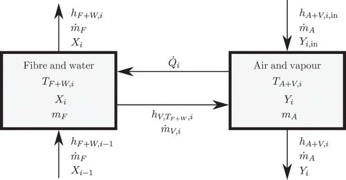
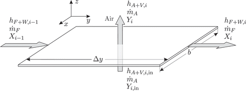
The following relevant process values are included and therefore regarded in the model of a discretized drum module with index i and are denominated as follows (see also ):
Figure 2. Scheme of a plane fibre web element with index i: X moisture content in the fibres, Y humidity of air, m
F
mass of dry fibres, mA
mass of dry air, mass flow of dry fibres,
mass flow of dry air,
actual mass flow of evaporating water, and h specific enthalpy. Subscript A stands for air, V for vapour, i for element index, and in for the respective input value.
| 1. | Input values
| ||||||||||||||||||||||||||||||||||||||||||||||||||||
| 2. | Output values
| ||||||||||||||||||||||||||||||||||||||||||||||||||||
| 3. | Process parameters
| ||||||||||||||||||||||||||||||||||||||||||||||||||||
The classification of the process values to input values, output values and process parameters is more or less arbitrary. Both input values and process parameters are data that need to be known in order to be able to simulate the drying process. In this case, the input values are process values that are likely to change during the drying process and therefore of special interest for investigations. They are visible and easily changeable in the graphical user interface of the model's software implementation to perform simulations with different set-ups. Input values are also inputs to the real process so they have a great influence on the drying behaviour and can also be considered to be used as control variables.
The drying model should be able to simulate transient behaviour of the process like changes of the incoming fibre moisture, changes of the drying air temperature and humidity and changes of the thickness of the web of viscose fibres.
2.2. Model structure
The structure of the desired model is modular and scalable. This means that a model of a single drum sieve dryer with lumped parameters is established, which enables the simple adaptation of parameters like geometrical values and process or plant parameters. By joining several of these modules, it is possible to model the whole drying process. The main equations of the model are balance equations of mass and energy that generally leads to partial differential equations (system with distributed parameters). In order to obtain a system with lumped parameters, the model is spatially discretized. This ensures that the equations turn into a set of common differential equations that can be solved numerically.
As mentioned before, the dryer consists of 26 sieve drums. The radius of a drum is 0.7 m and the width about b = 1.5 m, so the entire length of the fibre belt inside the dryer is about L = 60 m. With an approximate average speed of 0.25 m s−1, variations depending on the fibre type, the residence time of the fibres is about 3 minutes. The mass flow of drying air is 16 kg s−1 and assumed to be constant for all heating zones. The porosity of the fibre web is estimated to be ϵ = 0.9 and the incoming fibre moisture after mechanical dewatering is about 100% in terms of weight.
The dryer with 26 drums was discretized into 26 elements, so one sieve drum constitutes a discrete module. As a consequence one discrete element of fibre web has a length of approximately Δy = 2.2 m. This relatively coarse discretization was chosen due to the model's use in an online calculation for an MPC controller. Because of the small thickness d = 0.02 – 0.04 m of the fibre web compared to the radius of the drum, the assumption of a plane transportation path was made, so one fibre web element has the volume of a cuboid. As the validation and the MPC performance shows, these structural assumptions were justified.
2.3. Model equations
2.3.1. Assumptions
The following assumptions for the system are made:
| 1. | Diffusion in the fibre web is homogenous. | ||||
| 2. | There exists a thermal equilibrium between the fibre and liquid water phase, so there are no temperature gradients. | ||||
| 3. | Drying air flow is homogenous. | ||||
| 4. | Advection (water transport due to bulk motion of fibre web or drying air [Citation6,Citation15]) is at least 2 orders of magnitude larger than diffusion (water transport within the fibre web). | ||||
| 5. | Water is not transported across the lateral boundaries (x-direction) of the fibre belt. | ||||
| 6. | The humidity of the fibre at the process input is homogenous in x- and z-directions. | ||||
2.3.2. Partial differential equations
Assumption 2 leads to the consequence that there is neither heat transfer between these phases nor heat conduction through these phases, and for the temperatures T[°C] follows:
where the subscripts F and W stand for fibre and water, respectively.
The general mass balance EquationEquation (2)(2) of the water content
for the fibre web can basically be expressed by Fick's second law [Citation6], an advection term [Citation6,Citation15], and the evaporation rate
where v F (m s−1) denotes the velocity field of the fibres and DWF (m2s−1) is the diffusion coefficient [Citation2,Citation6]. mF (kg) is the mass of dry fibres in one model element and can be expressed as
where ρ F (kg m−3), the density of dry fibre, is treated as a constant. V(m3) is the volume of the model element and ϵ[–] the bulk porosity.
Because of Assumptions 5 and 6 (no diffusion in x- and z-directions) EquationEquation (2)(2) can be simplified to
EquationEquation (4)(4) states that only longitudinal variations in humidity are considered by the model. The following initial and boundary conditions must hold for EquationEquation (4)
(4):
Note that mixed boundary conditions apply (Dirichlet and Neumann conditions on different boundaries [Citation5,Citation15]); at the process input (y = 0) the time-varying humidity X
0(t) is effective while at the process output (y = L) the gradient in y-direction vanishes.
Analogously, the general mass balance of vapour content Y in the drying air is given by
where DVA (m2s−1) is the diffusion coefficient of vapour in air and v A denotes the velocity field of the air. In the case of vapour, gradients in x-direction vanish and the velocity has only a component in z-direction:
Initial and boundary conditions for the humidity in air are given by
2.3.3. Spatial discretization
EquationEquation (4)(4) for the overall fibre belt is spatially discretized in y-direction into consecutive web elements of equal length Δy (note that Δy corresponds to the length of fibre web in one dryer module). In a scheme of the ith plane fibre web element with its incoming and outgoing mass- and energy flows is shown, where X(kg kg−1) is the moisture content in the fibres, Y(kg kg−1) the humidity of air, mA
(kg) the mass of dry air,
the mass flow of dry fibres,
the mass flow of dry air,
the actual mass flow of evaporating water and h(J kg−1) the specific enthalpy. The subscript A stands for air, V for vapour, i for the index of the element, and in for the input variables.
In the interactions between inputs, outputs and inner states of a single fibre web element are shown. The advection term is given in discretized form by
and each element of the fibre web is described by the following first-order ordinary differential equation (note that due to Assumption 4):
EquationEquation (16)(16) describes the mass balance of water in the fibres of one element. It is a non-linear differential equation, since the evaporation rate
is dependent on the actual moisture setting Xi
of the fibres, like shown in EquationEquations (28)
(28) and Equation(29)
(29), and it is also non-linear in the parameters, because the properties of all media are temperature dependent. Note also that the moisture input to each element i by advection is given by the moisture output of the previous element i − 1. Only the very first element has the input X
0(t) as given in (6).
In the gas phase of each element due to Assumptions 3 and 4 and
, and EquationEquation (9)
(9) is approximated by
where is the mass of dry air in one model element, and the density of dry air ρ
A
(kg m−3) is temperature dependent. From the air-path (see ) follows that for most elements
holds, only the for last elements of predryer and main dryer, respectively,
holds, where Ya
denotes the humidity of ambient air.
For convenience, the energy balances for the solid/liquid phase and for the gas phase are only stated in their discretized form. EquationEquation (18)(18) shows the energy balance for fibre and water in element i:
is the transferred heat flow from air to the fibre sheet and the
are the specific heat capacities of the respective media. The specific enthalpy of vapour generally can be expressed as in EquationEquation (19)
(19) where Δhv
(J kg−1) is the (constant) enthalpy of evaporation:
EquationEquation (20)(20) represents the energy balance for air and vapour:
Remark 1:
The coupling between the first-order differential Equation16–18) and (Equation20(20)) is given by the mass flow of evaporated water
, the heat exchange between phases
and the humidity of fibre Xi
and air Yi
.
The coupling between element i and adjacent elements is constituted by the input of humid fibre from the preceding element with temperature
and drying air from the subsequent element
with temperature
.
Remark 2:
Due to the match of element length and dryer module size (see and ) the air flow through one fibre web element will be almost homogenous, thus justifying . On the other hand, gradients
,
,
and
are certainly not equal to 0. Although the thickness of the fibre web element d is much smaller than the discretization length Δy strong gradients in z-direction exist.
If a locally more accurate solution for is sought for, the discretization length Δy should be reduced and a discretization in z-direction must be considered. Another approach would be the use of finite-element (FE) methods [Citation16], where polynomial or exponential basis functions would allow for high accuracy even with coarse discretization. However, due to the simple geometry of the problem finite-difference (FD) methods seem to be more appropriate [Citation7,Citation15,Citation17].
Remark 3:
If an FD method is to be applied to the PDEs (4) and (9), an explicit time-marching scheme has to be used because of the real-time implementation [Citation16, Citation15]. In order to avoid an unstable model, the time step size Δt s must be chosen such that the Courant number is smaller than a constant C given by the problem formulation [Citation15,Citation17,Citation18].
2.4. Through-flow model
To be able to describe the airflow through the web qualitatively and to calculate important dimensionless characteristic numbers (Reynolds, Nusselt) a model of the airflow is necessary. The fibres are described as bulk material with a certain porosity and specific surface. If the bulk porosity ε of the fibre sheet is approximately known, the velocity of flow through the sheet can be computed as in formula
where is the velocity of flow through the free cross-section area and u(m s−1) the actual velocity of flow.
The actual drying and heat transfer rates are calculated by phenomenological equations for heat and mass transfer [Citation2,Citation19]. Gnielinski [Citation20] introduced an equation that enables the calculation of the Nusselt number of a through-flown packed sphere bed by multiplying the Nusselt number of a single sphere with a factor. In mechanical process engineering generally there is a way of calculating an equivalent sphere diameter for goods of other shape [Citation21], where mostly the ratio of length to width of this shape is taken into account. Because of the extremely large ratio of length to diameter (width) of the viscose fibres, it seems not reasonable to use such an equivalent sphere diameter and it is not applied here. Therefore, it is assumed that the drying air passes the fibre web in flow channels or pores with an average diameter l(m). For that reason the airflow is described as a pipe flow, for which the Reynolds number (22) can be calculated easily
where ν(m2s−1) is the kinematic viscosity.
2.5. Drying kinetics
2.5.1. Heat and mass transfer coefficients
Through-air drying is a purely convective drying technique, which means that all the energy needed to dry the humid material is transported by heated air to the fibres. There the energy elevates the fibre temperature and therefore causes the evaporation of water, which is transported into the air by diffusion of the gas phase. For that reason the drying mechanism is seen as simultaneous, coupled heat and mass transfer. In order to obtain the heat and mass transfer rates, the characteristic dimensionless numbers for this problem, the Nusselt and the Lewis number, have to be known. The Nusselt number is defined by
where α(W m−2 K−1) is the heat transfer coefficient and λ(W m−1 K−1) the thermal conductivity.
Since the heat transfer coefficient α and the mass transfer coefficient β are not known, Nu has to be calculated from phenomenological equations. Generally, this takes the form of power functions [Citation6]:
The values of c, e and f are dependent on the flow, whether it is laminar or turbulent, and on the geometry of the through-flown goods [Citation19]. From (24) it is possible to compute Nu, and the heat transfer coefficient α follows by rearranging EquationEquation (23)(23):
The Lewis analogy of heat and mass transfer, EquationEquation (26)(26), gives the possibility of obtaining the mass transfer coefficient β(m s−1) from
where Le denotes the dimensionless Lewis number [Citation2,Citation22].
Utilizing (22) and considering that Pr = 0.7 for the fibre drying process, Nu can be computed from (24) with data from, for example, [Citation19]. Thus, α follows from (25). For the given temperature range Le = 1 holds and β can be computed from (26). Note that in some applications the Lewis analogy can only be utilized in modified form [Citation23]; in [Citation24] experimental data for thin-layer drying of different materials are given.
2.5.2. Heat transfer
The heat transfer from the drying air to the fibre sheet can be expressed by (A(m2) being the total surface area of fibres in one element, index i is omitted):
2.5.3. Mass transfer
Viscose fibres are hygroscopic, so generally three different parts of drying kinetics are distinguished [Citation22]. In the first phase of drying, superficial water that evaporates from the surface of the fibres is assumed to be present. In this case the drying rate is given by
In (28) is the actual mass flow rate (kg s−1) of evaporating water, A the surface (m2) of the fibres, Mw
the molar mass of water (kg mol−1), R the universal gas constant (J K−1 mol−1), T the average temperature (K) of the gas layer, β the mass transfer coefficient (m s−1), p the absolute pressure (Pa), pV A
the partial pressure of vapour (Pa) in the drying air and pV S
the partial pressure (Pa) of vapour in the boundary layer to the fibre. pV S
depends on the surface temperature of the fibre. Therefore, this temperature is significant for the partial pressure gradient between air and the fibre surface and therefore strongly affects the mass transfer rate. Because of its dependency on air temperature and humidity this so-called ‘wet bulb’ temperature is implemented as a two-dimensional look-up table, where data (approximate values) are obtained from the Mollier chart [Citation5]. All other data of media are implemented temperature dependent as well.
The second phase of drying starts when superficial humidity is removed from the good and the water surface draws back into the capillaries of the fibres. The velocity of retraction of the water surface is assumed to be constant [Citation22]. In the mathematical formulation (29), this is regarded with an additional term which describes an extra resistance which vapour has to overcome by diffusion, where s is the length [m] of the actual water free capillary, μ a diffusion resistance coefficient [–], and D the diffusion coefficient (m2s−1).
Hygroscopic materials like viscose fibres have a third phase of drying kinetics, where equilibrium of humidity is established between the good and the surrounding air. In this case, the parallel exponential kinetics (PEK) model is applied to model the kinetics of sorption [Citation25]. This model, see EquationEquation (30)(30), assumes the existence of two exponential mechanisms of sorption, a fast and a slow one, which are superposed. Mt
is the change of mass (%) at any time, M
in f
the mass change at equilibrium (%), τ the characteristic time constant (s) and t the time (s).
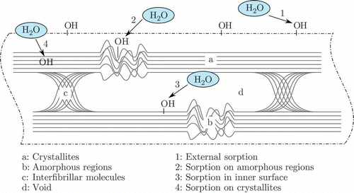
In the molecular structure of cellulosic fibres is shown. Like a polymer, viscose fibres have crystalline and amorphous regions. The sorption on external and amorphous regions is supposed to be the fast mechanism, where the sorption on inner surfaces and crystallites region is the slow mechanism [Citation25]. The process of remoistening the fibres with humid air and the pneumatic transportation pipes can also be modelled by this sorption model.
2.5.4. Overlapping drying phases
Due to moisture inhomogeneity in the fibrous web, it is not suitable to strictly separate the three phases of drying kinetics. Therefore, they are applied into the drying process model with overlapping sections. The second phase starts when the fibre moisture reaches 85%. This is the point when viscose fibres are supposed to have no more moisture on the surface, because they swell due to humidity and can absorb up to 85% water in terms of weight. At approximately 20% fibre moisture, the second phase of drying kinetics begins to fade away and terminates at 10% fibre moisture. While the second phase is fading away linearly, the third phase, the sorption model, becomes more prominent. This is performed due to physical reasons (see above: moisture inhomogeneity) and in order to get a smooth change from the second to the third kinetics model, which is also fitting the measurement data better.
2.6. Experimental modelling
One main advantage of MPC strategy is that measurable disturbances can be implemented directly into the control algorithm. In order to be able to predict a disturbance on the measured fibre moisture, a disturbance model for variation of fibre sheet thickness is added to the prediction model.
This disturbance can be measured a long time before it has effect on the controlled variable, so the controller can act as soon as the model predicts a disturbance on the output. The measured signal has a high noise level, nevertheless, when a real change of the fibrous web occurs, it can be clearly detected by a downward peak, see (model input signal). As a consequence, a model that only considers and recognizes the significant reduction in sheet thickness was needed.
Figure 5. Validation of identified disturbance model. The disturbance is given by a variation in fibre sheet thickness.
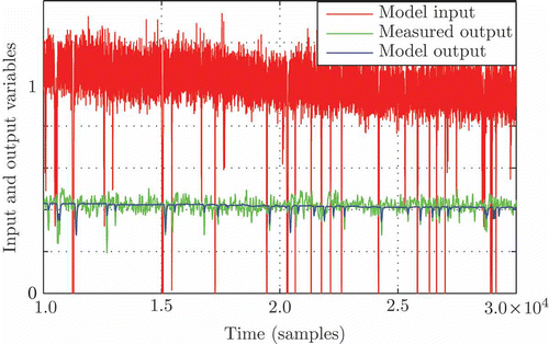
Utilizing measured data in time-domain an identification was realized. The goal was to obtain a transfer function plus the dead time. By realizing a correlation analysis [Citation26], the correct dead time was obtained. With this knowledge an estimation with the output error method was performed. As a result of this a fourth-order discrete-time transfer function model of the disturbance was obtained, which was validated by cross-validation.
As intended, simulation results show that the identified disturbance model gives good results by considering only real disturbances on the sheet thickness, while ignoring the noise on the measured signal. Only the gain had to be adjusted slightly.
In the simulated output of the disturbance model is shown. As quoted before, the disturbance model only takes the peaks of the signal into account. Therefore, model simulation and measured output on fibre moisture have a good accordance, considering moisture drops and correct dead time, while the variance of fibre moisture around the mean value is not simulated by the disturbance model.
Since the effect of the remoistening process on the viscose fibers is not completely clear (see Chapter 4), also in this case a data-based model was identified. The output behaviour of fibre moisture was investigated after a stepwise change of the amount of water remoistening the fibre web. From the data of this step response, the parameters for a PT1 model with dead time, which approximately fits the data curve, were determined.
3. Experimental validation
To perform a validation of the model, it was necessary to make some specific measurements at the real plant. Because there are no online sensors for fibre humidity, samples of fibre flakes were taken from the dryer and their moisture setting was determined gravimetrically. For this reason primarily only a validation of the stationary process has been made, but for different operating points for example, different fibre types with different drying temperature profile. One uncertainty is that the results of the measurements can vary up to 5% in terms of absolute moisture setting.
From the first implementation test of an MPC control strategy additional dynamic data for validation was obtained. The sampling time in the control loop was 6 seconds. So far, the temperatures of the heating zones have been fixed to constant values. The new control strategy also uses this temperatures in the dryer as manipulated variables in order to maintain the controlled variable close to the desired reference value. For this reason, transient behaviour of the dryer temperatures was applied to the process for the first time. Therefore, measured data can now be used for a dynamical validation of the process. Since there exists only one online measurement of fibre moisture after a pneumatic transportation, see , this dynamical validation can only be performed for the simulated output at this location of the process.
4. Results and discussion
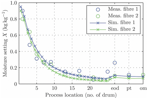
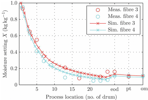
The primary goal was to simulate the longitudinal progression of fibre water content through the dryer, knowing the main influence factors on the process like incoming humidity of fibres and drying air as well as the drying temperature distribution along the dryer. Stationary simulation results generally show good accordance with the measured data. In and some measurement data compared to the simulation results are plotted. In the remoistener the fibre is remoistened by humid air, which means mass transfer via the gas phase. In this case the sorption model calculates a light increase of fibre moisture. However, the measurements of the fibre samples generally show a higher moisture level, which in most cases is physically not reachable [Citation27]. The simulation results indicate the possibility that the fibre setting does not only rise as expected by the mechanism of sorption. One reason for this effect could be that some water in liquid phase goes directly onto the fibres or the flowmeter of the moistener is biased.
Figure 7. Validation with different fibre types at different operation points; the numbers at the axis ‘process location’ are the numbers of the drums, ‘eod’ means ‘end of dryer’ (after the moistener), ‘pt’ means ‘pneumatic transportation’ and ‘om’ stands for ‘online measurement’.
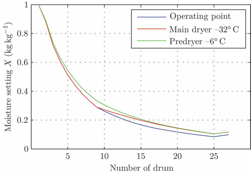
In simulation results for transient procedures for the predryer consisting of 8 drying drums are shown. In the diagram each curve corresponds to the progression of fibre moisture setting over time for one drum. Another result of simulations was a sensitivity analysis how the drying air temperature level has to be reduced in order to obtain 2% higher moisture setting of the fibres at the end of the drying process. The temperature levels in the predryer and the main dryer were considered. The results are as follows: A decrease of the temperature level of 6°C in the predryer (high drying rates) has the same effect on the fibre moisture output like a decrease of the temperature level of 32°C in the main dryer. This signifies that the temperature in the predryer has a much stronger influence on the fibre moisture output than the temperature in the main dryer. In the different progressions of fibre moisture curves that finally end up with the same end value at drum 24 are depicted.
Figure 8. Simulation of transient behaviour; X 0 is the incoming moisture setting of the fibres, X 1 until X 8 is the moisture setting at each drum. At t = 1500 s X 0 takes a step to X 0 = 0.9, at t = 2500 s the fibrous web becomes thinner and at t = 3500 s temperature of drying air decreases by 5°C at every drum. Moisture settings Xi are normalized.
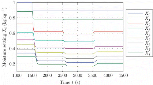
Figure 9. Sensitivity analysis of temperature levels in the dryer; the predryer consists of the drums 1–8, the main dryer of the drums 9–24.
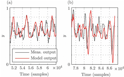
Dynamical validation results are depicted in . After fitting some process parameters, simulated and measured outputs also indicate good accordance between model and the real process. In some occasions the corresponding peaks of model and measurement data are not exactly at the same position. This problem can be explained by a variable dead time. This dead time has a mean value but can vary up to one minute.
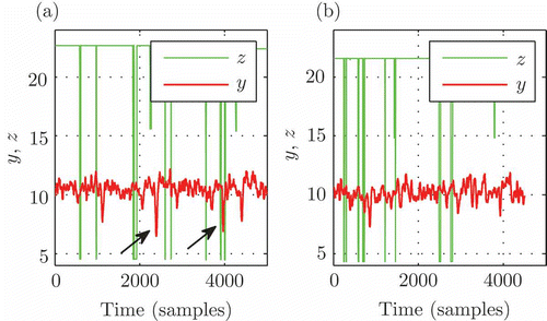
Figure 10. Dynamical Validation: (a) the output signal y with its typical variance is shown; (b) a case with measurable disturbance (fibre sheet thickness) is depicted.
A result of a successful application of the dryer model in an MPC control algorithm [Citation28,Citation29] is shown in , where conventional PID (proportional-integral-differential) and MPC control are compared. It can be noticed that a significant reduction of the water consumption and a much better disturbance rejection can be realized. A robust MPC control can only be obtained with a suitable model and high dynamic accuracy.
Figure 11. Comparison between PID and MPC strategy. u are the manipulated variables (heating power and water), z is a disturbance variable (fibre sheet thickness) and y is the controlled variable.
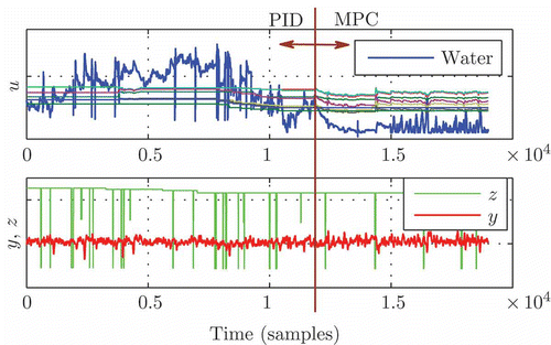
In MPC starts at about sample-time 12,000, well recognizable when all MVs begin to fall. As can be seen, the controlled variable y can be held at the setpoint as before, but with lower energy consumption. This is due to the fact that a setpoint was given to the manipulated variable water with a minimal value. For that reason the water input is tending to get near the setpoint except for compensating a large deviation of y. As a consequence, the temperatures of the heating zones are reduced as well. shows the difference of measured disturbance compensation between PID control and MPC. In (a), especially small negative peaks of the disturbance z cause a high drop of fibre moisture y, designated by arrows; In (b), the MPC strategy manages to compensate disturbances and a suitable control action is achieved.
5. Conclusion
Based on theoretical and practical investigations, a dynamic model of a convective drying process, through-air drying of viscose staple fibres on sieve drums, was presented. Important properties of the drying drum model are its modularity and its scalability. The system is discretized, therefore the model equations are ordinary differential equations. For the air flow through the fibre web a pipe flow is assumed. Drying kinetics are separated into three phases with different mathematical formulations.
Simulation results of transient behaviour of the drying process and a sensitivity analysis of the drying air temperature level in the predryer and the main dryer are shown. Stationary validation at different operating points (different fibres, different temperature levels) of the process model generally shows a good accordance between the model simulation results and measured data.
Experimental disturbance models for sheet thickness and the remoistening process were obtained from time-domain data and added to the physical model of the dryer,thus grey-box modelling was performed. Dynamical validation for the model output using the grey-box model shows a good accordance with measurement data.
The established process model's performance is utilized in an MPC application. Results show its suitability to predict the process output with small prediction errors. For this reason robust and reasonable control action can be obtained from the MPC algorithm.
Nomenclature
| A | = |
Surface of the fibres in one element (m2) |
| b | = |
Width of the fibre belt (m) |
| c | = |
Constant factor (–) |
| cp | = |
Specific heat capacity (J kg−1 K−1) |
| D | = |
Diffusion coefficent (m2s−1) |
| d | = |
Thickness of the fibre web (m) |
| e, f | = |
Exponents [–] |
| h | = |
Specific enthalpy (J kg−1) |
| Δhv | = |
Specific enthalpy of evaporation (J kg−1) |
| l | = |
Overall length of fibre belt (m) |
| l | = |
Characteristic length (m) |
| Le | = |
Lewis number |
| m | = |
Mass (kg) |
|
| = |
Massflow (kg s−1) |
| M | = |
Molar mass (kg mol−1) |
| Mt | = |
Change of mass at time t (%) |
| Minf | = |
Change of mass at equilibrium (%) |
| MPC | = |
Model predictive control |
| Nu | = |
Nusselt number (–) |
| p | = |
Absolute pressure (Pa) |
| pV A | = |
Partial pressure of vapour in air (Pa) |
| pV S | = |
Partial pressure of vapour in boundary layer (Pa) |
| P I D | = |
Proportional integral differential |
| Pr | = |
Prandtl number [–] |
| PT1 | = |
Proportional first-order time delayed |
|
| = |
Massflow (kg s−1) |
| R | = |
Universal gas constant (J mol−1 K−1) |
| Re | = |
Reynolds number [–] |
| s | = |
Length of water free capillary (m) |
| Sc | = |
Schmidt number [–] |
| Sh | = |
Sherwood number [–] |
| t | = |
Time (s) |
| T | = |
Temperature (°C) |
| u | = |
Velocity of flow through the fibre sheet (m s−1) |
| v A,z | = |
Velocity of air flow through the free cross-section area (m s−1) |
| V | = |
Volume of a control element (m3) |
| X | = |
Moisture content (kg kg−1) |
| Y | = |
Humidity of air (kg kg−1) |
| Δy | = |
Length of a discrete fibre web element (m) |
| Greek Letters | = | |
| α | = |
Heat transfer coefficient (Wm−2 K−1) |
| β | = |
Mass transfer coefficient (m s−1) |
| ϵ | = |
Porosity [–] |
| μ | = |
Diffusion resistance coefficient [–] |
| ν | = |
Kinematic viscosity (m2 s−1) |
| λ | = |
Thermal conductivity (W m−1 K−1) |
| ρ | = |
Density (kg m−3) |
| τ | = |
Characteristic time constant (s) |
| Subscripts | = | |
| A | = |
Air |
| F | = |
Fibre |
| i | = |
Element index |
| in | = |
Input |
| S | = |
Surface |
| V | = |
Vapour |
| W | = |
Water |
Acknowledgement
This work was in part financially supported by FFG, project number 815448/13871, by Lenzing AG and by VOIGT+WIPP Engineers GmbH.
References
- Shukla , K.N. 1990 . Diffusion Processes during Drying of Solids , Singapore : World Scientific .
- Mujumdar , A.S. 2006 . Handbook of Industrial Drying , 3rd , Boca Raton , FL : CRC Press .
- Ryan , M. , Modak , A. , Zuo , H. , Ramaswamy , S. and Worry , G. 2003 . Through air drying . Drying Technol. , 21 ( 4 ) : 719 – 734 .
- Ramaswamy , S. , Ryan , M. and Huang , S. 2001 . Through air drying under commercial conditions . Drying Technol. , 19 ( 10 ) : 2577 – 2592 .
- Turner , I. and Mujumdar , A.S. 1996 . Mathematical Modeling and Numerical Techniques in Drying Technology , Boca Raton , FL : CRC Press .
- Incropera , F.P. , DeWitt , D.P. , Bergman , T.L. and Lavine , A.S. 2011 . Fundamentals of Heat and Mass Transfer , 7th , Hoboken , NJ : Wiley .
- Schiesser , W.E. and Silebi , C.A. 1997 . Computational Transport Phenomena: Numerical Methods for the Solution of Transport Problems , Cambridge : Cambridge University Press .
- Weineisen , H. and Stenström , S. 2005 . Modeling through drying of tissue – effect of pore size distribution on drying characteristics . Drying Technol. , 23 ( 9 ) : 1909 – 1923 .
- Ryan , M. , Zhang , J. and Ramaswamy , S. 2007 . Through air drying of tissue and towel under commercial conditions . Drying Technol. , 25 ( 1 ) : 195 – 204 .
- Ghazanfari , A. , Emami , S. , Tabil , L.G. and Panigrahi , S. 2006 . Thin-layer drying of flax fiber: I. Analysis of modeling using Fick's second law of diffusion . Drying Technol. , 24 ( 12 ) : 1631 – 1635 .
- Pang , S. 2000 . Mathematical modelling of MDF fibre drying: Drying optimisation . Drying Technol. , 18 ( 7 ) : 1433 – 1448 .
- Iguaz , A. , Budman , H. and Douglas , P.L. 2002 . Modelling and control of an alfalfa rotary dryer . Drying Technol. , 20 ( 9 ) : 1869 – 1887 .
- Sano , Y. 2001 . Drying behavior of acetate filament in dry spinning . Drying Technol. , 19 ( 7 ) : 1335 – 1359 .
- Metzger , T. , Kwapinska , M. , Peglow , M. , Saage , G. and Tsotsas , E. 2007 . Modern modelling methods in drying . Transp. Porous Media , 66 : 103 – 120 .
- LeVegue , R. 2007 . Finite Difference Methods for Ordinary and Partial Differential Equations: Steady-State and Time-Dependent Problems , Seattle , WA : SIAM .
- Gresho , P.M. and Sani , R.L. 2000 . Incompressible Flow and the Finite Element Method. Volume 1: Advection-Diffusion , Hoboken , NJ : Wiley .
- Ozisik , M.N. 1994 . Finite Difference Methods in Heat Transfer , Boca Raton , FL : CRC Press .
- Courant , R. , Friedrichs , K. and Lewy , H. 1928 . Über die partiellen Differenzengleichungen der mathematischen Physik . Math. Ann. , 100 : 32 – 74 .
- Baehr , H.D. and Stephan , K. 2010 . Wärme- und Stoffübertragung , 7th , Berlin : Springer .
- Gnielinski , V. 1978 . Gleichungen zur Berechnung des Wärme- und Stoffaustausches in durchströmten ruhenden Kugelschüttungen bei mittleren und großen Pecletzahlen . Verfahrenstechnik , 12 ( 6 ) : 363 – 366 .
- Stieß , M. 1995 . Mechanische Verfahrenstechnik 1 , Berlin : Springer .
- Krischer , O. and Kast , W. 1992 . Die wissenschaftlichen Grundlagen der Trocknungstechnik , Berlin : Springer .
- Jaturonglumlert , S. and Kiatsiriroat , T. 2010 . Heat and mass transfer in combined convective and farinfrared drying of fruit leather . J. Food Eng. , 100 : 254 – 260 .
- Sander , A. 2007 . Thin-layer drying of porous materials: Selection of the appropriate mathematical model and relationships between thin-layer models parameters . Chem. Eng. Process. , 46 : 1324 – 1331 .
- Kohler , R. , Alex , R. , Brielmann , R. and Ausperger , B. 2006 . A new kinetic model for water sorption isotherms of cellulosic materials, Macromol . Symp. , 244 ( 1 ) : 89 – 96 .
- Ljung , L. 1999 . System Identification: Theory for the User , 2nd , Upper Saddle River , NJ : Prentice Hall .
- Knoglinger , J. 1996 . Sorptionsisothermen von Lyocell- und Viskosefasern . Lenzinger Ber , 75 : 37 – 40 .
- Schuster , A. and Kozek , M. Constrained Model Predictive Control Implementation in an Industrial Drying Process . Proceedings of the 7th IEEE International Conference on Computational . Palma de Mallorca , , Spain : Cybernetics, IEEE .
- Schuster , A. , Kozek , M. , Voglauer , B. and Voigt , A. Constrained Model Predictive Control of an Industrial Drying Process for Viscose Staple Fibres . Proceedings of the 2010 ASME Dynamic Systems and Control Conference . Cambridge , MA : ASME .
