Abstract
This article presents a new generalized non-linear dynamical model of a transformer with saturation and hysteresis effects. The structure of this new model is based on a magnetic equivalent circuit with non-linear reluctance elements. Using this method, accurate models of three- and five-legged transformers with magnetic saturation and hysteresis phenomena of iron core are introduced and inrush current in normal and sequential phase energization techniques are evaluated. Moreover, the effects of neutral resistance, magnetic structure and winding connections on inrush current are determined. In addition, for validation of the proposed model, some numerical simulations are made and compared with other techniques. Simulation results illustrate that the proposed model has high accuracy and efficiency for non-linear dynamical modelling of a transformer.
1. Introduction
Ferromagnetic materials are a major component of electromagnetic equipment in power systems that have non-linear characteristics such as core saturation and hysteresis loops. Structures of magnetic and electric circuits in these types of equipment cause different parts of the magnetic core to operate at different points of the B(H), thus, a full non-linear dynamical model of such a system becomes too complicated [Citation1]. In these cases, the non-linear dynamical model of a system based on non-linear inductances are not validated.
However, power transformers are one of the most important and common magnetic devices in power systems. According to magnetic and electric circuits, different models have been developed for analysis of transformers with saturation and hysteresis loss. In Reference [Citation2], using a magnetic equivalent circuit, a geometrical model for linear transformers was developed and sequence inductance matrices of the system were determined. In addition, saturation and hysteresis characteristics of individual magnetic circuit branches can be approximated by B-spline curve fitting techniques [Citation3]. In this method, reluctance of magnetic paths in a transformer depends on flux paths. Consequently, the flux linkage in a transformer system cannot be separately determined in a non-linear condition. In [Citation4], a PSpice model of a three-phase transformer with three legs has been developed using a magnetic equivalent circuit and three constant resistances in parallel with the induced primary voltages illustrating total core losses in the transformer. Although the proposed model is simple and reliable, it cannot consider the saturation and loss of different parts of a magnetic core, individually. Moreover, transient analysis softwares such as the Alternative Transients Program (ATP) and ElectroMagnetic Transient Program (EMTP) have not determined an exact model of a transformer with linkage flux among different phases [Citation5].
Recently, a dynamic model of hysteresis loops with non-linear magnetization characteristics has been developed for the prediction of iron loss in ferromagnetic materials [Citation6]. In small signal applications, a circuit model of a magnetic core with non-linearity, hysteresis and eddy currents were presented [Citation7]. In power applications, a dynamic hysteresis method [Citation8] has often been used for the hysteresis loop in a non-linear magnetic core. These methods have higher accuracy but lower computing speed in comparison to other methods and require specific accurate characteristics of the magnetic material.
In this article, using connection matrices in magnetic and electric circuits, a systematic method is introduced to determine the magnetic and electrical models of transformers with saturation and hysteresis effects. In this method, the hysteresis loss for each magnetic path of a transformer is individually included by a fictional coil. In addition, a non-linear reluctance, which is dependent on the flux path, is used for considering the saturation effect of a magnetic path in a system. Furthermore, accurate models of transformers with three and five legs are developed and effects of neutral resistance in reduction of inrush current in the sequential phase energizing technique are evaluated [Citation9,Citation10]. Simulation results show that the generalized non-linear dynamical model has high accuracy and efficiency for analysis of the non-linear phenomena in electromagnetic system.
The outline of this article is as follows: in Section 2, we introduce a Fundamental Magnetic Path (FMP) and utilize it to determine electrical equations of an electromagnetic system. In Section 3, we describe Amper's law to obtain a non-linear algebraical–differential equation in the system. In Section 4, the proposed method is applied to three- and five-legged transformers. In Sections 5 and 6, some simulations results, comparing and concluding remarks are given. Finally, a summary of main symbols is given in Table A1 in the Appendix.
2. Electrical model of electromagnetic systems
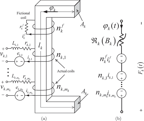
Magnetic structure of an electromagnetic device is formed by several magnetic paths where the saturation and loss of the magnetic core depend on the density of flux, (B – H) characteristic and source frequency. The magnetic topology can be divided into some magnetic tubes with constant flux density, thus an FMP, which is shown in (a), is used for modelling a magnetic circuit with constants of cross area (Ak
), length (lk
) and magnetic permeability of a material . In this figure, FMP is excited with mk
by separated coils, where nk,j
, Lk,j
and rk,j
denote turn, leakage inductance and series resistance, respectively, of the kth FMP in the jth coil. In addition, ϕ
k
(t) and Bk
(t) are magnetic flux and density of the kth FMP, simultaneously. Moreover, (b) shows the magnetic equivalent circuit of the FMP considering non-linear magnetic reluctance and magnetomotive force (MMF) in ampere-turns.
Figure 1. Magnetic structure and equivalent circuit of the FMP. (a) Fundamental path and (b) magnetic equivalent circuit.
The flux density of the kth FMP (Bk
(t)) can be expressed in the -order of Fourier series as
If a magnetic circuit can be formed by number of n FMPs, the number of total actual coils (m) in an electromagnetic system will be equal to
In (a), voltage equations of the actual coils at the kth FMP (without fictional coil) in vector form can be written as
The sign of nk,i
for right(left)-oriented coil is assumed positive (negative). Core loss of the kth FMP can be introduced by a fictional coil with turns where the voltage equation for this coil can be written as
Using EquationEquations (5)(5) and Equation(7)
(7), inductance, resistance and turn matrices in EquationEquation (9)
(9) can be obtained as
Similarly, the voltage relations of the fictional coils in EquationEquation (8)(8) can be augmented as
Using EquationEquation (8)(8), resistance and turn matrices in EquationEquation (12)
(12) can be obtained by
Because coil currents depend on the excitation voltages and circuit connections, we consider m main coils in the system that are connected in the p meshes. Using the connection matrix C v, we can write the Kirchhoff's Voltage Law (KVL) equations for the m meshes in the system. For this purpose, the matrix relation between the current vector of the actual coils ( i s (t)) with the vector of mesh currents ( i m (t)) can be written as
The (jth, kth) element of the matrix C
v is 1 when the jth coil of the system is connected to the kth mesh current in the same reference direction, is –1 for opposite reference direction and is otherwise 0. By multiplying EquationEquation (9)(9) by C
v in the left-hand side and combining it with EquationEquations (15)
(15) and Equation(17)
(17), the electrical voltage relations of a magnetic system can be expressed as
In some conditions, the actual coils in a system may be connected by external impedances without any dependence on a system's fluxes. For example, the star connection of three primary coils in a three-phase transformer with neutral impedance (rn
) is a case in that the neutral impedance is connected to three-phase primary coils (). In this case, the three-phase primary coils depend on FMP fluxes; however, the neutral impedance does not depend on any FMP fluxes. In these conditions, turn number of the external impedance in EquationEquation (18)(18) is set to zero.
For determining currents of actual coils (
i
m (t)) in EquationEquation (18)(18), we need to obtain a relation between electrical currents (
i
m (t)) and magnetic fluxes ψs (t). In the next section, non-linear algebraic relations are introduced using a magnetic circuit as shown in (b).
3. MMF in magnetic circuit
By applying Ampere's law to the kth FMP in (b), we can write
The non-linear (B – H) curve and hysteresis loop in magnetic paths are introduced by variable reluctances in EquationEquation (23)(23) and fictional coil currents in EquationEquation (12)
(12), which are dependent on magnetic flux. Tangent, exponential, polynomial and piecewise linear functions have been proposed to approximate the B – H curve [Citation12,Citation13]. In this article, the permeability of the FMP is given as
Figure 2. B – H and μ r (H) characteristics of the Armco M5 Steel [Citation14].
![Figure 2. B – H and μ r (H) characteristics of the Armco M5 Steel [Citation14].](/cms/asset/d75aaf24-5729-489a-b703-8414955bf4df/nmcm_a_695740_o_f0002g.jpg)
According to the FMP connection in the magnetic circuit and using the continuity of flux with Ampere's law, a relation between the magnetic flux vector of the FMP (ψs (t)) and the mesh flux of the magnetic circuit (ψm (t)) can be expressed as
Substituting EquationEquation (27)(27) in EquationEquations (12)
(12) and Equation(18)
(18) and using EquationEquation (29)
(29), we can obtain a generalized and augmented model of an electromagnetic system as
This matrix relation presents non-linear singular differential equations with p + q + n unknown variables (
i
m (t),
m (t) and
i
f (t)). Table A1 provides an overview and a succinct definition of all important quantities used in the model. Due to a non-linear magnetic characteristic, the non-linear algebraical–differential equations in (31) have to be solved simultaneously. In the following section, this model is applied to transformers with three and five legs for transient analysis of non-linear conditions, such as inrush current phenomena in the energizing process.
4. Non-linear model of transformers with three and five legs
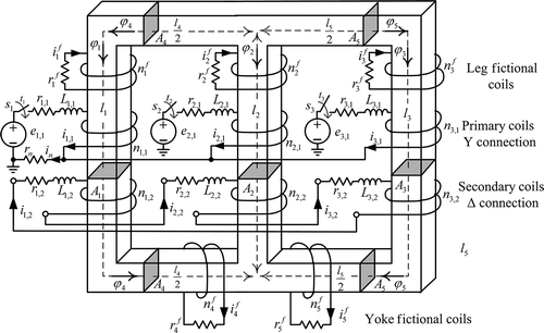
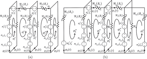
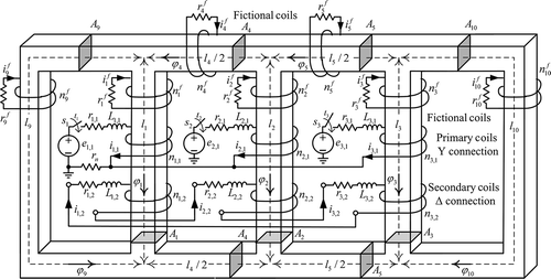
Magnetic structure and electric connection of transformers with three and five legs are shown in and . The magnetic circuit of the three-legged transformer consists of five non-linear cores with non-linear reluctances ( to
). Three linear reluctances (
to
) are provided to present air gap fluxes for each leg, individually. In asymmetrical exciting, coil currents and fluxes of core paths can vary independently. In these conditions, a non-linear dynamic model of a transformer based on flux, current and core losses is necessary. shows the magnetic equivalent circuit for and . In these circuits, linear reluctances
,
and
illustrate the air path for each internal leg. In addition, in and , the primary and secondary actual coils are connected in star with neutral resistance rn
and delta configurations, respectively.
The worst-case condition for analysis of the inrush current of a transformer is a no-load situation. Thus, in this condition, and
are secondary currents for Y/Δ and Y/Y connections, respectively. Based on and , we can write three (p = 3) and four meshes (p = 4) for Y/Y and Y/Δ connections, respectively. Similarly, using , the independent mesh fluxes
to
, for a magnetic circuit can be written. Numbers of independent variables for a magnetic circuit are q = 5 for three and q = 7 for five leg configurations. In addition, n and m for transformers with three and five legs are 9 and 12 and 11 and 14, respectively. Thus with attention to and (a), the system variables in EquationEquation (31)
(31) for the three-legged transformer are chosen as
Due to the reluctance of the ,
and
as linear and without any losses, we ignore
,
and
in
i
f (t). In addition, using EquationEquations (17)
(17) and Equation(27)
(27), connection matrices C
v and C
M can be obtained as
In addition, using EquationEquations (19)(19), (30), (34) and (35), mesh resistance, inductance and reluctance matrices in EquationEquation (31)
(31) can be written as
The relations (31)–(41) present non-linear algebraical–differential models of a three-legged transformer in that unknown variables are completely coupled together. Similarly, we can obtain a non-linear algebraical–differential model for a five-legged configuration with non-linearity and hysteresis phenomena. Some simulation results can be obtained using advance numerical methods for transient analysis of asymmetrical conditions. Decreasing the inrush current of transformers by a sequential phase energization method is an interesting case in an asymmetrical condition [Citation9,Citation10]. In this case, the transient inrush current in a three-phase transformer will decrease energizing when the primary coils energize sequentially. By sequential phased energization of each coil, the neutral resistor can be connected as a series with an excited coil; thus, the transient inrush current is significantly reduced. In the next section, the performance and characteristics of this method for three- and five-legged transformers are evaluated.
5. Simulation results
For evaluation of two types of three-phase transformers, three switches shown in and are simultaneously closed and the three primary coils of the transformers are energized by three-phase sinusoidal voltage. The geometrical and electrical parameters of two transformers are introduced in and [Citation13,Citation15].
Table 1. Dimensions of transformers.
Table 2. Electrical parameters of the transformers with three and five legs [Citation13].
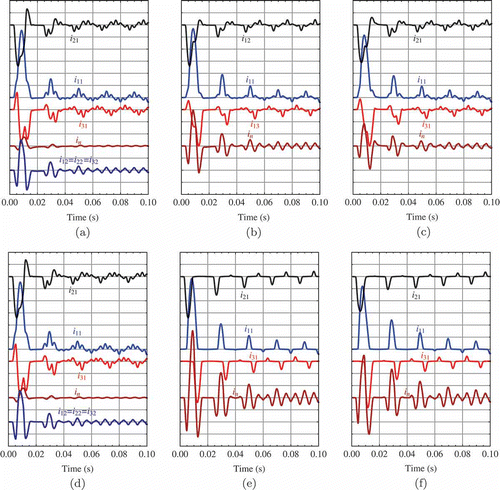
Primary and secondary currents of the transformer with three legs are shown in some different configurations ((a)–(c)). The maximum transient current is obtained by Y/Y connection with rn = 0. For validation of the proposed model with other techniques, the comparison of experimental and simulation results of the maximum magnitude of currents in Y/Y connection with rn = 0 are shown in . Similar simulation results for a transformer with five legs are illustrated in (d)–(f). By comparing , transient inrush currents in transformers with five legs are slightly higher than other in winding connections.
Table 3. Maximum inrush currents for three legs, Y/Y, r n = 0.
Figure 6. Inrush currents of the three- and five-legged transformers, scale: . (a) Three legs, Y/Δ, rn
= 0; (b) three legs, Y/Y, rn
= 0; (c) three legs, Y/Y, rn
= 2.5Ω; (d) five legs, Y/Δ, rn
= 0; (e) five legs, Y/Y, rn
= 0; and (f) five legs, Y/Y, rn
= 2.5Ω.
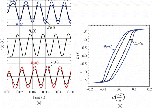
In addition, the maximum current in a coil coincides with the flux saturation in its magnetic path. This phenomenon for (c) is shown in (a). Due to the cross area of the yoke being higher from leg in this transformer, contrary to leg paths operated in the saturation zone, the yoke paths are in the linear region. (b) shows the dynamic hysteresis loops in these cases. Because of transient characteristics of inrush currents, the hysteresis loops are asymmetric. Moreover, areas of the hysteresis loops for each leg are higher than those of yoke paths.
Figure 7. Flux and hysteresis in a three-leg Y/Y transformer with rn = 2.5Ω. (a) Flux density, scale: 1 T/div. and (b) hysteresis loops.
The phase sequential energization method was introduced for limiting magnitude of an inrush current [Citation9,Citation10]. For evaluating the ability of this method, the phase sequential energization technique in two types of transformers is implemented. Three switches (s 1, s 2 and s 3) in two types of transformers are sequentially closed. First, s 1 is closed and after reaching i 1,1 (t) to a steady condition, s 2 is closed. This sequential operation is continued for s 3. shows the three-phase currents when the sequential switching is applied to transformers. The results show that the phase sequential energization method in the three-legged transformer can effectively reduce the maximum magnitude inrush current. The maximum amplitude of the inrush currents for these transformers is included in . By comparing results in this table, we can find out the maximum magnitude ratio of a phase current in a phase sequential to simultaneous energization methods. The table shows reductions of about 75% for ia and 15% for ib and ic .
Table 4. Maximum inrush currents for different types of transformer.
Figure 8. Inrush currents in the sequential phase energization method with rn
= 2.5Ω, scale: . (a) Five legs, Y/Δ, (b) three legs, Y/Y and (c) five legs, Y/Y.
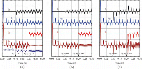
These results show that the proposed method can be used to analyse complex structures of magnetic and electrical circuits with different hysteresis and saturation characteristics, separately.
6. Conclusion
In this article, a generalized non-linear dynamical model of electromagnetic systems with saturation and hysteresis effects was presented. Based on the electric and magnetic connection matrices, the magnetic and electrical relations of transformers were introduced and an algebraic and a dynamic model of the system was presented. This model was very effective for modelling and analysing of asymmetric non-linear conditions such as inrush current and hysteresis phenomena in a power transformer. Finally, this model was applied to both three- and five-legged transformers, and it was demonstrated that a sequential phase energization technique in a transformer is a suitable method for reduction of maximum magnitude of inrush current.
References
- Cho , S.D. 2002 . Parameter estimation for transformer modeling , Ph.D. thesis, Michigan Technological University .
- Hatziargyriou , N.D. , Prosalidis , J.M. and Papadias , B.C. 1993 . Generalized transformer model based on the analysis of its magnetic core circuit . Gener. Transm. Distrib. IEE Proc. C , 140 : 269 – 278 .
- Dolinar , D. , Pihler , J. and Grcar , B. 1993 . Dynamic model of a three-phase power transformer . IEEE Trans. Power Deliv , 8 : 1811 – 1819 .
- Pedra , J. , Sainz , L. , Crcoles , F. , Lopez , R. and Salichs , M. 2004 . PSPICE computer model of a nonlinear three-phase three-legged transformer . IEEE Trans. Power Deliv , 19 : 200 – 207 .
- Chen , X. 1996 . A three-phase multi-legged transformer model in ATP using the directly-formd inverse inductance matrix . IEEE Trans. Power Deliv , 11 : 1554 – 1562 .
- Kucuk , I. and Derebasi , N. 2006 . Dynamic hysteresis modelling for toroidal cores . Physica B , 372 : 260 – 264 .
- Gruosso , G. and Brambilla , A. 2008 . Magnetic core model for circuit simulations including losses and hysteresis . Int. J. Numer. Model. Electron. Networks Devices Fields , 21 : 309 – 343 .
- Moses , P.S. , Masoum , M.A. and Toliyat , H.A. 2010 . Dynamic modeling of three-phase asymmetric power transformers with magnetic hysteresis: no-Load and inrush conditions . IEEE Trans. Energy Convers , 25 : 1040 – 1047 .
- Xu , W. , Abdulsalam , S.G. , Cui , Y. and Liu , X. 2005 . A sequential phase energization technique for transformer inrush current reduction part II: theoretical analysis and design guide . IEEE Trans. Power Deliv , 20 : 950 – 957 .
- Xu , W. , Abdulsalam , S.G. , Cui , Y. and Liu , X. 2007 . A sequential phase energization method for transformer inrush current reduction-transient performance and practical considerations . IEEE Trans. Power Deliv , 22 : 208 – 216 .
- Ray , S. 1991 . Analysis of transient behaviour of power system circuits containing iron cored coils . IEE Proc. C , 138 : 275 – 282 .
- J. Nazarzadeh and V. Naeini, Magnetic Reluctance Method for Dynamical Modeling of Squirrel Cage Induction Machines, M. Chomat, ed., InTech, Croatia, 2011, pp. 41–60, available at http://www.intechweb.org/ (http://www.intechweb.org/)
- Elleuch , M. and Poloujadoff , M. 1996 . A contribution to the modeling of three phase transformers using reluctances . IEEE Trans. Magn , 32 : 335 – 343 .
- Hernandez , I. , Olivares-Galvan , J.C. , Georgilakis , P.S. and Canedo , J.M. 2010 . A novel octagonal wound core for distribution transformers validated by electromagnetic field analysis and comparison with conventional wound core . IEEE Trans. Magn , 46 : 1251 – 1258 .
- Cui , Y. , Abdulsalam , S.G. , Chen , S. and Xu , W. 2005 . A sequential phase energization method for transformer inrush current reduction part I: simulation and experimental Results . IEEE Trans. Power Deliv , 20 : 943 – 949 .
7. Appendix
A list of the main symbols is presented in the following table.
