 ?Mathematical formulae have been encoded as MathML and are displayed in this HTML version using MathJax in order to improve their display. Uncheck the box to turn MathJax off. This feature requires Javascript. Click on a formula to zoom.
Abstract
The approach presented in this paper yields a reduced order solution to the universal Reynolds equation for incompressible fluids, which is valid in lubrication as well as in cavitation regions, applied to oil-film lubricated journal bearings in internal combustion engines. The extent of cavitation region poses a free boundary condition to the problem and is determined by an iterative spatial evaluation of a superposed modal solution. Using a Condensed Galerkin and Petrov–Galerkin method, the number of degrees of freedom of the original grid is reduced to obtain a fast but still accurate short-term prediction of the solution. Based on the assumption that a detailed solution of a previous combustion cycle is available, a basis and an optimal test space for the Galerkin method is generated. The resulting reduced order model is efficiently exploited in a time-saving evaluation of the Jacobian matrix describing the elastohydrodynamic coupling in a multi-body dynamics simulation using flexible components. Finally, numerical results are presented for a single crankshaft main bearing of typical dimensions.
1. Introduction
Pressure-oiled journal bearings are an essential machine part in various fields of engineering. The mathematical description of hydrodynamic pressure build-up in the oil film dates back to the end of nineteenth century when Osborne Reynolds derived the differential equation named after him [Citation1]. It still remains valid and forms the basis of reams of bearing models proposed during the last century. For a detailed compilation, reference may be made to the relevant literature and only common ones are covered herein.
Basically, when journal bearing lubrication is considered, the oil pressure is determined from clearance gap height, relative sliding speed and oil properties. On the other hand, clearance gap height is a result of the equilibrium condition between journal and shell, which is also influenced by contact forces resulting from the oil pressure. Thus, a highly nonlinear coupling exists and iterative procedures are applied to find an overall equilibrium (e.g. [Citation2,Citation3] and references therein).
Analytical solutions to Reynolds equation can be found using long or short bearing theory. For geometries with very short axial extension, overall oil flow is dominated by the Poiseuille flow component in axial direction, whereas its circumferential component is neglected. The resulting analytical solution is called Ocvirk or short bearing solution [Citation4].
In the Sommerfeld solution for infinitely long bearing geometries [Citation5], the pressure gradient in axial direction disappears and axial flow is neglected.
Another class of solution methods is based on characteristic diagrams. Booker [Citation6] first proposed the mobility method of solution for dynamically loaded bearings. It allows for rapid calculation of the journal orbit, pressure field or required oil flow, but is restricted to rigid shells and simple geometry, e.g. circumferential symmetry.
The most accurate and versatile type of solution for an elastohydrodynamic (EHD) evaluation poses a multi-body dynamic (MBD) simulation using flexible components in conjunction with EHD coupling [Citation2]. A detailed simulation of EHD lubrication leading to fluid–structure interaction can be achieved even for intricate geometries containing various oil grooves or variable boundary conditions, which mainly result from the spatial movement of oil supply features, such as a lubrication bore located on the rotating crank shaft, for example.
In addition to these boundary conditions, there are also free boundary conditions in the description of the occurrence of cavitation in the oil film by cavitation models. As opposed to the analytic approaches, which assume a prescribed cavitation boundary, the extent of cavitation region poses a free boundary condition in a detailed EHD simulation. Thus, regardless of the actual solution approach, an iterative determination of the solution is required.
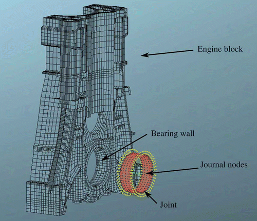
Subsequently, Galerkin method is used in the model order reduction by projection as the periodic nature of combustion engine operation gives rise to new approaches for the generation of projection space and test space. The solution is composed of a modal superposition resulting from the reduced order model. It is spatially evaluated and cavitation boundaries are determined accordingly. These updated boundary conditions are reapplied to the reduced order approach. In addition, the application of the model to the approximation of the Jacobian matrix describing the EHD coupling in a MBD simulation using flexible components is derived and its accuracy is demonstrated. The geometric set-up, which has been used in this paper, is shown in and will be explained in detail in Section 5.
As covered in detail in the next section, Elrod–Adams’ universal cavitation algorithm is used in this paper [Citation7,Citation8]. An effective density as a second independent variable is introduced besides the pressure, treating cavitation as free boundary condition to Reynolds equation. It then poses a switching-type partial differential equation.
Various commercial MBD tools, such as, for example, AVL EXCITE [3], implement the approaches just mentioned to perform vibration or stress analysis for internal combustion (IC) engines. Steady state investigations of specific operating points (e.g. 3000 rpm under full load in time domain) are common. Such sophisticated simulations are evaluated at the expense of a very time-consuming calculation.
To overcome this drawback, the approach presented in this paper takes advantage of its application to the main bearings of an IC engine. In the framework of a detailed MBD simulation using EHD coupling, the first of multiple combustion cycles (720° crank angle in case of a four-stroke engine) is simulated with full degrees of freedom (DOF). Since a steady state operating point is investigated, the assumption that patterns in the oil film as well as the shape of cavitation region reappear periodically is made. By using the information gathered during the first cycle, the reduced order model is readily available without much additional effort. Therefore, an anticipation of the solution at a certain crank angle in successive cycles can already be attained.
The procedure described exploits periodicity in form of a detailed result of the reference combustion cycle in two ways: first in Section 3.1.1 for the generation of projection basis used in the Galerkin method and second in the choice of an optimal test space for the Petrov–Galerkin method in Section 4.3.
It is obvious that a reduced order model and the reduction of DOF cannot provide a solution with the same level of details as a simulation on the full grid. It should be mentioned that the approach presented in this paper mainly aims at a short-term prediction of pressure and fill ratio over a few degrees of crank angle only and not at a fully autonomous simulation over a whole combustion cycle.
Nevertheless, a cut down on calculation time can be achieved allowing for efficient application of the approximation in the overall MBD simulation. Its convergence properties can be improved by a more frequent recalculation of the contact Jacobian, which is time consuming in general. To introduce the reduced order model, the Jacobian matrix, which per definition quantifies a contact force change per body force variation, is split into two multiplicative parts. One comprises the compliance of the flexible components and the second specifies oil pressure change, respectively, contact force change per gap height variation. Herein only the approximation of the pressure field is sufficient. Details on this approach are given in Section 4.5 and a first result in Section 5.
In Section 2, the cavitation model as well as the model for rough sliding surfaces are quickly reviewed. Section 3 gives an overview of model order reduction, Galerkin method in general and the generation of ansatz space used in this paper. Three different solution procedures are described in Section 4 and results are given in Section 5.
2. Reynolds equation
The pressure field in the incompressible oil film of a slider bearing is governed by a two-dimensional second-order partial differential equation. This relation is called Reynolds equation. For a Newtonian fluid, it is derived from the Navier–Stokes equations in combination with the mass continuity condition (for details cf. [Citation9]).
In Reynolds equation, the thickness of fluid film is assumed small compared to the radius of curvature of the bodies in contact. This allows for the examination on a two-dimensional cartesian coordinate system and conversion from cylindrical coordinates is straightforward. Time is denoted by t and spatial coordinates by . The direction of relative surface movement corresponds to x, which is equivalent to the circumferential direction in a bearing and is usually quantified in degree shell angle. The axial coordinate is denoted by y. A typical geometry for main bearings will be covered in Section 5.
For any arbitrary given distribution of the clearance gap height , dynamic viscosity of the oil
as well as its density
and mean relative sliding speed
, the pressure field
can be determined by Reynolds equation using Dirichlet boundary conditions:
Since Reynolds Equation (1) only holds in fully lubricated regions completely filled with oil, the propagation of cavitation can be prescribed in commonly used boundary conditions such as the Sommerfeld, Gümbel or Reynolds condition.
Elrod and Adams [Citation7,Citation8] proposed the Elrod–Adams cavitation model, which is regarded as a reference model in tribology. A saturation function – subsequently called ‘fill ratio’ – is introduced to describe the local ratio of the liquid phase. For incompressible fluids,
equals one in lubrication region, representing a gap completely filled with oil. In cavitation regions, the pressure
is assumed at a constant cavitation pressure
. Only shear and squeeze flow exist to fulfil mass continuity and the solution has to be found with respect to
, which takes values between zero and one. As the extent of cavitation region is not known a priori and changes with the solution, it poses a free boundary condition. Therefore, an iterative evaluation becomes necessary.
The evaluation of slider bearing used herein considers rough sliding surfaces according to the average flow model proposed by Patir and Cheng [Citation10,Citation11]. Pressure flow factors and
as well as a shear flow factor
describe the influence of sliding surface orientation and mean roughness
on the pressure and fill ratio field. Found by numerical flow simulation on a mockup bearing model, these flow factors are expressed as empirical relations in terms of a normalized clearance gap height
and a factor describing surface characteristics [Citation10,Citation11]. They consider that for small clearance gap heights (i.e. high ratios of clearance gap to the mean roughness), the flow is highly influenced by surface roughness, its orientation or even more a micro-textured surface.
Extending (1) by these models leads to the universal averaged Reynolds equation, which holds in full film lubrication as well as in cavitation regions:
In lubrication regions, is equal to one and (2a) solved for p, whereas in cavitation region, p is set to the cavitation pressure
and
becomes the independent variable.
3. Model order reduction
A well-known method for approximating the solution of partial differential equations is Galerkin’s method. Consider the general differential equation
This is equivalent to the requirement that the residuals, which arise from the projection of the original equation onto the ansatz space, weighted by the test space, become zero. Therefore Galerkin’s method is also called method of weighted residuals. For the ansatz space being equal to the test space – the procedure is sometimes referred to as Bubnov–Galerkin method – this amounts to minimizing the squared sum of residuals. For differing spaces, it is called Petrov–Galerkin method.
3.1. Techniques for ansatz space determination
In order to reduce the number of DOF, a projection of the infinite dimensional function space of Reynolds equation onto an ansatz space of lower dimension is performed. General spatial coordinates now become the cartesian coordinates
. Representation of pressure
and fill ratio
as linear combination of m respectively l arbitrary basis-vectors
and
introduces a residual
and
. Modal pressure is denoted by
and modal fill ratio by
:
Prior to performing model order reduction, a spatial discretization using an equidistant rectangular grid with n nodes is applied to (2). A quantity describing field values such as, for example, the pressure is now represented by a vector
containing one row for each node. The projection (3) can be written as
Indices in the notation of ansatz spaces and
indicate their dimensions, that is, for the pressure
.
3.1.1. Choice of ansatz space
Although the selection of ansatz space is arbitrary in general, an appropriate choice should be made to obtain good results with little DOF. Ansatz functions resembling the most common shapes of the solution efficiently lead to a result, which can be represented by a smaller number of them. From a numerical point of view, the best choice is an orthogonal basis. For example, the use of eigenmodes is well established in linear structural dynamics. As an analytic choice for Reynolds equation, Thomas [Citation12] proposes a combination of Fourier series in circumferential direction and Legendre polynomials in axial direction for the pressure field.
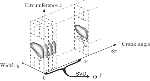
As mentioned in Section 1, the assumption that patterns in the oil film as well as the shape of cavitation region reappear periodically is made. In combination with an existing detailed solution for pressure and fill ratio of the reference combustion cycle, the ansatz space can be generated in an advantageous way by using principal components. This idea is depicted in
The full pressure solution at N points in time is collected into a matrix . For example, if the reference cycle is simulated with the time step size being equal to one degree crank angle rotation,
will contain 720 solution snapshots.
Applying singular value decomposition (SVD) to yields a diagonal matrix
containing the singular values of
and a matrix
. Its columns represent the left singular vectors of
:
The first m singular vectors in affiliated with the biggest singular values are chosen as orthonormal basis of the ansatz space
. As the equation for the fill ratio only differs in its notation, the same procedure applies to the generation of ansatz space of the fill ratio.
Evaluation of Reynolds equation transforms from a node-by-node examination of the independent variable to the weighted linear combination of principal modes of solution. The basis vectors are equivalent to those eigenvectors, which represent the optimal basis defined in the Karhunen–Loéve transform, also called Proper Orthogonal Decomposition (POD), frequently used in fluid dynamics. In an implementation where , the use of POD would lead to exactly the same ansatz functions, but with increased numerical efficiency [Citation13].
3.2. Modal representation and boundary conditions
Substituting the modal representation of pressure and fill ratio (4) in the discretized form of Reynolds Equation (2) yields one of two equations for every node, either for cavitation or lubrication region.
In lubrication region, the substitution of pressure in (2a) evaluated at node i, leads to
The expression denotes the ith line of a matrix containing the spatial derivative of the ansatz functions with respect to x. Depending on their choice, derivatives are found by difference quotient or as analytic derivatives directly.
Since pressure remains constant in cavitation regions, the left hand side of (2a) becomes zero in this case. Applying the product rule and replacing the temporal derivative with the backward difference quotient
[Citation14] denoting discrete points in time
and time step size
, the modal form of Reynolds equation can be written as
Again, the expression denotes the ith line of a matrix containing the spatial derivative of the ansatz functions.
Depending on the location of a node, its corresponding Equation (6) or (7) is added as a row to (8a) or (8b):
Thus, matrices X and V, vectors y and w contain input quantities, their spatial and temporal derivatives as well as that of the ansatz space. Its rows are described by Equations (6) and (7).
Although (8a) and (8b) seem to be independent of each other on the first sight, they are indirectly coupled as they both depend on the extent of the cavitation region as boundary condition. Besides a Dirichlet boundary condition prescribing pressure and fill ratio on the boundary of the domain, an additional condition must be adhered to. For each node lying in the lubrication region, a row is added to (8a) representing the Reynolds equation. At this node, the fill ratio is required to remain one, resulting in a ‘complementary’ condition. A comparable condition applies to the pressure in cavitation region.
All these boundary and complementary conditions are written in matrix form as well. They are contained in the matrices and
, whereas the fixed pressure values on the right hand side are denoted by
. Fill ratio values are set to one at the boundary, which is indicated by the vector
. The complete set of
equations under consideration reads
4. Solution procedures
To solve the actually difficult model order reduction procedure with free boundary conditions, an iteration is performed using a spatial evaluation of a superposed modal solution. The projection of the original Equation (2) onto the ansatz space using a reduced number of modes leads to the overdetermined system of Equations (9a) and (9b). Spatial node-by-node representation of both independent variables has been transformed into a modal representation without any spatial information left. Independently applying one of the proposed solution procedures to pressure and fill ratio yields their corresponding modal coordinates. By means of the ansatz functions, the spatial form of pressure and fill ratio solution is recovered afterwards. Based on this information, the cavitation boundary is evaluated and the algorithm advances to the next iteration step.
Galerkin method requires the residual to be orthogonal to a chosen test space. This Galerkin orthogonality condition poses the essential property of the method. To find a solution for the modal coordinates, the orthogonality condition is applied to each of the two residuals as they are defined in Equations (9a) and (9b).
For simplicity, the derivation of the following solutions is shown for pressure equations only, as the equivalent procedure with comparable notation applies to the fill ratio.
4.1. Flat Galerkin method
By choosing the test space being equal to the ansatz space and using only the first of m available columns of
and
such that all
higher modes are neglected, the Flat Galerkin method is obtained:
Application to the Reynolds Equation (9) yields the solution for the modal pressure
In Equation (11), the boundary conditions are equally weighted as nodes lying within the domain. To emphasize or weaken the influence on the solution of some nodes individually, a diagonal weighting matrix could be introduced. By doing so, the residua are weighted according to the entries of
in advance of the projection onto the test space. A special choice of weighting is made in the following approach.
4.2. Condensed Galerkin method
In the theory of dynamical systems, the Nonlinear Galerkin method is strongly connected to centre and inertial manifolds [Citation15]. Basically, the behaviour of a system is reduced using a projection of higher order dynamics onto a sub-manifold of the phase space, which represents the essential dynamics of the system. The existence of an inertial manifold cannot be proved a priori. Only the assumption is made, that it does exist and an approximate inertial manifold (AIM) can be found by various methods (for an example and references see e.g. [Citation16]).
Concerning the independent variables, the Reynolds equation contains a temporal derivative of the fill ratio on the right hand side of (2a). This term is different from zero, only when a change of fill ratio occurs. As this is mainly the case, when cavitation regions develop or lubrication is reestablished, domains, which are influenced by this term, remain very limited. Therefore, in the time discretized version is represented by a backward difference quotient [Citation14]. The temporal derivative of the gap height can be considered as a given input or can alternatively also be found by backward differences. Basically, the concept of an AIM transforms to static condensation. Although it is based on the same basic concept as Nonlinear Galerkin for nonlinear equations, the approach is denoted Condensed Galerkin in this application.
The solution can be found by splitting the ansatz space into two subspaces
and
. Corresponding modal coordinates are denoted by
and
for higher order modes. Combination of Galerkin orthogonality condition (10) and Reynolds Equation (9) leads to
The relation representing condensed modes can be found by collecting in the second row of (12)
Substituting higher order modes (13) in the first row of (12) yields
Compared to the flat procedure result (11), Condensed Galerkin introduces a variable weighting matrix , which depends on the neglected modes. Since it also contains inputs of the current point in time, it has to be updated online.
4.3. Petrov–Galerkin method
In contrast to the Galerkin procedures described above, Petrov–Galerkin chooses the test space being different from the ansatz space
. Based on the flat approach (11), the solution now is of the general form
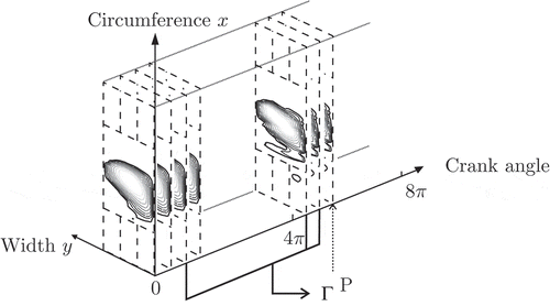
The main focus in this approach lies in the optimal choice of test space. In application to an IC engine, the available information, gathered in a previous combustion cycle by a detailed MBD simulation with EHD coupling, can be exploited by utilizing periodicity. That pressure solution, which arises in an equilibrium condition of the solids involved, is taken as reference. Optimally, the Petrov–Galerkin solution is equal to that found by projection of such a reference solution
and the ansatz functions
:
By equating (15) and (16), the definition of an optimal test space is obtained
The dimension of the null space corresponds to the number of nodes at which the Reynolds equation has been evaluated. According to the rank-nullity theorem, null
holds.
From (15), the additional condition, that the expression has to be a
matrix and invertible, is derived. Using an arbitrary real matrix
, the test space
can be obtained by
Two intuitionally chosen possibilities for the determination of denoting unity matrix
could be
The Petrov–Galerkin procedure described above did not consider boundary conditions yet. All matrices under consideration only include nodes in the lubrication region where Reynolds equation applies. The boundary conditions describing pressure in cavitation region and at nodes held at supply or ambient pressure are included as constraints into the optimization.
Solutions showed that best results could be achieved by optimization of the boundary conditions using Reynolds equation as constraint. Since this poses an optimization problem under equality constraints, Reynolds equation is implemented by Lagrange multipliers and the objective function is the Lagrange expression
A possible choice of reference solutions in the Petrov–Galerkin method is shown in A combination of solutions of the previous time steps and the previous combustion cycle can be used.
4.4. Cavitation detection
As the extent of cavitation region poses a free boundary condition, it has to be evaluated each time after a new solution has been found. In a full scale evaluation, the algorithm for detecting cavitation and solving Reynolds equation node by node is well established. A description of this algorithm with an application example for micro-textured bearings can be found in [Citation17]. Due to its highly nonlinear nature, the convergence of such a solution approach is analytically hard to prove, if feasible at all. In [Citation18], a detailed study is presented that discusses the convergence behaviour of the iterative procedure. Though no formal proof is given for the reasons stated above, the paper gives a clear indication on the robustness of the algorithm.
Therefore, the cavitation detection procedure for the reduced order model is based on the same principal ideas outlined in [17,18]. To do so, the modal coordinates have to be transformed into a spatial representation of pressure and fill ratio by means of the ansatz functions first. Based on these elements, the occurrence of cavitation has to be reassessed node by node before the next iteration step can be performed with now possibly different boundary conditions.
After a cavitation detection algorithm has decided which nodes belong to the cavitation region, the appropriate Equation (9a) or (9b) is applied in the next iteration step at the corresponding node. At the start of the iteration, this is done based on initial values, which can be taken from the final pressure distribution obtained in the preceding time step, for example.
Due to the approximation character of the solution as well as the optimization procedure, evidence for cavitation is not always distinct. Especially in domains where the transition to cavitation is not sharp, i.e. gradients are small and the pressure only approaches cavitation pressure slowly, detection can become problematic. Here, the pressure and fill ratio results can even lead to contradicting assertions.
To overcome such ambiguities, the fact is exploited, that opposed to the full scale evaluation in the modal evaluation a calculated pressure as well as a calculated fill ratio value exist at the same time for each node. As a minor extension to the known cavitation detection algorithm, basically two fill ratio thresholds are defined. For fill ratio values below a lower bound slightly below one, cavitation is assumed; above an upper bound, lubrication is assumed. If a fill ratio result lies in between these thresholds, additionally the ratio of pressure solution and cavitation pressure will be taken into account to decide on the onset of cavitation. Additional measures could include neighbouring nodes or time history to improve detection rate.
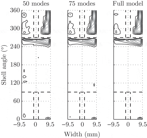
The application of the presented approach in various crank angle positions gained the experience that after typically three iterations the number of nodes in the cavitation region remains unchanged. Usually a convergent behaviour with respect to the number of modes used can be observed. shows a quantitative comparison of the fill ratio result at crank angle found by Condensed Galerkin with 50 and 75 modes, respectively, compared to the full model to illustrate the usually convergent behaviour with an increasing number of modes.
4.5. Approximation of Jacobian matrix using the reduced order model
In the MBD simulation, flexible solids are represented by discretized models. Multiple bodies such as crankshaft and bearing shell are coupled via joint forces, which are determined by the oil pressure in the clearance gap. To achieve an overall equilibrium, external nodal forces calculated for the solids and joint forces have to be equal. Body forces are considered as predicted and joint forces
as calculated. The latter indirectly also depend on body forces, therefore joint forces are a function of body forces and
holds [Citation19].
Equilibrium is established when the residual force becomes zero:
In the modified Newton–Raphson approach [19], which is applied in the MBD simulation procedure, the Jacobian matrix , describing the coupling, arises. Denoting the identity matrix by
, it is defined as
Therefore, the calculation of the Jacobian matrix can be reduced to the evaluation of joint force changes per body force variation. In other words, a variation of the body force at node j (i.e. one entry in
) is applied at a time and after solving the joint equation using this varied input, one column of the Jacobian matrix results. Thus, for a complete evaluation, Reynolds equation has to be solved as many times as there exist DOFs of the flexible bodies. As the finite volume grid usually consists of substantially more DOFs than the flexible bodies, a costly solution of Reynolds equation has to be found for each variation anew. Such a repeated evaluation of Reynolds equation to find the Jacobian matrix optimally in every time step poses the bottleneck in the MBD simulation.
The reduced order procedure is intended to decrease calculation time by using an approximation of the pressure solution in the calculation of the Jacobian matrix. The principles of the solution approach are based on analytic differentiation of the reduced order pressure result with respect to the clearance gap height and shall be described in the sequel.
Expanding the first addend on the right hand side of (24) into two parts, leads to
Herein, the first multiplier describes the joint forces change per gap height variation, whereas the second term can be seen as compliance matrix of the flexible bodies describing the gap height change per body force variation. The latter can be taken from the MBD simulation: however, the former can readily be found using the procedure described in this paper, thus exploiting the reduction of DOFs multiple times per evaluation of the Jacobian matrix.
The result of Reynolds equation is a pressure distribution, which is mapped to the joint forces by a constant transformation matrix according to
. Substituting, for example, the Flat Galerkin reduced order model of the pressure (11) for the first multiplier in (25) yields, with boundary condition entries omitted:
Using abbreviation in the well-known identity
The same procedure can be applied to Condensed Galerkin or Petrov–Galerkin solutions and leads to more complicated terms, which are not covered in this paper, though.
Using the scheme (28) in conjunction with the Galerkin reduced order model and the compliance matrix, the Jacobian matrix can be determined at a drastically reduced computational cost. The evaluation of a first academic example in Section 5.1 yields promising results, which encourage further research into this application.
5. Numerical results
The results presented in this section have been found for a single crankshaft main bearing for an inline IC engine of typical dimensions as it is depicted in Its diameter is , its width
. The bearing shell is divided into two segments. On the upper half of the shell – in relation to the orientation of the cylinder – an oil groove is located at the middle plain extending over
in circumferential direction. The split line between upper and lower shell also serves as oil supply over the whole bearing width. Both are indicated by dashed lines in the following figures. The oil (SAE 5-W30) is assumed to remain at a constant temperature of
, which corresponds to a dynamic viscosity of
. Surface roughness is assumed isotropic (i.e.
) with a composite roughness of 0.67 μm.
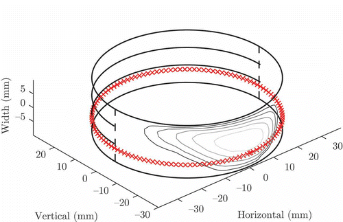
Figure 6. Bearing geometry with pressure contour in lower shell area and circumferential cut position.
As starting point for reduced order solutions and the generation of ansatz space, a detailed MBD simulation with EHD coupling at using the method, which is proposed in [2], has been performed over
crank angle. A 3D volume model of the bearing shell with 336 nodes is coupled with a structured beam mass model of the journal with 7 nodes (). In particular, 336 radial flexible shell DOFs are coupled with 2 DOFs per connected journal node, which results in 14 flexible journal DOFs in total. The EHD calculation is done using a finite volume grid with 1885 cells. The coupling of the MBD and the EHD domain is done using a modified Newton–Raphson approach [19].
Of these two combustion cycles, the first one is used to overcome transient effects due to missing initial conditions before returning valid results in the full procedure. The solutions in this initialization phase, containing 720 different crank angle positions of the first combustion cycle is used as collection of snapshots for the generation of ansatz functions for pressure and fill ratio. Here, the periodicity of the overall simulation is exploited as after the initialization cycle a reduced order model approximation is already available for subsequent cycles.
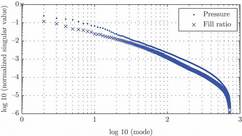
shows the decay of the normalized singular values of pressure and fill ratio ansatz functions. Subsequent results have been found by using bases containing 150 modes. In this case, this equals a decay of the normalized singular values below .
The reduced order model utilizes the detailed result at crank angle as initial value and results are presented at
. To consider a change in the extent of cavitation region, two iterations are performed. When more iterations are applied, the number of cavitation nodes remains constant, thus indicating that the algorithm converged. The generation of Petrov–Galerkin test space is based on the full solution at crank angles
.
In , the bearing geometry with oil supply groove and split line is shown. The pressure solution at crank angle is indicated by contour lines, cut position of and as crosses.
Figure 9. Pressure solutions found by Flat Galerkin, Condensed Galerkin and Petrov–Galerkin compared to the full solution shown as circumferential cut.
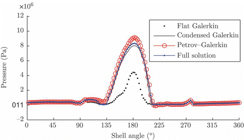
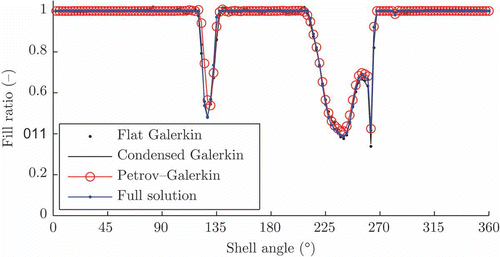
Figure 10. Fill ratio solutions found by Flat Galerkin, Condensed Galerkin and Petrov–Galerkin compared to the full solution shown as circumferential cut.
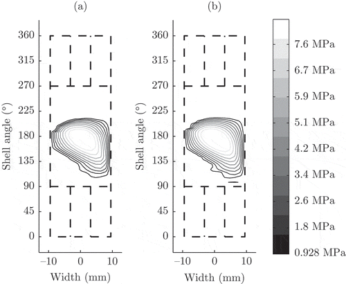
Bearing geometry is unrolled into a two dimensional representation in , comparing the pressure solution of the full model to the reduced order model solution, which has been found by Condensed Galerkin. Peak pressure amounts to 9.2 MPa. Both solutions are of very similar shape and differ only slightly.
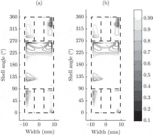
The same type of comparison for the fill ratio is shown in The intensity of grey corresponds to the strength of cavitation. Minimum fill ratio turns out to be 0.0156. Although the results are very similar in general, larger deviations can be observed than in the pressure solution.
A more detailed graphical evaluation of results offers a circumferential cut, whose position relative to the bearing can be seen in Each marker in represents the pressure solution at one of the nodes with same axial coordinate.
In relation to the full solution, Flat Galerkin with 150 modes in the ansatz space leads to a unusable result. The two other procedures reproduce the full solution well, thereby Condensed Galerkin slightly outperforms Petrov–Galerkin. A general trend in the review of various solutions is the fact, that an influence of the reference solution used in the generation of test space for Petrov–Galerkin on its reduced order solution is identifiable.
The same conclusion can be made for the fill ratio solution depicted in In contrast to the pressure solution, Flat Galerkin leads to a good result in this evaluation although this is not the case in general. The tendency of Petrov–Galerkin reproducing reference solutions is again evident in the evaluation of fill ratio.
For a quantitative comparison of solutions, the sum of absolute errors ; the average absolute error per node
as well as the overall sum of pressure
and fill ratio values
are listed in . It can be observed that Condensed Galerkin leads to the lowest absolute and relative errors.
Table 1. Quantitative comparison of solution methods for pressure and fill ratio results.
5.1. Approximation of Jacobian matrix
While in the preceding section the approximation capabilities of the Galerkin reduced order model have been discussed and illustrated, the next step will now be to demonstrate its applicability in the fast determination of the Jacobian matrix. Note that the result, which is shown below, still has to be multiplied with the compliance matrix to yield the final Jacobian matrix.
In this context, lines of action are defined for nine contact forces to
, which are unevenly distributed around the circumference. They are depicted in in addition to a simplified representation of geometry, which is considered rigid in this case. Moreover, supplemental contact forces
to
are defined, whose lines of action are passing through the origin of
and which are at the same time perpendicular to those corresponding to
to
. That is,
is pointing into the
direction, for example.
Figure 11. Axial view of the bearing with lines of action of the contact forces shown as dotted lines.
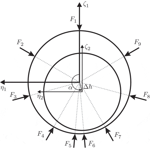
The intensity of each of these 18 forces is determined by integrating the pressure, which is projected onto the corresponding direction, over the circumference. As such a definition of forces is usually not used in a MBD simulation, the conducted comparison has to be considered as academic result to basically show the ability of the method.
Further, nine variations of gap height are applied. For that, the journal is translated as a whole by into directions
to
, wherein
describes the nine lines of action of
to
. Corresponding variations are denoted as
to
. In this example,
is chosen as
of the smallest gap height, which amounts to
m. The first part in the Jacobian matrix describing the contact force change per gap height variation is determined in two ways.
First, a pressure solution using the full basis is found for each gap height variation. The expression is calculated by numerical differentiation, i.e. subtracting the original reference solution without variation from the currently found solution with variation and then dividing by the gap height variation node by node. Thus, a numerically derived matrix
is obtained based on full solutions.
Second, the same expression is determined by using the reduced order model according to (28). This solution, denoted by , therefore can be found with reduced effort and is based on
modes.
To compare and
, an SVD is conducted. Both matrices should optimally describe the change of contact forces in their intensity and principal direction equally well. Singular values
should match with
and right-singular vectors should point into the same direction, that is their inner product
should be one or minus one.
shows such a comparison for the configuration described. The first two rows show the normalized singular values using . Therein, the first two values nearly match exactly. The others come out to be several magnitudes smaller, although they all still lie closely together. In the last row, the absolute values of the inner product of right-singular vectors
are shown. For the dominant singular values, their direction is again basically equal (i.e. their inner product is very close to one).
Table 2. Comparison of singular values and inner products of right-singular vectors of the two matrices and
describing contact force changes per gap height variation.
Considering these first results, the future application of a reduced order evaluation in the Jacobian matrix approximation seems promising.
6. Outlook
The methods proposed in this paper can reduce the number of DOF in the solution of Reynolds equation by approximately up to depending on the operating conditions and point in time under consideration. At the same time, they preserve good approximation quality characteristics in short-term calculations. Basically, the algorithm is applicable at every load level without adaption or non-physical input, except the dimension of ansatz space to be used.
In the multi-body simulation of IC engines, different contact models can be selected depending on the requirements. Compared to a powerful solver on today’s hardware, replacement of the full EHD evaluation of radial slider bearings under consideration of local effects and cavitation is not feasible with a reduced order model based on projection. However, switching from full to reduced order procedure and backwards can readily be implemented and a fast approximation of solution is available, which can be used as intermediate step in a Runge–Kutta method, for example. Application of the proposed method is directly possible to axial slider bearings or lubricated piston liner contacts as well.
As it has been shown, the approximation can beneficially be exploited in the calculation of the Jacobian matrix for coupling of MBD and EHD lubrication, which poses a key factor in the performance of the overall multi-body simulation procedure. To avoid time-consuming recalculations in the current algorithm, the Jacobian is kept constant over several time steps until a criterion like an alteration of damping coefficients or the exceeding of a maximum number of iterations is violated. Acceleration of the recalculation procedure of the Jacobian, which describes the coupling, using a reduced order model solution of the Reynolds equation could allow for more frequent updates and subsequently for better overall convergence properties. Since the pressure field is readily available, force derivatives can directly be applied to the pressure, leading to a reduced effort in their evaluation.
Another possible field of application is noise, vibration and harshness simulation, where a detailed resolution of cavitation region or fill ratio is not necessary and could be neglected therefore. In addition, these results could be used in an identification of coefficients needed in a spring-damper representation of the bearing.
Although further investigation especially of the properties of Petrov–Galerkin and a possibility for error diagnosis has to be performed, the methods proposed in this paper proved well in their designated implementation.
References
- O. Reynolds, On the theory of lubrication and its application to Mr. Beauchamp tower’s experiments, including an experimental determination of the viscosity of olive oil, Phil. Trans. R. Soc. Lond. 177 (1886), pp. 157–234.
- G. Offner, Modelling of condensed flexible bodies considering non-linear inertia effects resulting from gross motions, Proc. Inst. Mech. Eng. Pt. K J. Multi-body Dyn. 225 (2011), pp. 204–219.
- AVL List GmbH, AVL-EXCITE Reference Manual Version 2011, Reference Manual, AVL List GmbH, Graz, 2011.
- F.W. Ocvirk, Short bearing approximation for full journal bearings, NACA Tech. Note 2808, Cornell University, Ithaca, NY, 1952.
- A. Sommerfeld, Zur Hydrodynamischen Theorie der Schmiermittelreibung, Zeitschrift für Mathematik und Physik 40 (1904), pp. 97–155.
- J.F. Booker, Dynamically loaded journal bearings: Mobility method of solution, J. Basic Eng. 87 (1965), pp. 537–546.
- H.G. Elrod and M. Adams, A computer program for cavitation and starvation problems, in Cavitation and Related Phenomena in Lubrication: Proceedings of the 1st Leeds-Lyon Symposium on Tribology, Department of Mechanical Engineering, The University of Leeds, England, September 1974, D. Dowson, M. Godet, and C.M. Taylor, eds., Mechanical Engineering Publications for the Institute of Tribology, Leeds University and the Institut National des Sciences Appliquées de Lyon, London and New York, 1975, pp. 37–41.
- H.G. Elrod, A cavitation algorithm, J. Lubrication Technol. 103 (1981), pp. 350–354.
- J.H. Spurk and N. Aksel, Fluid Mechanics, 2nd ed., Springer-Verlag, Berlin Heidelberg, 2008.
- N. Patir and H.S. Cheng, An average flow model for determining effects of three-dimensional roughness on partial hydrodynamic lubrication, J. Lubrication Technol. 100 (1978), pp. 12–17.
- N. Patir and H.S. Cheng, Application of average flow model to lubrication between rough sliding surfaces, J. Lubrication Technol. 101 (1979), pp. 220–230.
- S. Thomas, Analyse des Betriebsverhaltens von Kurbelwellengleitlagern mittels TEHD-Berechnungen, Ph.D. diss., RWTH Aachen, 2003.
- S. Volkwein, Model reduction using proper orthogonal decomposition, Lecture Notes, Institute of Mathematics and Scientific Computing, University of Graz (2008). Available at http://www.uni-graz.at/imawww/volkwein/POD.pdf. (Accessed 9 January 2013).
- J. Krasser, Thermoelastohydrodynamische Analyse dynamisch belasteter Radialgleitlager, Ph.D. diss., Graz University of Technology, 1996.
- R. Temam, Infinite-Dimensional Dynamical Systems in Mechanics and Physics, 2nd ed., Applied mathematical sciences, Vol. 68, Springer-Verlag, New York, 1997.
- H.G. Matthies and M. Meyer, Nonlinear Galerkin methods for the model reduction of nonlinear dynamical systems, Computers & Structures 81 (2003), pp. 1277–1286.
- R. Ausas, P. Ragot, J. Leiva, M. Jai, G. Bayada, and G.C. Buscaglia, The impact of the cavitation model in the analysis of microtextured lubricated journal bearings, J. Tribology 129 (2007), pp. 868–875.
- R. Ausas, M. Jai, and G.C. Buscaglia, A mass-conserving algorithm for dynamical lubrication problems with cavitation, J. Tribology 131 (2009), pp. 031702–1–031702–7.
- G. Offner, Friction power loss simulation of internal combustion engines considering mixed lubricated radial slider, axial slider and piston to liner contacts, Tribology Trans. 56 (2013), pp. 503–515.

