 ?Mathematical formulae have been encoded as MathML and are displayed in this HTML version using MathJax in order to improve their display. Uncheck the box to turn MathJax off. This feature requires Javascript. Click on a formula to zoom.
ABSTRACT
Tubes are commonly used in pneumatic systems for transferring energy and control signals. Using the control volume method, a mathematical tube model has been developed, which takes into account the effect of resistance, capacitance and inertance on the dynamic properties of control and supply circuits of pneumatic systems. The adequacy of the computer model developed in Matlab/Simulink was verified by comparing the results of simulation studies with the results of experimental tests of airflow through tubes of varying diameter and length. The advantage of the computer model is the capability to model pneumatic systems under varying conditions of heat exchange with the environment by changing the coefficient of the polytropic process coefficient.
1. Introduction
Tubes are the main components of the majority of pneumatic pressure systems. The process of airflow through the tubes is of major importance because of the accompanying actuator feed pressure losses in the drive circuits or the pressure signal delay in the control circuits.
The behaviour of processes occurring during airflow through the tubes is very complex due to, among other factors, air compressibility and tube wall compliance under pressure (capacitance), air viscosity variation depending on pressure and temperature, the effect of friction in laminar and turbulent flows (resistance) and the air inertia effect (inertance). Under dynamic operation conditions, the combined effects of resistance, inertance and capacitance cause distortions and delays in pressure variations, thus affecting the dynamic characteristics and operation-service properties of the pneumatic drives.
The majority of pneumatic and hydraulic tube models are derived from the Navier–Stokes (N–S) equations [Citation1], being a system of general continuity, motion and energy equations. Typically, a series of assumptions are made to simplify these complex non-linear equations and to solve the above-mentioned system of partial differential equations.
There are several techniques available for time-domain simulations of transient flows in tubes [Citation2,Citation3]. These are the finite element method [Citation4], finite volume method [Citation5], characteristics method [Citation6], transmission line method [Citation7] and the method of the rational polynomial transformation of the approximation function [Citation8,Citation9], which is a form of the modal approximation method [Citation10,Citation11]. The experimental validation of selected tube airflow simulation methods carried out in study [Citation12] has shown their limited suitability for pneumatic system simulations, due to the complexity of the computer models or the numerical problems with solving them. As the most suitable method for signal-oriented simulation programs, such as Matlab/Simulink, the control volume method, called also the semi-discretization method (vertical line method), has been indicated [Citation13,Citation14]. It should also be remembered that in modelling of complex heterogeneous engineering systems [Citation15] it is necessary to realize the computer models of all system elements within a single, specified programming environment. The control volume method was used to the simulation of the respirator’s ventilation system [Citation16] or the aircraft pneumatic system [Citation17], among others, by assuming the isothermal flow behaviour. The heat exchange with the environment was taken into account in the mathematical pneumatic tube model in study [Citation18], using the Reynolds analogy between mass and heat transport. In the simplified model [Citation19,Citation20], the tube inertance was neglected, and the airflow through the resistance was described by an analytical equation.
In many instances, it is possible to determine in advance the character of thermal processes during airflow through the tubes. It has been therefore assumed in this study that the course of the thermal phenomena be formulated using the polytropic equation, which quite considerably simplifies the mathematical modelling of airflow through the tube, as it allows the elimination of the differential temperature equations (a reduced number of state equations). The mathematical model allows for the capacitance, resistance and inertance of the tube as phenomena important in modelling of transient processes, especially at large pressure variations in pneumatic systems. The computer model has been realized in the MatlaB/Simulink program which, as for now, has no advanced models for pneumatic tubes in its library, which are available in object-oriented programs, such as Dymola or Modellica [Citation14]. The developed computer model of the tube can be used for the simulation of transients in pneumatic systems subjected to large pressure changes, for example, vehicle brake systems.
2. The mathematical model of the tube
Considering the nonstationary airflow through the tubes, typical simplifying assumptions have been made:
Flowing air is treated as a compressible and thermodynamically perfect gas;
The state parameters and velocity of the gas are invariable in the flow cross-section, but are dependent on time, t, and one geometrical coordinate, x, which corresponds to the tube axis (one-dimensional flow);
External forces (e.g. gravity force) and internal friction are omitted;
The volumetric tube deformations are not omitted;
The behaviour of the thermal processes is described by the polytropic equation.
2.1. Capacitance
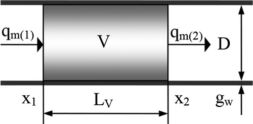
The change of mass in the separated control volume V of the tube () is described by the relationship:
where qm(i) is mass flux [kg/s] and ρ is density of gas in the control volume [kg/m3].
The first summand of the right-hand side of Equation (1) results from the tube compliance, while the second one, from the compressibility of air. By transforming the time derivative:
and assuming that
we obtain
where Cw is the tube (chamber) wall compliance [Pa−1]; for thin-walled tubes:
where D is inner tube diameter [m], E is Young’s modulus of the tube [Pa] and gw is tube wall thickness [m].
Using the polytropic equation in the differential form [Citation21]:
the second summand in Equation (1) can be presented in the following form:
After substituting Equations (2) and (4) in Equation (1), we obtain
For PA 12 PHL (in accordance with DIN 73378 standard) polyamide tubes with Young’s modulus of E = 350 MPa [Citation22], operating under a working pressure of p = 10 bar and at n = 1.4, the tube wall compliance Cw accounts for 2.6% of the compliance due to gas compressibility 1/(n∙p) for D = 16 mm and gw = 2 mm, and over 4.5% for D = 34 mm and gw = 3 mm. The above calculations substantiate the need for considering the tube wall compliance in calculating the general capacitance, especially in the case of a large inner diameter of the tube and a high working pressure value.
Equation (5) can also be presented in the form as follows:
where C1 is capacitance resulting from the deformation of the control volume V [kg/Pa] and C2 is capacitance due to the compressibility of gas in the chamber [kg/Pa].
By expressing the gas density in Equation (5) with pressure in the polytropic process, as in study [Citation13]:
upon making transformations, the differential equation for pressure in the control volume is obtained as follows:
For the pipe (chamber) wall compliance Cw = 0, the expression in the denominator on the right-hand side of Equation (8) is reduced to a relationship for C2.
2.2. Resistance
The pressure losses in the tube, including the inlet losses and the losses due to tube bending, are as follows:
where λf is dimensionless linear resistance coefficient, ξ is dimensionless local resistance coefficient, w is mean flow velocity [m/s] over the length LV of the tube segment.
The dimensionless local resistance coefficients of typical tube fittings and curved segments can be determined from published data [Citation23].
Using the relation between the mass flux and the averaged flow velocity:
the pressure drop (Equation (9)) can be made dependent on the mass flux:
where A is flow surface area [m2].
The relative surface roughness of plastic tubes with an inner diameter of up to 22 mm is smaller than 3.125∙10–4; thus, the linear loss factor can be calculated as for smooth tubes [Citation24], e.g. from the relationship [Citation13,Citation25]:
2.3. Inertance
The effect of inertance is described by the following equation:
As m = ρ∙LV∙A and w = qm/(ρ∙A), so
By combining the resistance with the inertance, a relationship for the total pressure drop is obtained, as follows:
from which, after transformations, the differential equation for the mass flux is obtained:
As the linear resistance factor λf is dependent on the Reynolds number:
then, to simplify the numerical computation, this criterion number can be directly substituted in Equation (16):
where η is air dynamic viscosity [Pa·s] as calculated from the relationship [Citation26]:
where η0 is value of air dynamic viscosity at the reference temperature T0.
In Equations (18) and (19), for the density and dynamic viscosity of the gas, their mean values, ρ = ρm and η = ηm, should be substituted. The mean air density is calculated for the known density ρ1 at the inlet and density ρ2 at the outlet of the tube segment under consideration [Citation27]:
After taking account of Equation (7) in Equation (2) and making due transformations, we obtain
Whereas, the averaged viscosity value is calculated from Equation (19) for the mean temperature value:
where pm is mean pressure calculated as the arithmetic mean [Citation27,Citation28]:
or from the more accurate relationship [Citation28]:
3. The mathematical description of the discretized tube model
The choice of the degree of discretization of the mathematical model is a trade-off between the accuracy and computing performance of the digital simulation program. Assuming the limiting forcing action time in modelling pneumatic tubes to be equal to 0.04 s and the speed of sound, approx. 340 m/s, the maximum length of the tube segment for the control volume V corresponding to ¼ of the resonance wave length is equal to LV = 3.4 m [Citation18].
An example of the developed physical model of a tube ended with a resistance at either end, designed for joining pneumatic elements of the volume type, is shown in . The tube model consists of N identical lumped volumes V, representing capacitance, with corresponding tube segments of the length LV. Resistance and inertance are assigned to N + 1 tube segments, whereas the central segments, in the number of N − 1, each have the length LV, and the extreme segments are two times shorter, i.e. they have the length LV/2, each.
For the number of segments N > 1 (), the mathematical tube model consists of
N + 1 differential equations for mass fluxes:
(25)
(25)
N differential equations for pressure in individual control volumes V:
(26)
(26)
For a single-segment tube, N = 1, the tube model is reduced to two mass flux differential equations and one pressure differential equation:
The pressure drop Δp(i) = f(qm(i), Tm(i), ρm(i), λf(i), ξ(i), L(i)) in the tube segment due to linear and local resistances is calculated as dependent on the Reynolds number:
This Reynolds number can be either negative or positive, depending on the flux flow direction. Hence, finally,
where L(i) – tube segment length; for the extreme segments, L(i) = LV/2; for the central segments, L(i) = LV.
Equation (29) describing the pressure loss, due to friction along a given length of pipe segment, enables the modelling of local resistance of entries, exits and fittings (elbows, bends, etc.) expressed by ξ(i) coefficient, and the modelling of linear resistance for straight, helically coiled or spirally coiled tubes expressed by λf(i) coefficient.
Using Hook’s law to determine the hoop stress in a thin-walled elastic tube [Citation29], the diameter Dc and the cross-sectional area Ac of the tube under an internal pressure can be calculated as follows:
where pa is atmospheric pressure [Pa].
These new expressions for the tube diameter and the cross-sectional area can be introduced to Equations (25), (27), (28) and (29) in order to give a precise account of the tube deformation in the mathematical model.
The equations of the mathematical model can be related to two different and extreme assumptions presented simultaneously, by using the coefficient n of the polytropic process. For n = 1, it is assumed that the flow is isothermal and the air density is directly proportional to pressure. For n = 1.4, the flow can be regarded as ‘quasi-steady isentropic’ [Citation13].
4. The validation of the model
The literature results of experimental tests [Citation13] carried out on the test apparatus, the schematic diagram of which is shown in , were used for the validation of the computer model. The tests involved the flow of air through test tube 5 during filling and emptying of container 6 with volume Vex, positioned at the end of the tube. In the transition process, after readjusting directional valve 4, air pressure in emptied container 3 and in container 6 positioned after the tested tube was recorded using transducers 7. The employed fast-acting directional valve 4 provided a stepwise pressure increase or drop at the tube inlet, which was established experimentally. Feed pressure pin upstream the distributor was stabilized by container 3 with a relatively large volume Vr.
Figure 3. A schematic diagram of the test apparatus according to [Citation13]: 1 – compressed air source, 2 – pressure reducing valve, 3 – feed container, 4 – 3/2 directional control valve, 5 – test tube, 6 – container, 7 – pressure transducer, 8 – input-output adapter, 9 – computer with a measuring card (recorder).
![Figure 3. A schematic diagram of the test apparatus according to [Citation13]: 1 – compressed air source, 2 – pressure reducing valve, 3 – feed container, 4 – 3/2 directional control valve, 5 – test tube, 6 – container, 7 – pressure transducer, 8 – input-output adapter, 9 – computer with a measuring card (recorder).](/cms/asset/4e28c4aa-c16c-49b7-ab1f-15dc8efdcbd3/nmcm_a_1280512_f0003_b.gif)
Making the assumption of the stepwise increase or decrease of pressure pin at the tube inlet, directional valve 4 can be disregarded in the mathematical model, thus reducing the pneumatic model shown in to two volumes, Vr and Vex, connected with the tube. The desired direction of airflow through the tube (filling or emptying container 6) is achieved by assuming respective initial pressure values in individual components of the modelled system. The computer models of the containers and the tube were realized in the Matlab/Simulink program as masked subsystems using the S-function structure [Citation30].
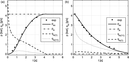
Examples of the results of transition process simulation during filling and emptying the chamber of volume Vex = 150.76 cm3 (9.2 in3) through the tube under isothermal flow conditions (n = 1) for the number of segments N = 10 are shown in . In order to stabilize the value of feed pressure pin, container 3 was assumed in the computer model to have a volume of Vr = 20000 dm3.
Figure 4. The results of simulation of pressure variations in the tube end chamber during: a – filling, b – emptying; Vex = 150.76 cm3 (9.2 in3); L = 30.48 m (100 ft), D = 4.318 mm (0.17 in), pin = 4.137 bar (60 psi), Tin = 299.816 K (80°F).
To validate the computer model, simulation studies were conducted for an inner diameter of D = 4.318 mm (0.17 in) and D = 6.35 mm (0.25 in) and a tube length of L = 30.48 m (100 ft), L = 60.96 m (200 ft), L = 121.92 m (400 ft). All studies were carried out using the ode45 solver procedure (Dormand-Prince) for the identical number of segments (tube control volumes) N = 10, corresponding to 11 nodes adopted in [Citation13]. The results of the simulation studies of pressure in the chamber of a volume of Vex = 150.76 cm3 with two extreme polytropic process coefficient values of n = 1 and n = 1.4, as juxtaposed with the pressure experimental test results [Citation13], are illustrated in –.
Figure 5. Pressure variations in the tube end chamber during: a – filling, b – emptying; Vex = 150.76 cm3 (9.2 in3); L = 30.48 m (100 ft), D = 4.318 mm (0.17 in), pin = 4.137 bar (60 psi), Tin = 299.816 K (80°F).
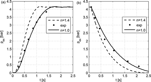
Figure 6. Pressure variations in the tube end chamber during: a – filling, b – emptying; Vex = 150.76 cm3 (9.2 in3); L = 60.96 m (200 ft), D = 4.318 mm (0.17 in), pin = 4.137 bar (60 psi), Tin = 299.816 K (80°F).
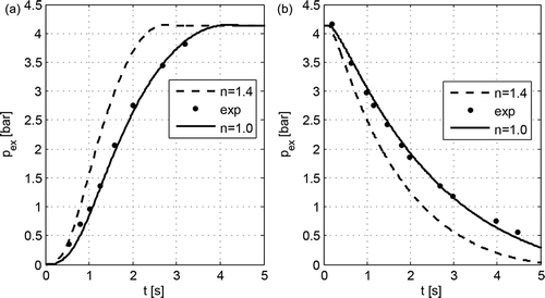
Figure 7. Pressure variations in the tube end chamber during: a – filling, b – emptying; Vex = 150.76 cm3 (9.2 in3); L = 60.96 m (200 ft), D = 6.35 mm (0.25 in), pin = 4.137 bar (60 psi), Tin = 299.816 K (80°F).
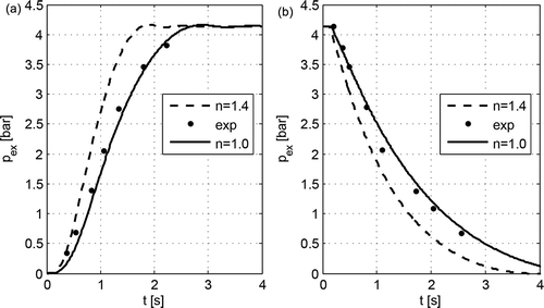
Figure 8. Pressure variations in the tube end chamber during: a – filling, b – emptying; Vex = 150.76 cm3 (9.2 in3); L = 121.92 m (400 ft), D = 6.35 mm (0.25 in), pin = 4.137 bar (60 psi), Tin = 299.816 K (80°F).
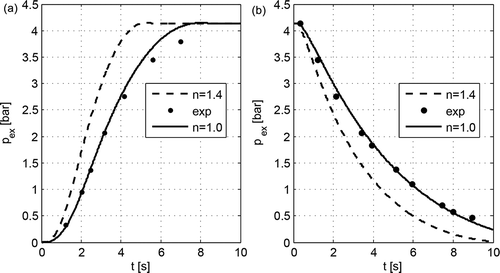
The obtained simulation study results indicate that a better consistence with the experimental test results is provided by making the assumption of the isothermal behaviour (n = 1) of airflow through the tube and the assumption that the flow is quasi-steady isentropic (n = 1.4).
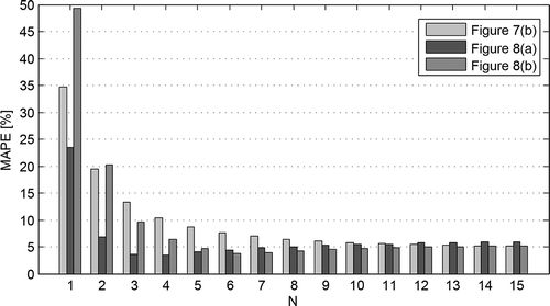
Preliminary simulation studies showed that the adequacy of the computer model of tube can be improved through a proper selection of some parameter values, including the local ξ and linear λf friction factors and the degree of model discretization. The obtained experimental and simulation results were used to estimate the influence of the number N of tube segments (changing from 1 to 15) on the accuracy of simulation results. The modelling performance was assessed using the mean absolute percentage error (MAPE), defined as [Citation31] follows:
where k is number of values in each of the sets, pi is measured pressure in volume Vex, pmi is corresponding pressure determined from the model.
An example plot of the MAPE for some data sets is given in .
It was found that for most data sets the model’s performance is the best for N equals 4 (, MAPE = 3.53%), N equals 6 (, MAPE = 3.81%) or N equals 8 (, MAPE = 5.04%). When the number of segments is increased more, the model’s performance deteriorates (). But for other data sets an increasing degree of discretization causes a steady decline in the value of error. For example, for data set from the minimum of MAPE is 4.41% for N = 15 (). An increasing the number of segments for more than 10 does not result in significant improvement in the computational performance.
5. Summary
The mathematical and computer model of the pneumatic tube with lumped parameters, developed for one-dimensional flow using the control volume method, considers the effect of capacitance, inertance and resistance (linear and local resistances) on the dynamic characteristics of the pneumatic systems. An advantage of the model is the possibility of allowing for, in an indirect manner, the thermal phenomena accompanying the airflow through the tube by selecting the values of the polytropic process coefficient: for n = 1, the process is regarded as isothermal, and for n = 1.4 the flow has a quasi-steady isentropic behaviour.
For large pressure changes, the results of the simulation studies of the process of filling and emptying the chamber of a volume of Vex = 150.76 cm3 through the tube of an inner diameter of 4.318 and 6.35 mm and a length of 30.48, 60.96 and 121.92 m, respectively, have shown agreement with the experimental test results for the isothermal flow, indicating the usefulness of the developed model for computer simulation of the dynamics of pneumatic systems. In some cases for small pressure changes [Citation13], the experimental data appear to be closer to the pressure calculated for the quasi-steady isentropic flow.
Nomenclature
| A | = | flow surface area [m2] |
| C1 | = | capacitance resulting from the deformation of the control volume [kg/Pa] |
| C2 | = | capacitance due to the compressibility of gas in the chamber [kg/Pa] |
| Cw | = | tube wall compliance [Pa−1] |
| D | = | internal tube diameter [m] |
| E | = | Young’s modulus of tube [Pa] |
| gw | = | tube wall thickness [m] |
| L | = | tube length [m] |
| LV | = | segment length [m] |
| m | = | mass of air in the tube segment [kg] |
| n | = | polytropic exponent |
| N | = | number of tube segments (volumes) |
| p | = | absolute pressure [Pa] |
| qm | = | mass flux [kg/s] |
| R | = | air gas constant [J/(kg∙K)] |
| t | = | time [s] |
| T | = | absolute temperature [K] |
| V | = | control volume [m3] |
| w | = | mean flow velocity [m/s] |
| ηo | = | dynamic viscosity at reference condition [Pa∙s] |
| λf | = | dimensionless linear resistance coefficient |
| ξ | = | dimensionless local resistance coefficient |
| ρ | = | air density [kg/m3] |
| ρm | = | average segment air density [kg/m3] |
Acknowledgment
This research was sponsored by Rector’s project no. S/WM/2/2013.
Disclosure statement
No potential conflict of interest was reported by the author.
Additional information
Funding
References
- I.G. Currie, Fundamental Mechanics of Fluids, Fourth ed., CRC Press Taylor & Francis Group, Boca Raton, London, New York, 2013.
- R. Goodson and R. Leonard, A survey of modeling techniques for fluid line transients. Transactions of the ASME, J. Basic Eng. 94 (2) (1972), pp. 474–482. doi:10.1115/1.3425453
- M. Soumelidis, D. Johnston, K. Edge, and D. Tilley, A Comparative Study of Modelling Techniques for Laminar Flow Transients in Hydraulic Pipelines, Proceedings of the 6th JFPS International Symposium on Fluid Power, Tsukuba, November 7-10, 2005, pp. 100–105).
- C. Bisgaard, H. Sørensen, and S. Spangenberg, A finite element method for transient compressible flow in pipelines, Int. J. Numer. Methods Fluids 7 (3) (1987), pp. 291–303. doi:10.1002/(ISSN)1097-0363
- Y. Chen, F. Gao, Z. Zhang, H. Wang, and G. Cai, Finite volume model for quasi one-dimensional compressible transient pipe flow, (I) Finite volume model of flow field, Journal of Aerospace Power 23 (2) (2008), pp. 311–316.
- J. Manning, Computerized method of characteristics calculations for unsteady pneumatic line flows, Transactions ASME, Journal Basic Engineering, Ser. D 90 (2) (1968), pp. 231–240. doi:10.1115/1.3605084
- P. Krus, K. Weddefelt, and J.O. Palmberg, Fast pipeline models for simulation of hydraulic systems, Transaction of ASME, Journal of Dynamics Systems, Measurement and Control 116 (3) (1994), pp. 132–136. doi:10.1115/1.2900667
- W. Franco and M. Sorli, Time‐domain models for pneumatic transmission lines, Bath Workshop on Power Transmission and Motion Control, PTMC (2004), pp. 257–269.
- A. Almondo and M. Sorli, Time Domain Fluid Transmission Line Modelling using a Passivity Preserving Rational Approximation of the Frequency Dependent Transfer Matrix, Int. J. Fluid Power 7 (1) (2006), pp. 41–50. doi:10.1080/14399776.2006.10781238
- C. Hsue and D. Hullender, Modal approximations for the fluid dynamics of hydraulic and pneumatic transmission lines, in Proceedings of ASME Winter Annual Meeting on Fluid Transmission Line Dynamics, M.E. Franke and T.M. Drzewiecki, Eds., ASME, New York, 1983, pp. 51–77.
- J. Makinen, R. Piche, and A. Ellman, Fluid transmission line modeling using a variational method, Transactions of the ASME, Journal of Dynamic Systems, Measurement and Control 122 (1) (2000), pp. 153–162. doi:10.1115/1.482449
- S.V. Kirchel and O. Sawodny, Dynamic modeling of pneumatic transmission lines in Matlab/Simulink, Proceedings of the International Fluid Power and Mechatronics Conference, Beijing/China, August 17-20th (2011), pp. 24–29.
- J.E. Funk and T.R. Robe, Transients in pneumatic transmission lines subjected to large pressure changes, Int. J. Mechanical Sci. 12 (3) (1970), pp. 245–257. doi:10.1016/0020-7403(70)90042-1
- Modeling of Pneumatic Systems. Tutorial for the Pneumatics Library. Dassault Systèmes AB IDEON Science Park SE-223 70 LUND, (2010). http://marketing.intrinsys.co.uk/V6_2013x_PDir/pdf/catia_dbm_pneumatics_library.pdf (23.08.2016).
- M. Reeßing, U. Döring, and T. Brix, Modeling of heterogeneous systems in early design phases, in: F.-L. Krause. (Eds.), The future of product development. Proceedings of the 17th CIRP Design Conference, Springer, Berlin Heidelberg, 2007, pp. 247–258,
- Y. Shi, S. Ren, M. Cai, W. Xu, and Q. Deng, Pressure dynamic characteristics of pressure controlled ventilation system of a lung simulator, Comput Math Methods Med. 2014 (2014), pp. 1–10. article ID 76712. doi:10.1155/2014/761712
- J. Čižmár, Simulation of dynamic qualities of the aircraft pitot-static system, Mechanics Transport Communications. issue 1, article No 0063 (2006), pp. 1–10. http://mtc-aj.com/library/63_EN.pdf
- Z. Kamiński, Mathematical Modeling of Pneumatic Pipes in a Simulation of Heterogeneous Engineering Systems. ASME, J. Fluids Eng.. 133, 12 (2011), pp. 121401–121407. doi:10.1115/1.4005261
- Z. Kamiński, Simulation and Experimental Testing of the Pneumatic Brake Systems of Agricultural Vehicles, Oficyna Wydawnicza Politechniki Białostockiej, Białystok, 2012.
- Z. Kamiński, Determination of flow coefficient of pneumatic pipelines, Pneumatyka, 68. 3 (2008), pp. 33–36.
- P.K. Nag, Basic and Applied Thermodynamics 2/E, Tata McGraw-Hill Publishing Company Ltd., New Delhi, 2010.
- Catalog 2014. Mebra plastic Italia s.p.a. http://www.mebraplastik.com/images/layout/download/Catalogo.pdf (23.08.2016)
- I.E. Idelchik, Handbook of Hydraulic Resistance, 4th ed., edition revised and augmented, CRC Begell House, New York, CT, 2007.
- SMC (China) Co., Ltd., Modern Practical Pneumatic Technology, China Machine Press, Beijing, 2008. (Chinese)
- J. Guo and P.Y. Julien, Modified log-wake law for turbulent flow in smooth pipes, J. Hydraulic Res. 41 (5) (2003), pp. 493–501. doi:10.1080/00221680309499994
- Pipe Flow Calculation. Specific gravity, gas mixture density, specific volume, pressure levels. http://www.pipeflowcalculations.com/pipe-valve-fitting-flow/density-viscosity-specific-volume.php (23.08.2016)
- R.K. Shah and D.P. Sekulic, Fundamentals of Heat Exchanger Design, John Wiley & Sons, Inc, Hoboken, New Jersey, 2003.
- E.S. Menon, Gas Pipeline Hydraulics, CRC Press Taylor & Francis Group, Boca Raton, 2005.
- W.C. Young, R.G. Budynas, and A.M. Sadegh, Roark’s Formulas for Stress and Strain, 8th ed., The McGraw-Hill Companies, Inc, New York, 2012.
- Simulink. Developing S-Functions. The MathWorks, Inc, Natick, 2015. http://www.mathworks.com/help/pdf_doc/simulink/sfunctions.pdf (23.08.2016)
- J. Zurada, A. Levitan, and J.A. Guan, Comparison of Regression and Artificial Intelligence Methods in a Mass Appraisal Context, J. Real Estate Res. 33 (3) (2011), pp. 349–387.

