
 ?Mathematical formulae have been encoded as MathML and are displayed in this HTML version using MathJax in order to improve their display. Uncheck the box to turn MathJax off. This feature requires Javascript. Click on a formula to zoom.
ABSTRACT
The application of Dual Mass Flywheels (DMF) was inspired by the need to reduce the level of vibrations generated by the drivetrain. The DMF input parameters are a result of the engine operation, in which the cyclicity of the subsequent strokes results in a variation of the engine speed. The fewer the cylinders the greater the engine speed variation and fluctuation of the engine torque. Additionally, the engine speed and torque variations are influenced by distortions, which is why the author attempted to develop a mathematical model of a DMF based on the motion equation. The methodology of calculations was also presented. For simplification, the moment of resistance generated by the drivetrain was assumed as constant. The simulation model checked out as correct and its sensitivity to small changes of the input parameters was confirmed. The mathematical description, despite simplifications, may find application in modelling of drivetrains fitted with DMF.
1. Introduction
A continuous advancement of the automotive industry inevitably forces an increase in the driving comfort. In terms of the suspension system, the matters related to the driving comfort have been gradually improved. A series of improvements has been introduced in the intake/exhaust systems to reduce the noise level. Modern drivetrains have been equipped with a Dual Mass Flywheel (DMF). The reason for this was that fact that the torsion dampers fitted in regular clutch discs have reached their operating limit. The increase in the engine power and torque exceeded the capacity of classic torsion damping. Since mid 1980s of the last century, the technology of dual mass flywheels has been continuously improved [Citation1–Citation7].
The growing expectations related to the driving comfort forced an introduction of increasingly more efficient torsion dampers [Citation8–Citation10]. The greater the engine torque, the greater the torsion vibrations of the engine due to the increasing amplitude, particularly at lower engine speeds [Citation11].
In the 1980s of the last century, LuK (Lamellen Und Kupplungsball) [Citation12] initiated research, the result of which was a development of a dual mass flywheel [Citation1,Citation12]. The new design allowed isolating the torsion vibrations of the engine from the rest of the drivetrain ().
Figure 1. Damping characteristics of the torsion dampers.
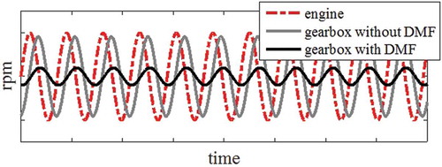
In the conventional solution, the resonance occurs at approximately 1500 rpm (effective diesel engine speed). With long DMF springs, the resonance occurs at approximately 300 rpm, which is below the operating range of a combustion engine [Citation6,Citation11,Citation13]. In this way, the drivetrain vibrations are reduced. Otherwise they would be transferred on the vehicle body [Citation7,Citation9,Citation11,Citation14–Citation18]. The outstanding issue is the DMF durability throughout the vehicle life cycle [Citation19,Citation20].
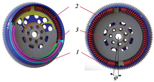
The principle of operation of a DMF is similar to a conventional torsion damper, fitted in the clutch disc. The difference is the increased torsion angle and fitting diameter of the springs. The engine torque is an input value on the primary mass 1 () fixed to the driveshaft with bolts and a locking pin. Then, from the primary mass the torque is transferred to the secondary mass 3 via a set of springs 2. The value of the torque is decisive of the torsion rate of the secondary mass against the primary mass and the friction among the contacting components of relative displacement is responsible for the actual damping.
Figure 2. Typical DMF used in passenger car drivetrains: 1 is the primary mass, 2 is a set of springs, 3 is the secondary mass, φ is the angle of the secondary mass torsion against the primary mass.
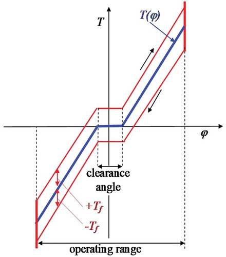
The DMF characteristics (relation of the engine torque and the torsion angle) may be linear or non-linear [Citation5,Citation13,Citation21,Citation22]. Usually, it is progressive with a visible loop of hysteresis resulting from mutual friction of the components and the friction between the springs and the spring guides ().
Figure 3. General characteristics of the torsion damper: T(φ) is the torque transferred by the DMF (friction excluded), Tf is the value of internal friction.
The characteristics are made up with groups of springs that, depending on the increasing load, may individually engage [Citation2,Citation8,Citation23]. The determination of the characteristics of a DMF is performed on special measurement stands generating swinging shocks [Citation5,Citation13,Citation21].
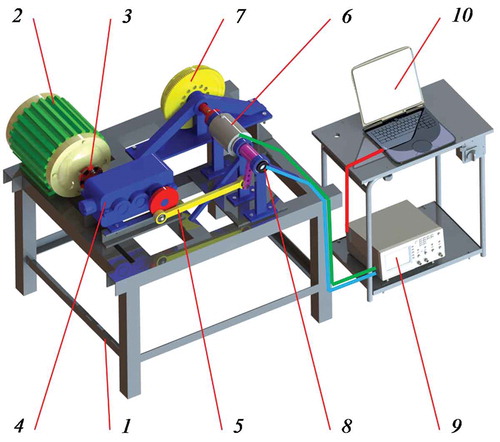
An example solution of such a stand has been presented in . The components are based on frame 1 (). Driving motor 2 transfers the torque to lever system 5 (the lever forces the swinging motion of the input shaft connected with primary mass 7) through clutch 3 and reducer 4 (the secondary mass is still). Torque meter 6 reads the current value of torque and rotary encoder 8 refers it to the instantaneous torsion angle. The signals are recorded and processed using measurement card 9 and computer 10 with dedicated software [Citation13].
Figure 4. Example measurement stand: 1 – frame, 2 – driving motor, 3 – clutch, 4 – reducer, 5 – connecting rod, 6 – torque meter, 7 – Dual Mass Flywheel (DMF), 8 – rotary encoder, 9 – measurement card, 10 – computer with dedicated software.
A general mathematical description of the DMF static characteristics with constant internal friction may be expressed with [Citation13]:
where TDMF(φ) is the torque transferred by the DMF (friction included), dφ/dt is the angular speed of the secondary mass torsion against the primary mass.
The obtained DMF characteristics are applied in modelling of the vehicle drivetrain operation [Citation7]. To this end, an attempt was made to develop a simplified mathematical model of the DMF – based drivetrain for different variants of distortions from the engine. The distortions mainly result from the operation of individual cylinders following uneven fuel dosage [Citation24].
A dual mass flywheel additionally generates issues in misfire identification [Citation25] or an accurate analysis of the engine torque curve [Citation26].
2. Mathematical modelling
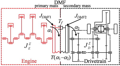
Both the range and level of complication of the mathematical model describing the DMF operation may slightly vary [Citation2,Citation5,Citation6,Citation27], which is why the author attempted to simplify it. For the description of the model, a diagram was adopted, as shown in .
Figure 5. Diagram adopted for the mathematical model.
2.1. Engine
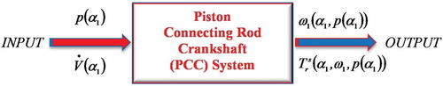
The electric input and output signals of the Piston-Connecting rod-Crankshaft (PCC) assembly have been shown in . From the above, we know that both angular velocity signal ω1 and engine torque signal Tr must contain information on the correctness of the process p(α1).
Figure 6. Input and output signals in the Piston-Connecting rod-Crankshaft (PCC) system.
The course of energy transformation in PCC with rotary input can be described [Citation28];
In Equation (2) ω and Tr are measures of vectors and
, while the square matrix [aij] describes the transmittance of the model of the object under consideration. Tr is the moment of the gas and inertia forces transferred from the connecting rod to the crank.
The rate of change in volume will be:
where V(α1) is function changes the volume of the chamber above the piston (4-stroke engine ;
); V`(α1) is geometric rate of change of volume; ω1 = dα1/dt is angular speed of the crankshaft.
Velocity of the piston will:
where v(α1) is piston speed, Ap is piston area.
The energy flow at the input:
where p(α1) is the pressure course in the cylinder as a function of the angular position of the engine crankshaft.
The energy flow at the output:
or as a function of time t:
wherein:
where τ is the number of revolutions per working cycle (4-stroke engine τ = 2).
The average cycle angular speed can be write:
The average power in the cycle will be:
The kinematics of the system shows the dependence:
where D is the operator of differentiation versus time (,
); Dc is diameter of the cylinder; x is displacement of the piston.
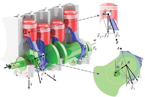
From the PCC layout geometry () it appears that:
Figure 7. The forces in the Piston-Connecting rod-Crankshaft (PCC) system.
or an approximate equation of the piston path:
where R is the crank radius, L is the length of the connecting rod, λ is the connecting rod coefficient L/R.
therefore:
By adopting a perfectly rigid system:
The torque equation will take the form:
Vector equation () describing the movement of the piston:
however, the acceleration will be:
The gas force acting on the piston:
where i – see .
The force acting in the connecting rod axis:
where l – see .
The resistance force of mass inertia in reciprocating motion:
where mA is the weight of the PCC components involved in the reciprocal motion (piston mass, gudgeon pin with protection, piston rings and part of connecting rod mass).
Moment is the result of the tangential force
acting on the crank ():
The summing up of the curves of torque generated by the gas force and the moment of inertia of the rotational masses will determine the total engine torque. Because rt = -k ():
where k – see .
or
So the words of the matrix [aij]:
The general equation of the energy process in PCC:
In four stroke, four cylinder engines, in which the work cycle involves two full crankshaft revolutions (angle 4π) and even distribution of ignitions, the crankshaft turns by the angle of π.
The Sx(α1) function for the four-cylinder engine will be:
while:
After each ignition and the pressure curves can be written as:
The equation of torque instantaneously generated by the engine at a constant load can be presented in the form [Citation9,Citation29]:
where α1 is the angle of crankshaft rotation, ω1 is the angular speed, ε1 is the crankshaft acceleration.
At times, when the instantaneous torque is greater than the average one the instantaneous speed increases. When the average torque is greater, the instantaneous crankshaft speed decreases. This is the result of the fact that mechanical work of the engine is equal with the increase in the kinetic energy accumulated in the rotating masses of the engine components, including the flywheel. When we compare the work and the energy, we may calculate the instantaneous angular crankshaft speed [Citation28,Citation29]:
The mass moment of inertia of the rotating elements of the engine will be:
Simplistically [Citation29]:
where JC is the crankshaft mass moment of inertia, JDMF1 is the DMF primary mass moment of inertia, mB is the replacement mass of the part of the connecting rod rotating on radius R of the x-th crank.
2.2. Dual Mass Flywheel (DMF)
If we want to describe the operation of a dual mass flywheel we can utilise on the motion equation for the case presented in . The equation takes the form [Citation13,Citation30–Citation32]:
where is the moment of inertia of the engine rotating masses including the DMF primary mass DMF;
is the moment of inertia of the drivetrain rotating masses including the DMF secondary mass DMF; T(α1-α2) is the torque transferred by the DMF, Tf is the moment of clutch friction;
are acceleration; angular speed and angle of rotation of the masses related to
;
are acceleration; angular speed and angle of rotation of the masses related to
.
2.3. Transmission
For the purpose of simplification, the moment of resistance generated by the drivetrain can be assumed as constant.
3. Input data, initial conditions
A flywheel of the characteristics shown in was selected for research.
Figure 8. DMF characteristics.
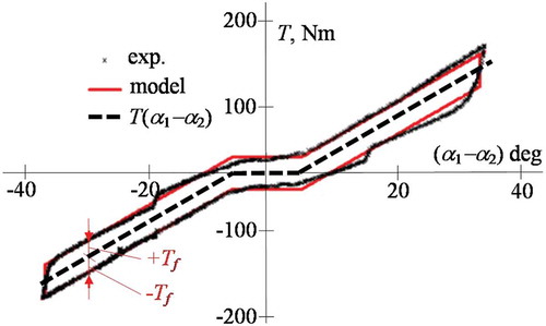
The moment of friction can be assumed at Tf = 26.84 N· m while the torque transferred by the DMF (friction excluded) has been described in [Citation13]:
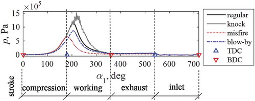
The input curves of pressure inside the cylinder (indicator graphs) necessary to determine the instantaneous engine speed have been shown in . The individual variants are: regular combustion, knock combustion, misfire and blow-by [Citation33].
Figure 9. The curves of the indicated pressures.
The outstanding data necessary to initiate the calculations have been presented in .
Table 1. Input data.
For each simulation, the author assumed that a distortion from the engine would be generated in the third cylinder. The moment of resistance was constant and had the value corresponding to the average value from the entire curve.
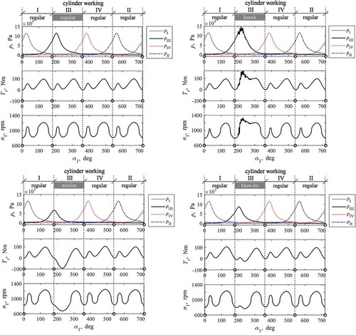
In the beginning of the calculations, for each of the calculated cases, curves of engine torque and speed were generated (based on the angular speed) ().
Figure 10. Curves of the pressure in cylinders, engine torque and speed (I, II, III and IV – cylinder).
Where n1 is the rotation speed of the engine and the DMF primary mass:
4. Results and discussion
The calculations were performed using Matlab-Simulink. For the Equation (33) a block diagram was drawn . The differential Equation (37) was solved numerically with the implicit trapezoidal method combined with reverse differentiation (accuracy 1e-12). For the Equation (37), the input instantaneous engine speed was linearly interpolated for the required moment of time. Input data are the angular speed of rotation of the engine and the DMF primary mass. Output – angular speed of rotation of the DMF secondary mass and the drivetrain. The angular speed of rotation was calculated to rotation speed.
Figure 11. Block diagram – Matlab-Simulink.
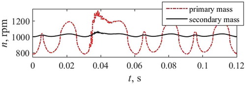
As a result of the performed calculations, curves of angular speeds were obtained as a function of time referred to the DMF primary and secondary masses. For better understanding, the results are presented in relation to the engine speed ().
Figure 12. Example speed curves of the DMF primary and secondary masses.
(distortion 2 in the third cylinder – knock combustion).
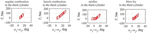
We can see varied values of the DMF angular displacements () depending on the adopted distortion variant. It is particularly the knock combustion and misfire that generate excess ‘work’ of the DMF, which results from the consequent engine work cycles.
Figure 13. DMF operating range depending on the variant – distortion in the third cylinder.
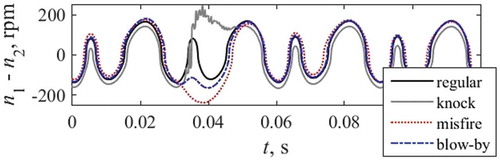
The differences in the speeds for different variants of distortions generated by the engine presented in confirm the sensitivity of the model to small variations of the input signals.
Figure 14. Differences in the speeds of the primary and secondary masses for the analysed variants of distortions in the third cylinder.
From the obtained results of the calculations () we may evaluate the operation of the DMF. A coefficient that can be used for this purpose is the coefficient of irregularity of engine operation described with the relation:
where: nmax is the maximum engine speed, nmin is the minimum engine speed, nmean is the average engine speed in the investigated period of time.
The percentage difference was calculated by determining δ for both masses and comparing them (distortion in the third cylinder):
regular combustion – 74.9 % at Tmean = 43.3 Nm and ωmean = 104.0 rad/s,
knock combustion – 74.5 % at Tmean = 52.4 Nm and ωmean = 103.9 rad/s,
misfire – 72.7 %, at Tmean = 32.4 Nm and ωmean = 105.3 rad/s,
blow-by – 74.7 % at Tmean = 40.1 Nm and ωmean = 104.0 rad/s.
Each time it was necessary to modify the average speed of the onset of calculations due to the differences in the final average-cycle speed of the DMF secondary mass.
The above confirms the applicability of the proposed mathematical description of the operation of the DMF. In order to perform a more detailed analysis the model should be supplemented with the determination of the indicator graph that, in this case, was adopted based on the example pressure curves inside the cylinder of a combustion engine determined on an engine test bed. The tests on the engine test bed are performed with a preset braking moment on the engine crankshaft without the operation of the DMF, which, as proved in [Citation11] may be impactful on the final evaluation.
In the further part of the investigations, calculations for variants presented in were performed.
Table 2. Input data (distortions according to ).
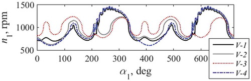
The curves of the input engine speeds have been shown in .
Figure 15. The curves of the input engine speeds according to .
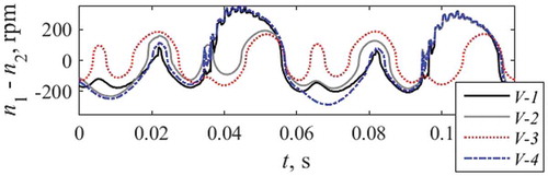
Following the performed calculations, differences in the angular, hence rotational speeds were obtained (). By calculating δ for both masses and comparing them, we may determine the percentage differences. For individual variants they were:
V-1 – 66.4 % at Tmean = 95.4 Nm and ωmean = 100.3 rad/s,
V-2 – 74.6 % at Tmean = 35.8 Nm and ωmean = 103.9 rad/s
V-3 – 65.4 %, at Tmean = 73.4 Nm and ωmean = 102.1 rad/s,
V-4 – 64.2 % at Tmean = 55.0 Nm and ωmean = 102.6 rad/s.
Figure 16. Differences in the speeds of the primary and secondary masses according to .
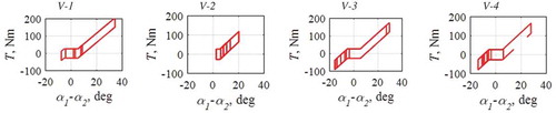
Beside the speeds, operating ranges of the DMF for each analysed variants were also determined ().
Figure 17. DMF operating range depending on the variant from .
5. Conclusions
As a result of the performed calculations, the applicability of the proposed mathematical model of operation of a dual mass flywheel was confirmed. Despite significant model simplification and the introduction of the indicated pressure curves along with the DMF characteristics as input data, the model sensitivity to small changes in the input parameters was confirmed. Additionally, the adequacy of the model was verified for different variants of engine related distortions i.e. misfires, cylinder blows–by or knock combustion.
Calculations were also performed for different configurations of the distortions in four consecutive cylinders. Based on the value of the engine irregularity coefficient, it was observed that the occurrence of extreme cases such as misfires or knock combustion determine the DMF operation. This is of particular significance for diesel engines that very often operate on the verge of knock combustion.
The model can be supplemented (as a replacement for the characteristics of the actual object) with calculations of the spring rigidity for different materials or damping parameters.
Acknowledgments
The research has been carried out within work no. S/WM/1/2018 realised at Bialystok University of Technology and financed from the funding allocated for science by the Ministry of Science and Higher Education.
Disclosure statement
No potential conflict of interest was reported by the author.
Additional information
Funding
References
- A. Albers, Advanced development of Dual Mass Flywheel (DMFW) design – Noise control for today’s automobiles, in 6th LuK–Symposium 1998, Germany.
- C. de Metsenaere, Fracture analysis of Dual Mass Flywheel arc springs, in DCT Rapporten: 2002.078, Technische Universiteit Eindhoven, Eindhoven, 2002.
- T. Khochare, Design development and comparative analysis of spring mass flywheel vs conventional flywheel for two-stroke engine, Int. J. Eng. Appl. Sci. Res. 4 (2015), pp. 1–11.
- S. More, P. Medankar, and M. Nagargoje, Design and development of dual mass flywheel system, Int. J. Innovative Res. Sci. Eng. Technol. 4(3) (2015), pp. 964–969. doi:10.15680/IJIRSET.2015.0403025
- U. Schaper, O. Sawodny, T. Mahl, and U. Blessing, Modeling and torque estimation of an automotive dual mass flywheel, in Proceedings of the American Control Conference (ACC 2009), 10-12 June, St. Louis, USA, 2009, pp. 1207–1212. doi:10.1109/ACC.2009.5160136.
- M. Sidorowicz and D. Szpica, The Dual–Mass Flywheel – Design and analysis, Modelowanie inzynierskie. 15(46) (2013), pp. 103–109 (in Polish)
- S. Theodossiades, M. Gnanakumar, H. Rahnejat, and P. Kelly, Effect of a Dual–Mass Flywheel on the impact–induced noise in vehicular powertrain systems, P. I. Mech. Eng. D.-J. Aut. 220(6) (2006), pp. 747–761. doi:10.1243/09544070jauto55
- A. Govinda and K. Annamalai, Design and analysis of arc springs used in dual mass flywheel, Int. J. Eng. Technol. Res. 2 (2014), pp. 35–41.
- I.A. Oday and J. Schlattmann, Vibration analysis of the friction clutch disc using finite element method, Adv. Mechanical Eng. Appl. 1 (2012), pp. 86–91.
- L. Wramner, Torsional vibrations in truck powertrains with dual mass flywheel having piecewise linear stiffness, in Proceedings of the 9th European Nonlinear Dynamics Conference (ENOC 2017), 25-30 June, Budapest, Hungary, 2017, 10 p.
- A. Walter, S. Brummund, and B. Merz, Estimation of the instantaneous engine torque for vehicles with dual mass flywheel, IFAC Proc. Vol. 40(10) (2007), pp. 1–8. doi:10.3182/20070820-3-US-2918.00024
- LuK Catalog, Schaeffler Automotive Aftermarket GmbH & Co. KG, Germany, 2012.
- J. Czaban and D. Szpica, The initial diagnostics of the dual–Mass flywheel in quasi–Static conditions, Combust. Engines. 3 (2013), pp. 643–646 ( CD-ROM (in Polish)).
- L. Chen, M.R. Deng, and Z.F. Jiang, Optimization method of performance parameters of dual mass flywheel, Trans. CSICE 30 (2012), pp. 277–283.
- L. Shengtian, Influences of a dual mass flywheel damper on idling vibration, Trans. Chin. Soc. Agric. Machinery 35 (2004), pp. 16–19.
- R. Zeng, Z.F. Jiang, and X. Wan, Frequency response analysis of damped dual mass flywheel, Appl. Mech. Mater. 742 (2015), pp. 271–274. doi:10.4028/www.scientific.net/AMM.724.271
- G. Zhao, Z. Jiang, and L. Chen, Linear analysis for performance of dual mass flywheel with centrifugal pendulum vibration absorbers system, Telekomnika. 11(5) (2013), pp. 2371–2376. doi:10.11591/telkomnika.v11i5.2462
- Q.H. Zu, Z.Y. Chen, W.K. Shi, Y. Mao, and Z.Y. Chen, Torsional vibration semiactive control of drivetrain based on magnetorheological fluid dual mass flywheel, Math. Probl. Eng. (2015) Article ID 608737, pp. 17 p. doi:10.1155/2015/608737
- Y. Zhengfeng, Z. Kunpeng, and L. Chunfang, Reliability analysis of the dual mass flywheel damping flange based on workbench, in Proceedings of the 3rd International Conference on Materials Engineering, Manufacturing Technology and Control (ICMEMTC 2016), 27-28 Fabruary, Taiyuan, China, 2016, pp. 1362–1368.
- A. Haris, E. Motato, S. Theodossiades, H. Rahnejat, P. Kelly, A. Vakakis, L.A. Bergman, and D.M. McFarland, A study on torsional vibration attenuation in automotive drivetrains using absorbers with smooth and non-smooth Nonlinearities, Appl. Math. Model. 46 (2017), pp. 674–690. doi:10.1016/j.apm.2016.09.030
- L. Chen, R. Zeng, and Z.F. Jiang, Nonlinear dynamical model of an automotive dual mass flywheel, Adv. Mech. Eng. 7 (6) (2015), pp. 1–11. doi:10.1177/1687814015589533.
- D. Szpica, Modeling of the action of a dual mass flywheel, in Proceedings of the 22nd International Conference. MECHANIKA-2017, 19 May, Birštonas, Lithuania, 2017, pp. 372–376.
- D. Chen, Y. Ma, W. Sun, X. Guo, and X. Shi, Research of design and vibration reduction of dual mass flywheel with arc helix spring, Proc. Int. Conf. Electron. Mechanical Eng. Inf. Technol. 11 (2011), pp. 2706–2079.
- D. Szpica and J. Czaban, Operational assessment of selected gasoline and LPG vapour injector dosage regularity, Mechanika. 20(5) (2014), pp. 480–488. doi:10.5755/j01.mech.20.5.7780
- A. Walter, U. Kiencke, and S. Jones, Misfire detection for vehicles with Dual Mass Flywheel (DMF), SAE Technical Paper 2007-01-3544, pp. 11. doi:10.4271/2007-01-3544.
- A. Walter, U. Kiencke, S. Jones, and T. Winkler, Anti-Jerk & Idle speed control with integrated sub-harmonic vibration compensation for vehicles with dual mass flywheels, SAE Int. J. Fuels Lubr. 1(1) (2009), pp. 1267–1276. doi:10.4271/2008-01-1737
- D.G. Dighole, R.S. Shelke, and S.N. Shelke, Design and development of dual mass flywheel for improving energy storage capability, Int. J. Science, Eng. Technol. Res. 4 (2015), pp. 2359–2364.
- K. Wituszynski, Angular Velocity and Torque as Carriers of Information about the State of the Internal Combustion Engine: A Theoretical-Experimental Study, LTN, Lublin, 1996 (in Polish).
- A. Iskra, Dynamics of Piston Internal Combustion Engines, Poznan University of Technology, Poznan, 1995 (in Polish).
- S. More, P. Medankar, and M. Nagargoje, Design and development of dual mass flywheel system, Int. J. Innovative Res. Science, Eng. Technol. 4(3) (2015), pp. 964–969. doi:10.15680/IJIRSET.2015.0403025
- T. Mahl and O. Sawodny, Modelling of an automotive dual mass flywheel, IFAC Proc. Vol. 43(18) (2010), pp. 517–523. doi:10.3182/20100913-3-US-2015.00069
- L.H.J. Romers, Automatic generation of combustion engine models using MatLab & Idle drive train model in MatLab/Simulink, DCT rapporten 2006.038, Technische Universiteit Eindhoven, Eindhoven, 2006, pp. 71.
- T. Kamiński, Evaluation of the quality of the spark ignition engine operating process using a fiber optic interference sensor, PhD thesis, Lublin University of Technology, Lublin, 2005 (in Polish).