Abstract
Size being limited for preparing standard specimens for mechanical tests, the weld poses problems to researchers and scientists in estimating the strength parameters and work-hardening coefficients. The integrity of the weld is difficult to probe into, particularly when the temperature of operation is much higher than the room temperature. The indentation creep test route is successfully tried by the authors to present a detailed commentary on the mechanical properties of a stainless steel weld at different test temperatures using a methodology whereby the creep test results are correlated to the compression test results and correlation equations developed. As the indentation creep tests can be carried out on a small-sized sample, the method enables one to carry out only this test to judge the mechanical properties of the welds.
1. Introduction
Metal joining process is an important production process wherein the joint that combines two parts plays a crucial and deciding part as it is expected to be as good as or even better than the adjoining parts in terms of parameters of strength. The weld, however, puts forward some challenges in the decision process as parameters of strength are likely to vary as the conditions of service vary in a given situation or application. This is due to the heterogeneity that is common in all kinds of welds. The as-cast structure will change due to external stimuli like temperature and stress that results in the variation of properties. A standard test specimen that exactly replicates the weld in question for tensile and creep tests can hardly be prepared. This situation has given way to evolve alternate methods of testing for small components/welds to probe into their properties. Indentation creep test is one such test evolved in the recent times that can depict many parameters of strength from tests out of a small-sized specimen.
AISI 316 stainless steel welds are the widely used welds nowadays – in the thermal/nuclear power generation sector wherein the integrity of the weld is of practical importance. Hence, these joints were selected for the indentation creep tests (also known as impression creep tests).
Indentation creep tests (also known by impression creep tests) have been successfully carried out by a number of investigators on different ferrous and non ferrous metals/alloys, polymers and composites (Li Citation2002; Lisin et al. Citation1990; Yang and Li Citation1995; Yang and Li Citation1997). In addition, micro-indentation studies are done and micro-indentation relaxation measurements are recorded for few selected materials (Mayo and Nix Citation1988; Shinozaki and Lu Citation1997). Conclusions drawn include steady state impressing (penetrating) velocity following power law function of the indenting stress, stress exponent values closely following those obtained under conventional creep, activation energy values obtained by plotting the logarithm of impressing velocity at the same indenting stress versus the reciprocal of temperature agreeing with that obtained from conventional creep testing (Kutty et al. Citation2010; Murthy and Sastry Citation1982; Kutty et al. Citation2012). However, indentation creep test results can be conveniently linked to the mechanical test results of a given material or its weld to create a database so that the former can take on the latter when material or weld has constraints in shape and size. This may have a wider utility in certain circumstances. Hence, an attempt is made here to correlate the results of two different tests.
2. Experimental procedure
Apparatus used for carrying out the impression creep test is of ‘Split Cage connected to Lever with Weights’ type where the split cage made out of superalloy Nimonic 90 (with Cr: 19%, Co: 17%, Ti: 2.5%, Al: 1.5%, balance Ni) is used (this will enable the investigator to get error-free results while experiments are conducted at high temperatures).
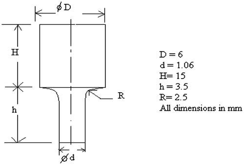
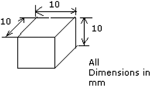
Sample in the form of cube with size 10 × 10 × 10 mm is mounted on the bottom of the cage for the test. The indenter is made out of tungsten carbide and its circular indenting surface is one mm in diameter. This is shown in Figure A. The set-up for the test is schematically shown in Figure B and the test specimen in Figure C.
Figure 1B. Indentation creep test set-up (schematic): (1) specimen, (2) indenter, (3) furnace/chamber of Test, (4) fixed frame of cage, (5) moving frame of the cage, (6) thermocouple, (7) vertical rod, (8) cooling coil, (9) LVDT, (10) argon gas cylinder, (11) balancing weight, (12) weights and (13) dashpot system.
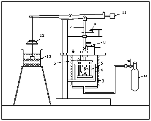
Depth of indentation at a constant stress over a period of long time is measured using linear variable differential transformer (LVDT) with the accuracy level of 1 micron. Temperature of the sample is maintained constant using a hollow cylindrical electric furnace in which the cage operates. The temperature of the furnace is controlled within the range of ±5 °C using an electronic stabilizer. Care is taken to see that the tip of the thermocouple is kept near the sample to measure the temperature. Water cooling was introduced over the vertical rod leading to the cage when samples were tested at higher temperature. The cage was shrouded with flowing argon gas when testing was carried out at higher temperature to prevent the oxidation of the indenter. The whole set-up is isolated from other working instruments and machines to minimize the vibrations in the system.
The data acquisition unit of the computer stores the indenter displacement values occurred over the time in a given test that can be retrieved. The displacement values are to be divided by the indenter diameter to get the strain values. The slope of the strain–time curve at any point gives the creep rate prevailing at that instant. The slope of the curve at the secondary creep stage gives the steady state creep rate (SSCR) value.
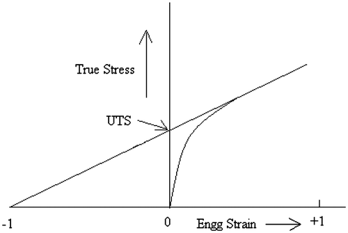
DARTEC make compression testing machine was used to test the AISI 316L samples under compression. The machine used was servo-hydraulic type with a capacity to load up to 8 tonnes. Strain rates ranging from 10e−3 to 10e+3 could be chosen for the tests on the machine. For the present tests, a constant strain rate of 10e−2 mm/mm/s was chosen. The machine can be used to test the samples in the temperature range of 30–1000 °C. In this study, the temperature range chosen was 30–700 °C. Temperature of the furnace was controlled by THOMSON make temperature controller with an accuracy level of ±2 °C. Load vis-à-vis stroke values are recorded in a computer that can readily show/print load vs. stroke curve after the completion of a test. The stress–strain curve can be drawn subsequently using the available data. By adopting Considere’s construction, ultimate tensile strength (UTS) values of the samples could be obtained. Considere’s construction is illustrated in Figure , which is self explanatory.
Table summarizes the scheme of ageing of samples and the methodology which was adopted for conducting indentation and compression tests.
Table 1. Scheme of ageing and testing for AISI 316L weld metal samples.
3. Results
Indentation creep tests results were taken into the Excel sheet to obtain the creep curves, and from the slope of the secondary stage of this curve, SSCRs were obtained. Tables and present the SSCRs for two different loads.
Table 2. SSCRs for AISI 316L weld metal samples – 10 kg load test (10 kg load is equivalent to 550 MPa).
Table 3. SSCRs for AISI 316L weld metal samples – 12 kg load test (12 kg load is equivalent to 660 MPa).
UTS values obtained by conducting compression tests are presented in Table .
Table 4. Ultimate strength values for AISI 316L weld metal samples.
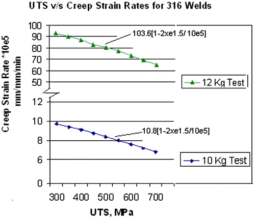
The UTS values mentioned in Table are based on Considere’s method which is explained in the previous section. The graphs presented in the Figure show the relation between creep rate and UTS of the material.
4. Discussion
Curves shown in Figure are plotted for the creep strain rates at two different stress levels, one corresponding to load of 10 kg and the other to load of 12 kg. It is found that relation in both of the cases falls into the equation of the type:(1)
where Y is the SSCR and x is the UTS of the material, A, B and n are constants. The constant n can be called creep strength coefficient. The value of n is 1.5, B is 2 * 10e−5 in both the cases whereas A takes the value of 10.8 for 10 kg load test and 103.6 for 12 kg load test. The equation of the type mentioned above could be quite useful to predict the integrity of the material in a small region like weldments. By carrying out indentation creep tests, the local variation of tensile properties in a complex material system with a micro-structural gradient like a weldment can be assessed, particularly at higher temperatures. In a practical condition, the situation may be more complex as microstructural variation is superimposed by the thermal gradient. The exercise would help to predict the weakest spot of the component or material system under a complex situation.
In order to observe the variations in the values of strain exponent (η) and stress exponent (n) for the samples, bar charts were erected based on the present work as shown in Figure . It is seen that strain exponent values remain almost constant, while stress exponent values vary substantially from one sample to other.
Figure 4. Stress exponent vis-a-vis strain exponent values for 316L samples: correlation at room temperature. [Sample Type 1: un-aged sample of weld. Sample Type 2: weld aged at 400 °C for 1000 h. Sample Type 3: weld aged at 400 °C for 1500 h. Sample Type 4: weld aged at 400 °C for 2000 h].
![Figure 4. Stress exponent vis-a-vis strain exponent values for 316L samples: correlation at room temperature. [Sample Type 1: un-aged sample of weld. Sample Type 2: weld aged at 400 °C for 1000 h. Sample Type 3: weld aged at 400 °C for 1500 h. Sample Type 4: weld aged at 400 °C for 2000 h].](/cms/asset/37d49214-138c-4883-8510-3047d00df263/tmec_a_1093214_f0004_oc.gif)
This suggests that stress exponent values derived from the creep tests are more sensitive to micro-structural variation resulting from the processing like ageing treatment compared to the strain exponent values derived from tensile/compression testing.
For the cylindrical indenter used in the indentation creep test, the indent size at a given moment is constant, and hence, the stress is proportional to the load. This makes way for the choice of stress for a given experiment and relates easily the creep data collected to the required property parameters. A larger load will induce a higher strain rate, and a range of load for the test is specified considering the yield stress and ultimate strength value of the test material (Sastry Citation2005; Udayaprasanna Citation2009). A higher testing temperature also will enhance the creep rate, and tests conducted at different temperatures will enable the investigator to find the stress exponent values (Mahmudi and Geranmayeh Citation2010). While ageing temperature and ageing time at different combinations are likely to modify the structure of a given alloy or its weld, the creep strains will be varied for the specimens that are tested for these materials after a given ageing cycle. Generally, ageing treatment time is large compared to the test period, and hence, modifications are not expected during the course of the test, even if the test is being carried out at a higher temperature.
5. Conclusion
Integrity of a given weld is most often difficult to assess, because of the limitation of the weld size. It is particularly difficult to judge the local variation of properties in the weld. The indentation creep test results obtained on welds along with relevant correlation equations can help the designer to assess the weld quality and determine its strength to a large extent.
In the present work, creep strain rate values are correlated with the UTS values for the AISI 316L weld samples and it has been found that there is a well-matched relationship between the two. Correlation equations are arrived at for two stress levels. There is scope for standardization of this method, given a wider database available for creep strains. It can also be concluded that the method provides an easy path for correlation considering the fact that indentation creep tests are short-duration tests compared to conventional creep tests and test parameters can be controlled within specified limits. Moreover, indentation creep test is like a nondestructive test, and hence, the test can serve as inspection method for welds or general materials.
Disclosure statement
No potential conflict of interest was reported by the authors.
Additional information
Notes on contributors
H. Udaya Prasanna
Prof. Rajendra K. Udupa is a professor in the department of Metallurgical and Materials Engineering at National Institute of Technology Karnataka (NITK), Mangalore, India. He has obtained his ME and PhD from the department of Metallurgy, Indian Institute of Science, Bangalore. He is teaching in the department of Metallurgical and Materials Engineering at NITK since 1982, guided 3 doctoral theses, executed 5 funded projects and has published 40 technical papers at international level. His research interests include indentation creep of stainless steel and other materials, melting and refining of steel, electro-slag refining, casting defects, welding failures, fractography, metallography and gravity die casting.
K. Rajendra Udupa
Prof. Udaya Prasanna H. is a professor in the department of Mechanical Engineering, at Visvesvaraya Technological University-affiliated Anjuman Institute of Technology and Management, Bhatkal, Karnataka, India, teaching there since 1990. He is ME from the department of Mechanical Engineering, Indian Institute of Science and PhD from the department of Metallurgical and Materials Engineering, NITK, Mangalore. He is guiding 2 students for PhD and has 9 technical papers (international level) to his credit. His research interests include indentation creep of stainless steels and alloy steels, creep of tin–lead solders and lead-free alloys, wear of steels and composites, metal casting science and technology, mechanical metallurgy and failure of materials.
References
- Kutty, T. R. G., Arunkumar, and H.S. Kamath. 2010. “Determination of Activation Parameters Using Impression Creep Data.” Transactions of the Indian Institute of Metals 63: 443–447.10.1007/s12666-010-0061-6
- Kutty, T. R. G., Santu Kaity, C. B. Basak, Arunkumar, and R. P. Singh. 2012. “Creep Behaviour of U–6%Zr Alloy by Impression Creep Technique.” Nuclear Engineering and Design 250: 125–133.10.1016/j.nucengdes.2012.05.013
- Li, J. C. M. 2002. “Impression Creep and Other Localised Tests.” Material Science and Engineering – A 322: 23–42.10.1016/S0921-5093(01)01116-9
- Lisin, M. A., I. D. Choi, D. K. Matlock, and D. L. Olson. 1990. “A Composite Modelling Analysis of Impression Creep Testing on Heterogeneous Materials.” International Welding Journal 69: 159s–165s.
- Mahmudi, R., and A. R. Geranmayeh. 2010. “A Comparative Study of Temperature Creep in Lead-free Tin Based Solder Alloys.” International Journal of Materials Research 101: 271–278.10.3139/146.110266
- Mayo, M. J., and W. D. Nix. 1988. “A Micro-indentation Study of Super-plasticity in Pb, Sn and Sn-38wt% Pb.” Acta Metallurgica 36: 2183–2192.10.1016/0001-6160(88)90319-7
- Murthy, G. S., and D. H. Sastry. 1982. “Impression Creep of Zinc and the Rate Controlling Dislocation Mechanism of Plastic Flow at High Temperature.” Physica Status Solidi – A 70 (1): 63–71.10.1002/(ISSN)1521-396X
- Sastry, D. H. 2005. “Impression Creep Technique—An Overview.” Journal of Materials Science and Engineering – A 409: 67–75.10.1016/j.msea.2005.05.110
- Shinozaki, D. M., and Y. Lu. 1997. “Micro-indentation Relaxation Measurements in Polymer Thin Film.” Journal of Electronic Materials 26: 852–858.10.1007/s11664-997-0262-x
- Udayaprasanna, H. 2009. “Studies on Indentation Creep Behaviour: Aged Weldments of 316L Type Stainless Steel and Cast Tin–Lead Alloys.” PhD thesis, Department of Metallurgical and Materials Engineering, N.I.T.K., Mangalore, India.
- Yang, F. Q., and J. C. M. Li. 1995. “Impression Creep Test of 63Sn-37Pb Eutectic Alloy.” Materials Science and Engineering: A 201: 40–49.10.1016/0921-5093(95)09762-7
- Yang, F. Q., and J. C. M. Li. 1997. “Newtonian Viscosity Measured by Impression Test.” Journal of Non-Crystalline Solids 212: 126–135.10.1016/S0022-3093(96)00656-4

