Abstract
Experiments have been performed to investigate the characteristics of the flow-induced vibration response of pivoted rigid circular cylinders with attached wake splitter-plates. Motion of the cylinder was constrained to the plane normal to the flow direction and the response characteristics were assessed in regard to the peak angular excursion of the cylinder and the frequency of the cylinder oscillation. Across the range of splitter-plate lengths tested 0.5 < l/D ≤ 3.0, large angular excursions of a galloping-type response were observed together with reduction in the oscillation frequency of the cylinder with increased splitter-plate length.
Introduction
For a bluff body of circular cylinder geometry in crossflow at Reynolds numbers (Re) greater than around Re ~ 40 the pair of free-shear layers of the near-wake – that have their origin in the flow detachment locations at the cylinder surface – become inherently unstable (Sumer and Fredsoe Citation1999). Due to this instability, they interact which each other, alternately rolling up and forming large scale vortices, which are subsequently shed from the cylinder and convected downstream. As a consequence of the proximity of the region of vortex formation to the cylinder and the reduced localized pressures associated with the vortices, unsteady forces act on the cylinder. Under the right combination of structural and flow conditions, a significant vortex-excited vibration response of the cylinder can occur, known generally as vortex-induced vibration (VIV). The VIV phenomenon of circular cylinders in crossflows has been studied by numerous authors, including, for example, Khalak and Williamson (Citation1997, Citation1999), Govardhan and Williamson (Citation2000), Klamo, Leonard and Roshko (Citation2006), Willden and Graham (Citation2006), Blevins and Coughran (Citation2009). The majority of studies that address VIV of circular cylinders consider the classical case of vibration normal to the incident flow direction and with uniform vibration amplitude along the entire cylinder span.
For a pivoted circular cylinder, the flow-structure interaction, unlike the general two-dimensionality of the uniform spanwise amplitude case, is inherently a three-dimensional problem – significant differences do exist between the two cases. The vortex shedding frequency and thus the timing of fluid forcing at different sections along the span of pivoted cylinders is not necessarily consistent. Distinct change in the predominant vortex shedding frequency along the span of pivoted circular cylinders has been found to occur (Balasubramanian et al. Citation2000). In close proximity to the cylinder pivot, the vortex shedding occurred primarily at the Strouhal frequency and, along the majority of the span, shedding frequency was controlled by the cylinder oscillation frequency during the VIV synchronization region. In addition to the predominant shedding frequency, the mode of vortex shedding along the pivoted cylinder span has been found to differ between the various VIV response branches (Flemming and Williamson Citation2005). For example, 2S and 2P modes where observed along the entire span of a pivoted circular cylinder during part of the initial and the entirety of the lower VIV response branches, respectively, while a 2S-2P hybrid mode was seen to occur for the larger vibrations of the initial response branch. The potential for hybrid vortex shedding modes to occur along the span is a clear indication of the impossibility of completely predicting the VIV behaviour of pivoted cylinders from knowledge of the VIV responses of uniform amplitude cylinders in uniform crossflows.
It is well established that while the circular cylinder is susceptible to VIV, it cannot be excited by the galloping phenomenon, which is characterised by large near linearly increasing vibration amplitudes as the crossflow velocity, or more precisely, the reduced velocity Ur, defined as Ur = U/(fnD), increases; where U is the free-stream velocity, fn is the natural frequency of the body in quiescent fluid and D is the characteristic dimension of the body (for details regarding the fundamentals of the galloping phenomenon, the reader is referred to the following: Blevins Citation1990; Païdoussis, Price and deLangre Citation2010). For the galloping phenomenon to occur (i) a body must present an altered cross section to the flow at non-zero angles-of-attack (Blevins Citation1990) and, in addition, (ii) there must be present an appreciable afterbody i.e. a significant portion of the body downstream of the locations of the flow separation points. The afterbody serves two purposes: firstly, it prevents the immediate interaction of the shear layers, postponing it to a location farther downstream of the separation points; and secondly, it provides the necessary surfaces for the pressure differential that develops across the body to act on and thus drive the body motion. Owing to its uniform geometry, both requirements (i) and (ii) above cannot be satisfied in the case of the circular cylinder. Thus, while the circular cylinder is potentially unstable in terms of a vortex-excited response (across a particular reduced velocity range) it is entirely stable in regard to the galloping phenomenon; provided no modification to the overall shape of the cylinder cross section is made or occurs as a consequence of environmental effects e.g. piggybacked cylinder arrangements, commonplace in the oil and gas industry, are susceptible to galloping as are, as an aero-elastic example, above-ground power cables when ice formations adhering to the cable surface change the effective shape of the cable cross section.
One well-established method of addressing the VIV susceptibility of the circular cylinder has been the use of thin wake splitter plates in the near-wake region of the cylinder. The splitter-plate exerts passive control on the dynamics of the near wake (Kwon and Choi Citation1996; Akilli, Sahin and Filiz Tumen Citation2005; Tiwari et al. Citation2005) modifying the wake flow in such a manner that VIV suppression is possible. Owing to the presence of the wake splitter-plate, the rolling up of the shear layers is postponed and the subsequent formation of the large-scale vortices of the near wake is forced to occur at locations farther downstream (Apelt, West and Szewczyk Citation1973; Anderson and Szewczyk Citation1997), thus mitigating the vortex-excitation of the cylinder. In spite of its capacity to suppress VIV, it is interesting to note that the presence of a fixed wake splitter-plate has been found under the right conditions to cause the circular cylinder to be prone to a galloping-type response (Kawai Citation1990; Nakamura, Hirata and Kashima Citation1994; Assi, Bearman and Kitney Citation2009; Stappenbelt Citation2010). Thus, there is the potential that in endeavouring to mitigate VIV of the circular cylinder through use of fixed wake splitter-plates, one may cause the system to become susceptible to the potentially even more destructive larger-amplitude vibration responses typically characteristic of the galloping phenomenon.
The typical case studied for the effects of wake splitter-plates on the flow-induced vibration (FIV) response of circular cylinders is the case of the elastically mounted cylinder moving with uniform amplitude along its entire span (length) – not cylinders pivoted about one end. Studies have been made into the VIV behaviour of the pivoted bare (i.e. no splitter-plate) circular cylinder, that by definition has non-uniform spanwise vibration amplitudes (see e.g. Balasubramanian et al. Citation2000; Fleming and Williamson Citation2005; Voorhees et al. Citation2008; Kheirkhah, Yarusevych and Narasimhan Citation2012). However, to the present authors’ knowledge, little, if any, studies exist that have investigated the vibration response of the pivoted rigid circular cylinder with attached wake splitter-plate.
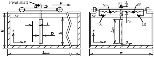
This paper reports on experiment outcomes for the galloping-type vibration response of pivoted rigid circular cylinders with 1-degree-of-freedom – whereby the cylinder is constrained to pivot about one end and swing only in the plane normal to the incident flow direction (i.e. the y–z plane, see Figure ) – and rigidly attached wake splitter-plates in water cross flow. The response parameters of interest were the peak angular excursion θ and the oscillation frequency f of the cylinder during the observed galloping-type responses. For a constant cylinder diameter and aspect ratio L/D, the effect of splitter-plate length l (measured in the streamwise direction) on the nature of the galloping-type response for the pivoted circular cylinder with fixed splitter-plate spanning almost the entire cylinder length was investigated.
Experiment apparatus and methodology
The experiments were conducted at the University of Wollongong SMART Building wavetank facility. The wavetank is a free-surface tank with water as the working fluid and dimensions of length Ltank = 25 m, width w = 1 m and overall height H ~ 1 m (the coordinate conventions corresponding to the tank length, width and height, respectively, are assumed the x-, z- and y-directions). Water depth h was maintained at h = 0.95 m throughout all the experiments. During the experiments, the water in the tank was still and cross flow velocity relative to the circular cylinder was achieved using a towing carriage powered by an electric motor running the full 25 m length of the tank. Thus, owing to the experimental arrangement and the allowance of sufficient intervals between successive tests, the turbulence levels of the fluid ‘upstream’ of the cylinder during the experiments was negligible. To constrain the cylinder motion to the plane normal to the relative flow direction, the cylinder was coupled to a shaft with the shaft axis aligned to the towing direction and running on a low-friction pillow block bearing pair mounted on the towing carriage. Thus, the test cylinder was pivoted about its upper end with the pivot point located approximately 0.20 m above the free-surface of the water. The carriage itself runs on rails secured to the upper members of the wavetank frame and with the existing set-up has a towing speed adjustable across the range 0 m/s < V < 1.4 m/s, with estimated speed control accuracy of ±0.05 m/s. Figure depicts the key features of the experiment arrangement including notation.
Cylinder and splitter-plates
The circular cylinder consisted of a smooth hollow PVC tube of outer diameter D = 0.044 m and overall length Lcyl = 0.82 m as the main part of the test specimen. Thus, the aspect ratio of the PVC tube section was Lcyl/D = 18.6. A hollow aluminium tube of outer diameter d = 0.025 m was inserted 0.10 m into the upper end of the PVC tube and the two tubes fitted together by means of solid watertight rubber grommets. The axial location of the tubes together with the rubber grommets was set by use of countersunk screws secured such that their heads aligned flush to the outer surface of the PVC tube. The aluminium tube was used in order to provide a stable, rigid joint at the interface of the test cylinder and the carriage-mounted pivot shaft. With the cylinder in the vertical position (i.e. cylinder axis parallel to the xy-plane), the gaps between the upper- and lower-ends of the PVC cylinder and the free-surface and wavetank bottom, respectively, were 2D and 1D. No end-plates were fitted to either the upper or lower ends of the cylinder.
All splitter-plates were made from 0.0018 m thick aluminium sheet and spanned almost the full length of the PVC tube such that the dimension of the splitter-plates aligned with the cylinder axis was slightly less than Lcyl in all cases (see Figure ); all splitter-plates were of the same length along the cylinder axis and in each case 0.055 m (1.25D) and 0.060 m (1.36D) short of the pivot-end and tip-end, respectively, of the PVC tube. A number of different splitter-plate lengths were employed: l/D = 0.0 (i.e. no splitter-plate, bare cylinder), 0.5, 1.0, 1.5, 2.0, 2.5 and 3.0, where l is the splitter-plate dimension parallel to the towing direction. Attachment of the splitter-plates to the PVC tube was achieved by cutting along the splitter-plate edge making contact with the PVC tube around 16 equispaced slots of approximately 15 mm length, each slot cut in the direction parallel to the l dimension. The tabs created by the cut slots were alternately bent in opposite directions, curved slightly to form a neat fit to the outer surface of the PVC tube and then glued and riveted to the PVC cylinder. In this way, the splitter-plates were non-rotating (N-R splitter-plates) about the cylinder axis. Careful alignment of the splitter-plate with the cylinder axis was ensured. It was intended that the splitter-plates would form a rigid extension of the circular cylinder. Accordingly, the lateral rigidity of the splitter-plates when attached to the cylinders using the method described above was checked and a high degree of stiffness was confirmed for all splitter-plate lengths. No appreciable lateral flexure of the splitter-plates was observed during the experiments.
Structural properties and experiment methodology
From free-decay tests in air of the bare cylinder (i.e. no splitter-plate), the applied damping of the experiment arrangement due to friction in the pillow block bearings of the cylinder pivot (assuming negligible damping effects due to the air) was determined. Calculation of the damping ratio ζ (the ratio of applied to critical damping) was performed using Equations (1) and (2).(1)
where n is the number of oscillation periods, p(t) is the peak oscillation at time t, p(t + nT) is the peak oscillation at time t + nT, and T is the oscillation period.(2)
Values for the damping ratio ranged between ζ ~ 0.005 and ζ ~ 0.0005 corresponding to cylinder angular excursions of and
, respectively (see Results section for definition of normalized angular excursion
). Thus, the degree of resistance to rotation offered by the pivot bearing arrangement was small. However, due to the bearing characteristics the level of damping was dependent on the magnitude of the cylinder oscillations and, as stated above, differed between large and small oscillations by an order of magnitude. Unavoidably, then, the larger magnitude oscillations of the experiments were more damped, though even under these conditions the applied damping level was still low i.e. ζ ~ 0.005. Therefore, in spite of the variation in applied damping, as a consequence of its dependence on the oscillation magnitude, all the experiments were conducted in their entirety under conditions of low levels of applied damping i.e. ζ ≤ 0.005.
For each experiment, extension springs were used to control the system stiffness. Two opposing spring sets of equal stiffness were mounted horizontally and in-plane with the y–z plane with one end attached to a collar fixed to the aluminium tube of the test cylinder and the other to the towing carriage (the spring sets are depicted as items ‘SP’ in Figure ). The offset rs of the spring sets (see Figure ) and associated carriage connection points from the cylinder pivot location P was changeable within a limited range in order to provide a degree of adjustability of the effective angular stiffness kθ (i.e. the rotational stiffness about the cylinder pivot) associated with each particular spring set used.
For n number of springs, each with equal stiffness k, the force exerted by the spring set is(3)
where d is the linear displacement of one end of the spring set, the other end fixed in place.
Thus, the total stiffness of the spring set ktotal is defined as(4)
Multiplying Equation (4) by the distance from the cylinder pivot to the spring set plane rs and then, assuming small angular motions i.e. sin θ ~ θ, relating spring displacement (at the spring ends fixed to the aluminium tube collar) to angular motion about the cylinder pivot gives the effective angular stiffness(5)
Further adjustment of kθ was achieved by changing to a spring set of different stiffness (i.e. different ktotal) and again varying the offset of the spring set from the pivot location within the range available.
Properties of the test cylinders with their respective splitter-plates attached are presented in Table . The parameters M* and I* are the moment ratio and inertia ratio, respectively. The natural frequencies fn-air corresponding to each splitter-plate cylinder without any applied stiffness (i.e. no spring sets installed) were determined by means of decay tests with the system oscillating freely in air.
Table 1. Structural properties of test cylinders with splitter-plates.
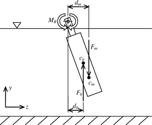
Figure portrays the experiment arrangement noting cb and cm to be the centre-of-buoyancy and centre-of-mass, respectively, each shown at arbitrary locations along the cylinder.
The moment ratio M* is considered herein to be the ratio of the moment acting about the cylinder pivot causing the cylinder to diverge from vertical alignment to the moment working to restore the cylinder to vertical alignment (i.e. cylinder axis parallel to the xy-plane) – exclusive of the externally applied system stiffness MR (due to the offset spring sets previously mentioned). For the orientation of the cylinder in this study (see Figure ) this corresponds, respectively, to the moment due to buoyancy (diverging moment) and the moment associated with the body mass (restoring moment). Hence,(6)
For all the splitter-plates tested, the moment ratio was maintained at M* = 1.69 ± 0.19 (see Table ).
The inertia ratio I* is the ratio of the mass moments of inertia about the cylinder pivot associated with the distribution of the cylinder mass Im and the fluid displaced by the cylinder If.(7)
The experiment outcomes presented in the Results section are plotted as a function of reduced velocity Ur and for each splitter-plate the vibration response was investigated across the reduced velocity range 2 < Ur < ~28. To achieve this range of reduced velocities, various combinations of the spring set stiffness, offset of the spring sets from the cylinder pivot location and the towing speed of the carriage were employed. That is, for a given spring set and offset rs of the spring set plane from the pivot location, experiments were made that varied the towing speed within the range 0.05 m/s < V < ~0.45 m/s (Therefore, based on the PVC cylinder diameter, and assuming a water temperature of 20 °C, all the experiments were conducted within the Reynolds number range 2 × 10³ < Re < 2 × 10⁴ i.e. within the subcritical range). This was followed by selectively altering the spring set pivot offset – and thus altering the natural frequency fn of the system – and repeating the tests across the towing speed range. Once the limits of spring set pivot offset had been reached a new spring set with different stiffness was installed to the test apparatus and the process repeated until testing across the entire desired range of reduced velocities was completed.
The natural frequency of the bare cylinder in water fnb corresponding to each of the various spring set/spring set offset combinations used was measured. Throughout, calculation of reduced velocity (for the bare cylinder and all splitter-plate cases) is based on these bare cylinder natural frequencies using the value of fnb that applies to the spring set-up in each particular case.
Data collection and processing
The cylinder vibration response data were measured and recorded using laser displacement sensors coupled to a laptop computer mounted to the towing carriage and running data recording software. The laser sensors were low power <1 mW at wavelength 670 nm (red) with a working range between 50 and 200 mm from the sensor face. The manufacturer claimed measuring rate and resolution are 750 Hz and 0.10 mm, respectively. Tests consisting of randomized motion across the middle 50 mm of the working range of the sensors found the RMS difference between the measurements of the two sensors employed to be less than 0.20 mm. All experiment data were recorded at 100 Hz. During the experiments, the two sensors were used simultaneously to provide a means of fault checking the sensors, whereby notably dissimilar sensor data would indicate a fault. The laser sensors were fixed in place on the towing carriage with their beams parallel to both the z-axis and the yz-plane (see Figure , items ‘LS’ denote the laser sensors). The sensors measured the ‘apparent’ linear motion of the cylinder along the path of the laser sensor beams and not, therefore, the angular excursion directly, as desired for results presentation. Hence, taking account of the geometry of the system, post-processing of the data obtained was performed converting the ‘apparent’ linear motion to angular motion of the cylinder about the cylinder pivot. From this linear-to-angular converted data, in each experiment run, the peak angular excursion θ of the pivoted cylinder was determined through averaging the top (largest) 10% of the vibration response data and vibration frequency f was obtained based on the average zero-crossing period of cylinder oscillation. In the presented results, both the θ and f data are the averages of θ and f obtained with the two sensors.
Results
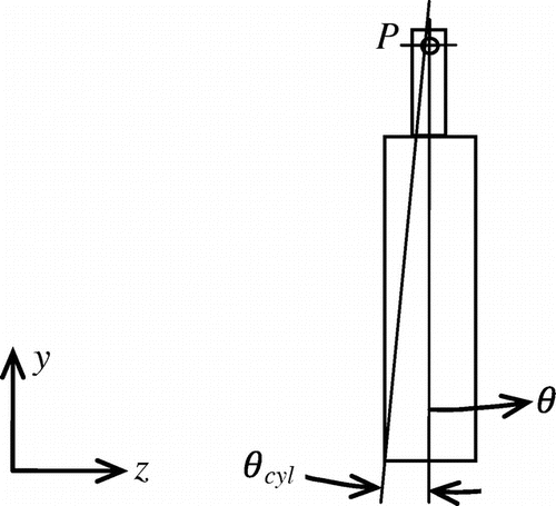
Throughout the Results and Discussion Sections, the angular excursion of the pivoted cylinder is defined in terms of a normalized angular excursion θ* = θ/θcyl, where θ is the angular orientation of the cylinder axis from vertical and the cylinder angle, θcyl is the angle between the cylinder axis and a line taken from the pivot location P to a point on the circumference at the end of the cylinder farthest from the pivot (see Figure ). The cylinder angle θcyl was employed as the base unit for normalizing the angular excursion in order to express the cylinder motion in regard to the cylinder aspect ratio.
Cylinder without splitter-plate
The vibration and frequency response outcomes for the bare pivoted cylinder case (i.e. without splitter-plate) are presented in Figures and . The experiments to obtain these results were performed to provide a base case against which the responses of the cylinders with the various splitter-plates attached could be compared.
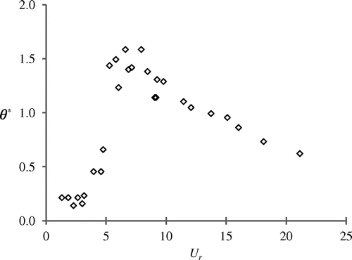
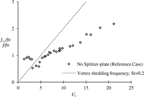
It is apparent from Figure that qualitatively the normalized angular excursion θ* (i.e. the pivoted cylinder equivalent to amplitude of the translating cylinder) vs. Ur relationship for the no splitter-plate case exhibits the features typically associated with VIV of circular cylinders. That is, the results exhibit negligible vibration prior to the start of synchronization at around Ur = 5, oscillations of significant magnitude across the Ur range that corresponds to synchronization (in this case, approximately 5 ≤ Ur ≤ 15) and, finally, also exhibit what appears to be a trend towards desynchronization occurring at sufficiently high Ur. Likewise, the frequency response results for the pivoted cylinder without splitter-plate shown in Figure also exhibit characteristics typical of VIV for circular cylinders. Following the observations of Balasubramanian et al. (Citation2000) regarding the shedding frequency from the base of pivoted circular cylinders (see Introduction Section), in Figure a Strouhal line using a Strouhal number of St = 0.20 is included to indicate the predominant frequency fvs at which vortex shedding would be expected to occur from the section of span adjacent to the cylinder pivot if this region, instead of being above the free surface, was also submerged in the water cross flow and of equal diameter to the main test cylinder.
Cylinders with splitter-plates
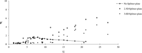
With the addition of N-R splitter-plates to the cylinder, no longer were the vibration response characteristics in accord with VIV. Instead, the oscillations now exhibited features characteristic of a galloping-type response. The experimental outcomes for the pivoted circular cylinder with attached N-R splitter-plates of various lengths are presented in Figures and these contrast sharply against the behaviour of the cylinder with no splitter-plate (also included in Figures for comparison).
Figure 6. Vibration responses of pivoted cylinder with splitter-plates l = 0.5D, l = 1.0D, l = 1.5D and l = 2.0D.
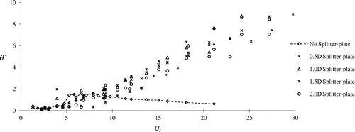
Figure 8. Frequency responses of pivoted cylinder with splitter-plates of various lengths. (Note: f/fn axis truncated at f/fn = 1.5 to aid clarity. Thus, a number of the no splitter-plate data points only are absent).
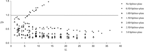
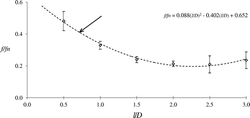
Figure 9. Average oscillation frequency of each splitter-plate through-out Ur > 10. Note: Upper and lower dashes are offset by 1 standard deviation.
In all cylinder with N-R splitter-plate cases, initiation of vibration of significant magnitude began within the region 3 ≤ Ur ≤ 12 (see Figures and ). Up to the point where this initiation Ur (the critical reduced-velocity Ur,crit) was reached, the magnitude of the oscillations for each splitter-plate case was small (see Figures and ) without any clear relationship between the oscillation frequency f, which itself was somewhat variable at pre-critical Ur values and Ur (see Figure ).
Figure 10. Linear trend-line fits to angular excursion of pivoted circular cylinder with attached N-R splitter-plates l = 0.5D, l = 1.0D, l = 1.5D and l = 2.0D.

However, as Figure shows, in spite of the inconsistency in frequency, the cylinder oscillations throughout the lower Ur region (i.e. less than the critical Ur) for each splitter-plate occurred generally at marginally higher frequency than the near-constant frequency exhibited throughout the region of larger Ur within which large-amplitude responses occurred. For example, in the case of l = 0.5D, the oscillation frequency reached a maximum of f/fn 0.6 in the range Ur < 3. Thereafter it steadied at around f/fn = 0.5 for Ur ≥ 6 and remained close to this value until Ur
20 whereupon the frequency began to reduce slightly, ultimately reducing to f/fn
0.4 at the highest reduced velocity of the experiment. All other N-R splitter-plates followed a similar trend, albeit at different f/fn values. In addition to the evident similarity for all N-R splitter-plates in the shape of the frequency responses across the experiment Ur range, Figure also shows a trend towards reduction in the relative oscillation frequency f/fn with increase in splitter-plate length. However, this did not occur without limit and a minimum of approximately f/fn
0.2 was apparent, as shown more clearly in Figure which plots for each N-R splitter-plate case the average of the oscillation frequency, averaged over the range Ur > 10.
Continual growth in the magnitude of the sustained large-amplitude vibration responses with increased Ur occurring in a roughly linear manner was observed for the splitter-plates in the range 0.5 ≤ l/D ≤ 2.0. Figure shows this ongoing growth in the vibration magnitude that followed on from its initiation at the critical Ur of each splitter-plate case. Unlike the shorter N-R splitter-plates, the magnitude of the vibration responses of the two longest N-R splitter-plates tested (i.e. l = 2.5D and l = 3.0D) was inconsistent and irregular, most noticeably in the case of l = 3.0D, as Figure shows. There is for each of these two longest N-R splitter-plates considerable scatter in the data and, therefore, a trend away from the more linear relationship between the oscillation magnitude and Ur was observed to exist for the shorter N-R splitter-plates tested. In addition, when compared to all the shorter N-R splitter-plates, the magnitude of oscillation in the case of the longest N-R splitter-plate tested (l = 3.0D) was substantially less at any given Ur (see Figure ).
Discussion
The results of the experiments highlight a clear distinction between the FIV response of the pivoted circular cylinder with (i.e. galloping) and without (i.e. VIV) attached N-R splitter-plates. This is as expected and is seen to occur in similar cases reported in the literature. However, these cases are usually concerned with the translating (uniform amplitude) circular cylinder and not for the pivoted cylinder case.
As stated earlier, the VIV response results for the bare pivoted cylinder experiment exhibit characteristics typical of circular cylinders undergoing VIV. Looking at the results in more detail, the angular excursion (see Figure ) displays an initial branch (Ur < ~5), a lower branch (Ur > ~8) and, to a small extent, what appears to be an upper branch (~5 < Ur < ~8) (however, no study was made of the wake modes during the present experiments and therefore whether transition in the vortex wake mode occurred, which is a characteristic of transition between initial to upper response branches, thus making the apparent upper branch a ‘true’ upper branch is unknown). Also, the synchronization region begins at Ur ~ 5. Thus, in regard to the shape of the response plot of pivoted circular cylinders, there is general agreement between the present results and, for example, those of Flemming and Williamson (Citation2005) obtained in water cross flow at slightly lower Re than the present experiments (although still within the subcritical range). However, it is noted that in the present experiment the peak of the upper branch, relative to the lower branch, is significantly less than for the I* = 1.03 case of Flemming and Williamson, where a notable upper branch was observed to occur (the value of M* corresponding to their I* = 1.03 test is not given). The general shape of the vibration response of the present work can also be seen, together with similar Ur at the onset of VIV synchronization, in the pivoted cylinder VIV study of Kheirkhah, Yarusevych, and Narasimhan (Citation2012).
In the 2DOF study of Flemming and Williamson (Citation2005), the upper (transverse) response branch just mentioned coincided with the occurrence of significant streamwise motion. Outside the Ur range, corresponding to the upper branch of the transverse response, the streamwise motions were relatively small. Thus, the large transverse oscillations of the upper response branch appeared to be brought about by wake modification associated with the significant streamwise vibrations of the cylinder enhancing the fluid forcing in the transverse direction. Clearly then, this limits comparison between the present work and the results of Flemming and Williamson to reduced velocities outside of the Ur range corresponding to the upper response branch of their results and is thought to provide some explanation for the differences in the magnitudes of the upper branch peaks. In regard to the cylinder oscillation frequency, there is good agreement between the shape of the frequency responses for the pivoted cylinder in the present work (see Figure ) and the outcomes of the 2DOF study of Flemming and Williamson with the exception of the two-step changes in the cylinder frequency response, and lower frequency between these two points, associated with the onset and outset of the upper (transverse) response branch of their experiment. That is, the frequency responses are similar at all Ur values, where the streamwise oscillations in the experiment of Flemming and Williamson were small to negligible.
Hence, the pivoted bare cylinder (i.e. no splitter-plate) experiments displayed VIV response behaviour generally in accord with the results of other pivoted circular cylinder studies available in the literature.
Attachment of wake N-R splitter-plates altered the vibration response behaviour of the pivoted circular cylinder, causing it to be of the galloping-type. The modification to the cylinder by addition of the attached N-R splitter-plates made the galloping-type response is possible due to the cylinder/splitter-plate synthesis causing the effective cross section to satisfy the criteria mentioned in the Introduction: (i) a body must present an altered cross section to the flow at non-zero angles-of-attack, and (ii) there must be present an appreciable afterbody. The mass properties of the pivoted cylinder were relatively low (see Table ). Additionally, the low friction characteristic of the cylinder pivot bearings ensured all experiments were conducted under conditions of low applied damping. As a consequence of the combined effects of the low values for the mass properties and the low level of applied damping, one would expect for the pivoted cylinder with N-R splitter-plates the onset of the galloping-type response to have occurred at relatively small Ur. Indeed, this was consistently found to be the case for the splitter-plates tested and in all cases the onset Ur occurred relatively close to the Ur corresponding to the onset of VIV synchronization (see Table and Figure ), as is typically the case for bodies in water cross-flow (Parkinson Citation1989).
Table 2. Galloping onset-reduced-velocity (Ur-critical) for cylinders with splitter-plates.
The onset-reduced velocity increased with increasing the splitter-plate length, reaching for the longest N-R splitter-plate case (i.e. l = 3.0D) Ur-critical = 13.5 – slightly greater than double the VIV synchronization Ur. The increase in the onset-reduced velocity with splitter-plate length was presumed to be attributed to change in the nature of the fluid/structure interaction causing significant levels of fluid damping to act on the system throughout the lower Ur region below Ur-critical in each splitter-plate case. Also, changes in the nature of the fluid/structure interaction due to increased splitter-plate length may be causative in regard to the irregularity of the growth trend (i.e. the significant degree of data scatter) for the two longest splitter-plate cases, as mentioned previously. However, confirmation of the above hypotheses was not possible within the scope of the present experiments (lack of access to necessary experiment equipment).
One final point is made in regard to the distribution of the angular excursion data for the pivoted circular cylinder with attached N-R splitter-plates. Linear trend line fits (Lin. TL) shown in Figure for the angular excursion data corresponding to the four shortest N-R splitter-plates tested indicate that the apparent slope of θ* vs. Ur and the magnitude of θ* at a given Ur are expected to be greatest when a splitter-plate within the range 1.0 ≤ l/D ≤ 1.5 is employed. Of course, the significant degree of scatter present in the data of Figure imposes limitations on the accuracy of the linear trend line fits and necessitates consideration of how well the trend lines actually accord with the real behavioural trends of the system that underlie the data. However, whilst keeping this in mind, the linear trend line fits do at least suggest a particular N-R splitter-plate length exists at which the magnitude of the vibration (galloping) will be at its largest. This is perhaps unsurprising, given galloping cannot occur for the circular cylinder when l/D = 0.0 and the amplitude of galloping must approach zero as l/D → ∞.
Conclusion
Experiments have been conducted to study the FIV response of 1DOF pivoted rigid circular cylinders with attached wake N-R splitter-plates in water cross flow. Characteristics of the response examined were the peak angular excursion and the vibration frequency of the pivoted cylinder during steady-state (or at least, quasi-steady state) conditions. For the N-R splitter-plates tested across the range 0.5 ≤ l/D ≤ 2.0 large near linearly increasing magnitude of angular excursion of the cylinder was observed as reduced velocity increased above that corresponding to initiation of significant vibration of the cylinder. Thus, the vibration response of the pivoted cylinder with the N-R splitter-plates 0.5 ≤ l/D ≤ 2.0 was of the galloping-type and exhibited well-defined patterns of response behaviour.
While also of the galloping-type, unlike the shorter N-R splitter-plates, the magnitude of the vibration responses of the two longest N-R splitter-plates tested (i.e. l = 2.5D and l = 3.0D) was inconsistent and irregular, particularly in the case of the l = 3.0D N-R splitter-plate and of lower magnitude at a given reduced-velocity when compared to the shorter N-R splitter-plates. Across the range of N-R splitter-plate lengths tested, a relationship between the vibration frequency and splitter-plate length was observed with the frequency of cylinder oscillation reducing to a minimum at a N-R splitter-plate length of l = 2.5D. Finally, the oscillation frequency observed for each particular N-R splitter-plate length was relatively constant throughout the reduced velocity range above that corresponding to initiation of the galloping-type response i.e. Ur > Ur,crit. The results have implications for the N-R splitter-plate lengths that potentially represent the worst- and best-case scenarios, respectively, for pivoted rigid circular cylinder structures and future flow-energy extraction devices that may be based on the rigid pivoted cylinder.
Notes on contributors
Mr. Andrew Johnstone is a PhD candidate at the Faculty of Engineering and Information Sciences – School of Mechanical, Materials and Mechatronic Engineering, University of Wollongong, NSW, Australia. Since 2010, he has been involved in research into renewable energy technologies exploiting the energy sources of ocean waves and currents. His current research activities explore the flow-induced vibration of circular cylinders in cross-flows and the potential for such phenomena to be a means of extracting useful energy from naturally occurring flows. Away from his academic activities, he enjoys competition cycling, tennis, reading and time enjoying nature.
Dr. Brad Stappenbelt PhD, BEng(hons I), DipIT, GradCertEd, is a senior lecturer with the School of Mechanical, Materials and Mechatronics Engineering at the University of Wollongong. Brad obtained his PhD in Offshore Engineering from the University of Western Australia. His research interests include flow-structure interaction, floating system dynamics and ocean energy conversion systems.
Acknowledgements
The authors gratefully acknowledge the contribution of Mr. Matthew Lingard in the collection of experimental data utilized in the present paper.
Disclosure statement
No potential conflict of interest was reported by the authors.
References
- Akilli, H., B. Sahin, and N. Filiz Tumen. 2005. “Suppression of Vortex Shedding of Circular Cylinder in Shallow Water by a Splitter Plate.” Flow Measurement and Instrumentation 16 (4): 211–219.10.1016/j.flowmeasinst.2005.04.004
- Anderson, E. A., and A. A. Szewczyk. 1997. “Effects of a Splitter Plate on the Near Wake of a Circular Cylinder in 2 and 3-Dimensional Flow Configurations.” Experiments in Fluids 23 (2): 161–174.10.1007/s003480050098
- Apelt, C. J., G. S. West, and A. A. Szewczyk. 1973. “The Effects of Wake Splitter Plates on the Flow Past a Circular Cylinder in the Range 104 < R < 5 × 10⁴.” Journal of Fluid Mechanics 61 (01): 187–198.10.1017/S0022112073000649
- Assi, G. R. S., P. W. Bearman, and N. Kitney. 2009. “Low Drag Solutions for Suppressing Vortex-induced Vibration of Circular Cylinders.” Journal of Fluids and Structures 25 (4): 666–675.10.1016/j.jfluidstructs.2008.11.002
- Balasubramanian, S., R. A. Skop, F. L. Haan Jr., and A. A. Szewczyk. 2000. “Vortex-excited Vibrations of Uniform Pivoted Cylinders in Uniform and Shear Flow.” Journal of Fluids and Structures 14 (1): 65–85.10.1006/jfls.1999.0255
- Blevins, R. 1990. Flow-induced Vibration. New York: Van Nostrand Reinhold.
- Blevins, R. D., and C. S. Coughran. 2009. “Experimental Investigation of Vortex-induced Vibration in One and Two Dimensions with Variable Mass, Damping, and Reynolds Number.” Journal of Fluids Engineering – Transaction of the ASME 131 (10): 1012021–1012027.
- Flemming, F., and C. H. K. Williamson. 2005. “Vortex-induced Vibrations of a Pivoted Cylinder.” Journal of Fluid Mechanics 522: 215–252.10.1017/S0022112004001831
- Govardhan, R., and C. H. K. Williamson. 2000. “Modes of Vortex Formation and Frequency Response of a Freely Vibrating Cylinder.” Journal of Fluid Mechanics 420: 85–130.10.1017/S0022112000001233
- Kawai, H. 1990. “A Discrete Vortex Analysis of Flow Around a Vibrating Cylinder with a Splitter Plate.” Journal of Wind Engineering and Industrial Aerodynamics 35: 259–273.10.1016/0167-6105(90)90220-7
- Khalak, A., and C. H. K. Williamson. 1997. “Fluid Forces and Dynamics of a Hydroelastic Structure with Very Low Mass and Damping.” Journal of Fluids and Structures 11 (8): 973–982.10.1006/jfls.1997.0110
- Khalak, A., and C. H. K. Williamson. 1999. “Motions, Forces and Mode Transitions in Vortex-induced Vibrations at Low Mass-Damping.” Journal of Fluids and Structures 13 (7–8): 813–851.10.1006/jfls.1999.0236
- Kheirkhah, S., S. Yarusevych, and S. Narasimhan. 2012. “Orbiting Response in Vortex-induced Vibrations of a Two-degree-of-freedom Pivoted Circular Cylinder.” Journal of Fluids and Structures 28: 343–358.10.1016/j.jfluidstructs.2011.08.014
- Klamo, J. T., A. Leonard, and A. Roshko. 2006. “The Effects of Damping on the Amplitude and Frequency Response of a Freely Vibrating Cylinder in Cross-flow.” Journal of Fluids and Structures 22 (6–7): 845–856.10.1016/j.jfluidstructs.2006.04.009
- Kwon, K., and H. Choi. 1996. “Control of Laminar Vortex Shedding Behind a Circular Cylinder using Splitter Plates.” Physics of Fluids 8 (2): 479–486.10.1063/1.868801
- Nakamura, Y., K. Hirata, and K. Kashima. 1994. “Galloping of a Circular Cylinder in the Presence of a Splitter Plate.” Journal of Fluids and Structures 8 (4): 355–365.10.1006/jfls.1994.1017
- Païdoussis, M., S. Price, and E. deLangre. 2010. Fluid–Structure Interactions, Cambridge.10.1017/CBO9780511760792
- Parkinson, G. 1989. “Phenomena and Modelling of Flow-induced Vibrations of Bluff Bodies.” Progress in Aerospace Sciences 26 (2): 169–224.10.1016/0376-0421(89)90008-0
- Stappenbelt, B. 2010. “Splitter-plate Wake Stabilisation and Low Aspect Ratio Cylinder Flow-induced Vibration Mitigation.” International Journal of Offshore and Polar 20 (3): 1–6.
- Sumer, B., and Fredsoe, J. 1999. Hydrodynamics around Cylindrical Structures. Singapore: World Scientific.
- Tiwari, S., D. Chakraborty, G. Biswas, and P. K. Panigrahi. 2005. “Numerical Prediction of Flow and Heat Transfer in a Channel in the Presence of a Built-in Circular Tube With and Without an Integral Wake Splitter.” International Journal of Heat and Mass Transfer 48 (2): 439–453.10.1016/j.ijheatmasstransfer.2004.09.003
- Voorhees, A., P. Dong, P. Atsavapranee, H. Benaroya, and T. Wei. 2008. “Beating of a Circular Cylinder Mounted as an Inverted Pendulum.” Journal of Fluid Mechanics 610: 217–247.
- Willden, R. H. J., and J. M. R. Graham. 2006. “Three Distinct Response Regimes for the Transverse Vortex-induced Vibrations of Circular Cylinders at Low Reynolds Numbers.” Journal of Fluids and Structures 22 (6–7): 885–895.10.1016/j.jfluidstructs.2006.04.005

