
 ?Mathematical formulae have been encoded as MathML and are displayed in this HTML version using MathJax in order to improve their display. Uncheck the box to turn MathJax off. This feature requires Javascript. Click on a formula to zoom.
ABSTRACT
The bevel gear is widely used in mechanical structures if we want to change the shaft positions, the transmission ratio and the rotation direction. The aim of the publication is the analysis of the TCA (Tooth Contact Analysis) parameters in the function of the modification of the number of teeth of the driving gear. This analysis is actually a finite element analysis with which the developing normal stress, normal strain and normal deformations could be determined on the contact zone of the gear pairs. This analysis is important for the purpose of the judgement of the goodness of the gear drive. Previously the exact CAD (Computer Aided Designing) modelling of the tested gear drive is needed and after that the exact assembly is necessary. In this publication, we want to determine the correlations among the TCA parameters and the number of teeth of the driven gear.
KEYWORDS:
1. Introduction
Straight bevel gears are applied widely in machinery (in vehicles, tool machines, robots, for medical tools, etc.). They are used to connect shafts whose axes intersect in some angle; thus, the meshing surfaces form a cone on which teeth are shaped () (Argyris, Fuentes, and Litvin Citation2002; Dudás Citation2011; Dudás Citation1991; Erney Citation1983; Fuentes and Iserte Citation2011; Goldfarb, Trubachev, and Barmina Citation2018; Litvin and Fuentes Citation2004; Litvin Citation1972; Rohonyi Citation1980; Terplán Citation1975).
Figure 1. The application of straight bevel gear in case of moving of moulding vat.
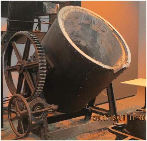
Figure 2. The main parameters of bevel gear pairs.
Based on it is visible that many parameters are needed for the exact description of the bevel gear. In case of this type, the teeth are situated parallel with the rotation axis of the cone body (Dudás Citation2011; Litvin and Fuentes Citation2004; Litvin Citation1972; Rohonyi Citation1980; Terplán Citation1975).
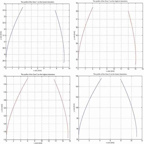
Figure 3. The profiles of bevel gear pairs on the main diameters (m = 10, z1 = 20, z2 = 30).
The aim of the TCA is the analysis of the developed mechanical parameters which have to be analysed on the gear connection. The main TCA parameters are the normal stress normal strain and normal deformation values which are determined perpendicularly to the gear surface (Argyris, Fuentes, and Litvin Citation2002; Fuentes and Iserte Citation2011; Kozák and Szeidl Citation0000; Litvin and Fuentes Citation2004; Páczelt, Szabó, and Baksa).
The production cost is very expensive because of the complex geometry, the tool costs, device cost, etc. That is why the real production has to be followed after the designing, the CAD modelling and the TCA analysis.
2. Designing of gear pairs
We have worked out a computer program because of the simplification of the geometric designing process. Previously the suggestions of the references have to be read (Dudley Citation1962; Litvin and Fuentes Citation2004; Litvin Citation1972; Rohonyi Citation1980; Terplán Citation1975). Knowing of the designing formulas the computer program could be written.
Input data for designing the drive pair are: m module, z1 number of teeth of the driver bevel gear wheel, z2 number of teeth of the driven gear wheel, c* root clearance factor and the α0 angle of contact (Dudley Citation1962; Litvin and Fuentes Citation2004; Litvin Citation1972; Rohonyi Citation1980; Terplán Citation1975). Knowing of them the program is calculated all necessary geometric parameters of the gear pairs and drawn the profile curves on the highest and the lowest diameters ().
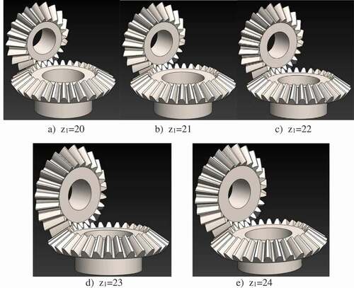
After the geometric calculation, the CAD models of the bevel gears could be created by SolidWorks software (). Interpolation B-spline has to be fit on the profile points. Knowing of the necessary profile curves the teeth could be created by extrusion.
Figure 4. The type of the CAD models of the designed gears.
On the calculated parameters of the bevel gears could be seen. After the geometric designing, the TCA could be followed.
Table 1. The calculated parameters of the designed bevel gear pairs
3. TCA analysis of connecting bevel gear pairs
3.1. The adoption of the finite element mesh
The appropriate selection of the finite element mesh is the basis of the calculation process (Kozák and Szeidl Citation0000; Páczelt, Szabó, and Baksa). One of the main property of the bevel gear the tooth thickness is continuously changing along the tooth length from the highest cone’s diameters to the lowest cone’s diameters. Because of this property the equable mesh subdivision could not be applied.
We have adopted a coordinate system in the middle of the teeth connection zone ().
Figure 5. The adoption of the coordinate system into the middle of the connection zone.
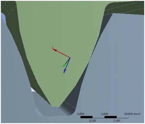
The x axis of the adopted coordinate system is shown in the normal direction of the connecting surfaces ().
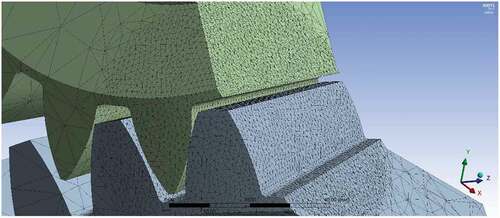
Sphere of influence meshing has been applied on the contact zone. The mesh shape is dense triangles. The density is 1.5 mm and the sphere radius is 38 mm. Automatic meshing has been applied on the outside of the contact zone ().
Figure 6. The adoption of the finite element mesh.
The type of the applied material has been structural steel ().
Table 2. The properties of the applied material
The driving bevel gear has been loaded by 600 Nm moment. Five degrees of freedom have been fixed on the driving gear only the turning motion around the axis of rotation has been let. The driven gear has been totally fixed.
3.2. Analysis of the normal stress
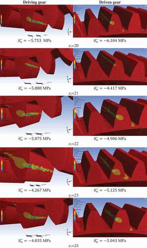
The normal stress is interpreted on perpendicular direction of the tooth surface (Kozák and Szeidl Citation0000; Litvin and Fuentes Citation2004; Páczelt, Szabó, and Baksa). This direction is the most determinative in the aspect of tooth deformation. This normal stress has been calculated for the tooth contact zone ().
Figure 7. Normal stress results for every bevel gear pairs.
Based on the calculations the normal stresses could be seen in the function of the number of teeth of the driving bevel gear on .
Figure 8. The developed normal stresses in the function of the number of teeth.
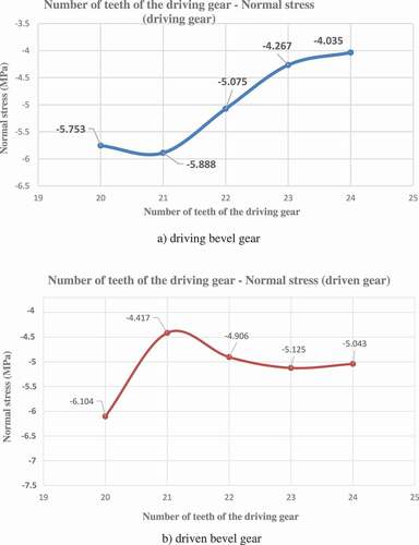
Based on the results the minimum normal stress of the surface of the driving bevel gear is developed in case of z1 = 24 number of teeth in absolute value. The minimum normal stress of the surface of the driven bevel gear is developed in case of z1 = 21 number of teeth in absolute value ().
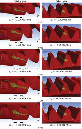
3.3. Analysis of the normal elastic strain
The normal elastic strain has been calculated for the tooth contact zone (). It is defined on the perpendicular direction for the tooth surface (Kozák and Szeidl Citation0000; Litvin and Fuentes Citation2004; Páczelt, Szabó, and Baksa).
Figure 9. Normal elastic strain results for every bevel gear pairs.
Based on the calculations the normal elastic strain could be seen in the function of the number of teeth of the driving bevel gear on .
Figure 10. The developed normal elastic strain in the function of the number of teeth.
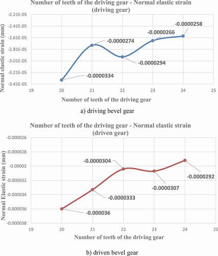
Based on the results the minimum normal elastic strain of the surface of the driving bevel gear is developed in case of z1 = 24 number of teeth in absolute value. The minimum normal elastic strain of the surface of the driven bevel gear is developed in case of z1 = 24 number of teeth in absolute value (). That is why the increasing of the number of teeth of the driving gear the normal elastic strain will be increased in case of both connecting tooth surfaces.
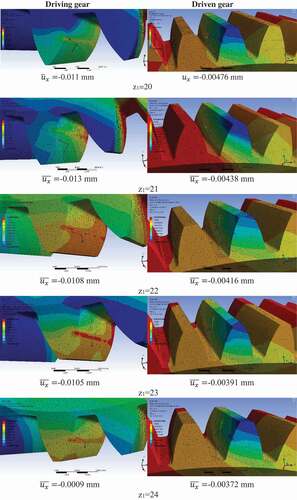
3.4. Analysis of the normal deformation
The normal deformation has been analysed into the x direction which is perpendicular for the contact surfaces (Kozák and Szeidl Citation0000; Litvin and Fuentes Citation2004; Páczelt, Szabó, and Baksa). This direction is the most determinative because the main deformation is applied into the perpendicular direction of the contact surfaces ().
Figure 11. Normal deformation results for every bevel gear pairs.
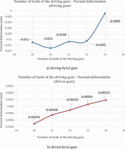
Based on the calculations the normal deformation could be seen in the function of the number of teeth of the driving bevel gear on .
Based on the results the minimum normal deformation of the surface of the driving bevel gear is developed in case of z1 = 24 number of teeth in absolute value. The minimum normal deformation of the surface of the driven bevel gear is developed in case of z1 = 24 number of teeth in absolute value (). That is why the increase of the number of teeth of the driving gear the normal deformation will be increased in case of both connecting tooth surfaces.
Figure 12. The developed normal elastic strain in the function of the number of teeth.
4. Conclusion
The aim of the research is the analysis of the modification of the number of teeth of the driving gear in the function of the TCA parameters (normal stress, normal, elastic strain and normal deformation).
Before the TCA the determination of the geometric parameters is needed. We have worked out a new-type computer-aided software which is helped us for the facilitation of the calculation process. This software is determined the necessary geometric parameters and the profile curves of the bevel gear pairs. After the process, the CAD models of the designed gears have to be created. Knowing of the profile curves an interpolation B-spline is fitted into the calculated points.
Based on the CAD models of the analysed gears the TCA analysis could be done. We have designed five types of bevel gear pairs. We have done the TCA analysis for every gear pairs.
The effect of the normal stress, normal elastic strain and the normal deformation has been analysed between the contact surfaces. After the analysis, we have evaluated the received results and created the functions separately for the driving gear and the driven gear. We could determine the consequences of these functions.
Acknowledgments
This research was supported by the János Bolyai Research Scholarship of the Hungarian Academy of Sciences.
Disclosure statement
No potential conflict of interest was reported by the author.
References
- Argyris, J., A. Fuentes, and F. L. Litvin. 2002. “Computerized Integrated Approach for Design and Stress Analysis of Spiral Bevel Gears.” Computer Methods in Applied Mechanics and Engineering 191: 1057–1095. Elsevier. doi:https://doi.org/10.1016/S0045-7825(01)00316-4.
- Dudás, I. 2011. Gépgyártástechnológia III., A. Megmunkáló Eljárások És Szerszámaik, B. Fogazott Alkatrészek Gyártása És Szerszámaik. Budapest: Műszaki Kiadó.
- Dudás, L. 1991. “Kapcsolódó Felületpárok Gyártásgeometriai Feladatainak Megoldása Az Elérés Modell Alapján.” Kandidátusi értekezés, Budapest, TMB. p.144, 2005.
- Dudley, D. W. 1962. „Gear Handbook”. New York-Toronto-London: MC Graw Hill Book Co.
- Erney, G. 1983. Fogaskerekek. Budapest: Műszaki Könyvkiadó. p. 460.
- Fuentes, A., and J. L. Iserte. 2011. “Gonzalez – Perez, I., Sanchez – Marin, F. T.: Computerized Design of Advanced Straight and Skew Bevel Gears Produced by Precision Forging.” Computer Methods in Applied Mechanics and Engineering 2363–2377. Elsevier. doi:https://doi.org/10.1016/j.cma.2011.04.006.
- Goldfarb, V., E. Trubachev, and N. Barmina. 2018. Advanced Gear Engineering. Springer. p. 197. ISBN 978-3-319-60398-8.
- Kozák, I., and G. Szeidl. 0000. Fejezetek a Szilárdságtanból, Kézirat, 2008 – 2012. Miskolci Egyetem. p.284. elektronikus jegyzet.
- Litvin, F. L. 1972. A Fogaskerékkapcsolás Elmélete. Budapest: Műszaki Könyvkiadó.
- Litvin, F. L., and A. Fuentes. 2004. Gear Geometry and Applied Theory. United Kingdom: Cambridge University Press. ISBN 978 0 521 81517 8.
- Páczelt, I., T. Szabó, and A. Baksa. A Végeselem Módszer Alapjai. Miskolci Egyetem. p.243.
- Rohonyi, V. 1980. Fogaskerékhajtások. Budapest: Műszaki Könyvkiadó.
- Terplán, Z. 1975. Gépelemek IV., Kézirat, 220. Budapest: Tankönyvkiadó.