Abstract
Liquid crystal photo‐alignment using azo‐dyes is reviewed. This alignment method is very different from previously reported ones, such as photo‐crosslinking, photo degradation and photo‐isomerization. It will be shown that this photo‐aligning method can provide a controllable pretilt angle and strong anchoring energy of the liquid crystal cell, as well as high thermal and UV stability. The application of this method to the alignment and fabrication of various types of liquid crystal displays is also discussed.
1. Introduction
The field of liquid crystal (LC) photo‐alignment is rapidly developing and a vast amount of new materials, techniques and LCD prototypes based on photo‐alignment (PA) technology have appeared recently Citation1–9. However, despite these potential advantages, the application of PA to LCD production is still limited to the laboratory. Large scale deployment of PA is hampered by the lack of a good material and by long term stability, not to mention the lack of suitable mass production scale equipment.
The effect of LC photoalignment is a direct consequence of the appearance of the photo‐induced optical anisotropy and dichroic absorption in thin amorphous films, formed by molecular units with anisotropic absorption properties Citation1. The first publication on LC photo‐alignment appeared in 1988, which discussed the application of a reversible cis‐trans isomerization of the azo‐benzene molecular layers Citation2. The optical control of LC alignment was made by changing the wavelength of the non‐polarized light illumination Citation2. Later it was shown that the alignment of a liquid crystal medium could be made by illuminating a dye doped polymer alignment layer with polarized light Citation3. LC molecules in contact with the illuminated area were homogeneously aligned perpendicular to the direction of the laser polarization and remained aligned in the absence of the laser light. Subsequently, LC photo‐alignment was also achieved using cinnamoyl side‐chain polymers Citation4 Citation5 and polyimide aligning agents Citation6. More recently, a new class of azo‐dyes have also been studied with excellent results Citation10 Citation11.
In this paper, we shall review the physical mechanism of this alignment process and report some new results related to the processing conditions using these azo‐dyes. In particular, we discuss the conditions where the light dosage is greatly reduced, to less than 50mJ/cm2. Applications of this new PA material to various types of LCD will also be reviewed.
2. Photo‐induced reorientation
Photo‐alignment can generally be classified into four categories according to their mechanism. They are (i) photochemically reversible cis‐trans isomerization in azo‐dye containing polymers, monolayers and pure dye films Citation12 Citation13; (ii) photochemical crosslinking in preferred directions of polymer precursors, such as cinnamoyl side‐chain polymers Citation4 Citation5; (iii) photodegradation and orientational bond breaking in polyimide materials Citation14 Citation15; and (iv) pure reorientation of the azo‐dye chromophore molecules or azo‐dye molecular solvates due to the diffusion under the action of polarized light Citation10 Citation11. Recently the method of repeated cis‐trans photoisomerization reaction resulting in the reorientation of the backbone structure of polyamic acid contained azobenzene units was reported Citation16 Citation17. The subsequent imidization stabilized the polyimide structure. The LC alignment was thermally and optically stable and no decomposition was involved.
Processes (i) and (iv) involving azo‐dyes present reversible transformations, while the other two processes require irreversible photo‐chemical changes. For these latter processes, since chemical changes occur, it is difficult to maintain the purity of the alignment layer. For cis‐trans isomerization the change of the absorption spectra is observed after illumination Citation12 Citation13, which is not the case for the photochemical stable azo‐dye molecules, involved in a reorientation and solvate formation process under the action of polarized light Citation10 Citation11. These two processes provide a high purity of the aligning layers suitable for the liquid crystal display applications with thin film transistors (TFT‐LCD). However there is a significant difference in their anchoring energies. The anchoring energy is also very strong (near 10−3 J/m2) for the UV light induced pure reorientation process. Our recent results also show that the photosensitivity can be reduced to 50mJ/cm2 for the alignment of the LC layer. Thus, of all the PA processes, we believe that (iv) with pure diffusion reorientation of the azo‐dye chromophore molecules or azo‐dye molecular solvates is the most promising one for large scale applications.
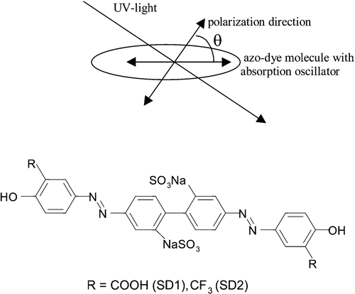
The mechanism of the photo‐orientation process is quite interesting. The UV light induces an asymmetric potential field under which the stable configuration is characterized by the dye absorption oscillator perpendicular to the induced light polarization. When the azo‐dye molecules are optically pumped by a polarized light beam, the probability for the absorption is proportional to cos2θ, where θ is the angle between the absorption oscillator of the azo‐dye molecules and the polarization direction of the light as shown in Figure Citation18. Therefore, the azo‐ dye molecules, which have their absorption oscillators (chromophores) parallel to the light polarization will most probably get an increase in internal energy, which results in more energetic rotational motion through internal energy transfer (electronic to rotation energy). Vibrational motions will probably occur but that does not affect the PA mechanism.
Figure 1 Photo‐induced order in photochemical stable azo‐dye films. The structure of azo‐dye molecule (sulfonic dyes, SD1, SD2) is also shown Citation10.
The increased rotational motion of the excited dye molecules is damped, resulting in a new orientation for the azo‐dye. This absorption‐rotation process will keep repeating itself until the chromophores have their absorption dipole oscillators perpendicular to the polarization of the input light. In that case there will be no absorption. The molecules will be at rest. Once all or most of the molecules are oriented this way, inter‐molecular interaction will lock their positions in place and prevent re‐diffusion and randomization even if the input light is turned off. This is a heuristic picture of the photo‐physical alignment process in these azo‐dyes.
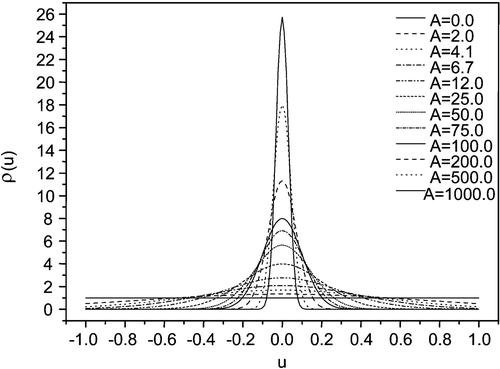
We have studied this UV light induced reorientation effect carefully. In our case the chromophore is parallel to the long molecular axis of the azo‐dye (Figure ), i.e. azo‐dye molecules are tending to align their long axes perpendicular to the UV‐light polarization. The statistical distribution of orientation of the molecules is described by the function f(θ) where θ is the angle between the molecular axis and the direction of the light polarization (Figure ). Obviously, the normalized f = 1/4π in the initial state, and the final desired state with total orientation is given by f = δ(θ−π/2). The situation is shown in Figure Citation18. At any light dosage, an intermediate distribution in thermodynamic equilibrium in the new oriented state will be established. Obviously this distribution can be related to the anisotropic dichroism or birefringence of the PA film. This dichroism can be measured and is related to the order parameter and related to f(θ). We shall make use of the induced order parameter as a measure of this effect of photo‐orientation in the azo‐dyes.
Figure 2 The distribution functionρ(u) = 4πf(u), u = cosθ of the azo dye molecules for various values of the parameter A (2), proportional to the intensity of the activated light Citation18.
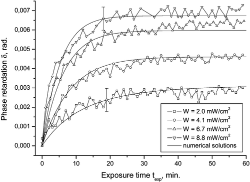
This model has been verified by several experiments. Figure shows the measured retardation of the PA film as a function of exposure time together with the theoretical fits. Since the retardation of the film is directly proportional to the order parameter P 2, this result confirms the diffusion model, and gives the diffusion coefficient at the same time.
Figure 3 The photo‐induced birefringence δ of the azo dye SD‐1, as a function of the exposure time for different exposure powers. The experimental data is an agreement with the calculations according to the model of Brownian rotatory diffusion of azo‐dye molecules under the action of polarized light (solid lines) Citation18.
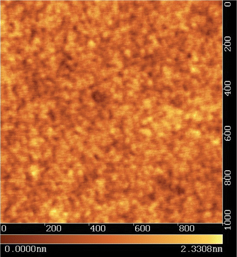
One immediate question about the diffusion model is that if the alignment of the azo‐dye molecules is induced by the linearly polarized light, will the alignment be randomized by thermal motion after the light is turned off? The answer is actually quite intriguing. It turns out that the inter‐molecular interaction in the reoriented azo‐dye molecular domain cannot be easily destroyed by a thermal motion Citation18. The behavior of the order parameter is given in Figure . The UV light is turned off at different times. It can be seen that the retardation of the alignment film or the order parameter first drops slightly, and then remains constant. The final value of the order parameter depends on the exposure time. The solid lines in Figure are theoretical fits to the data points, which were experimentally measured. It can be seen that the diffusion model works very well. Actually the photo‐aligned azo‐dye molecules produce a very smooth and uniform structure with the thickness of several nanometers controlled by the concentration of the azo‐dye in an organic solvent e.g. N,N‐dimethylformamide (DMF) Citation11. The change of the azo‐dye concentration between 0.4 and 1.3 wt/wt % concentration results in the thickness variation of the photo‐alignment layer between 3 and 12 nm Citation19. AFM picture of a sulphuric azo‐dye (SD‐1) film with a thickness of 20 nm on top of ITO film is shown in Figure .
Figure 4 The relaxation of azo‐dye layer birefringence, proportional to order parameter after switching off the activated light for different exposure times toff shown in the figure. The modified potential in diffusion model includes the effect of molecular interaction Citation18.
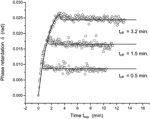
Experimentally, we can only measure the photo‐induced birefringence δ of the dye film. We argue that δ is proportional to the order parameter S via δ = kS, where k is a fixed constant Citation9. The value of δ versus exposure time texp, is measured with high accuracy with the help of the PEM (photo‐elastic modulator). The rate of the order parameter increase with the exposure time becomes higher for the higher values of the illumination power, which is in agreement with a model of Brownian rotatory diffusion of azo‐dye molecules under the action of polarized light. The diffusion model of the light induced reorientation of azo‐dye molecules is in a good agreement with experimental data as shown in Figures and .
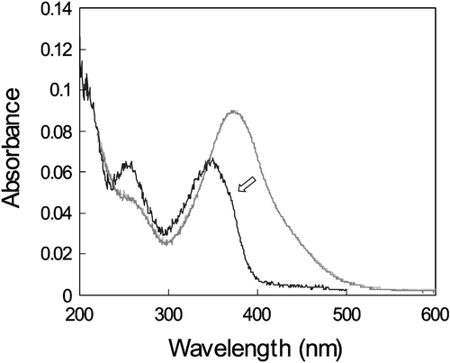
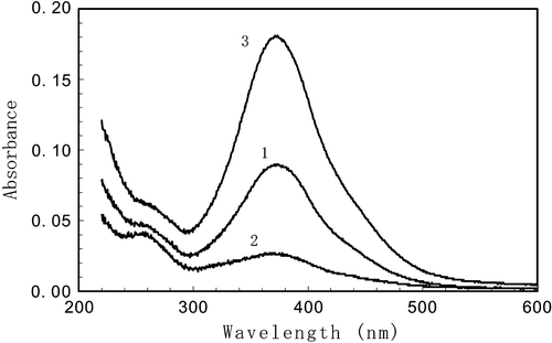
Figure shows the polarized absorption spectra (absorbance or optical density) before (curve 1) and after (curves 2 and 3) the UV irradiation. Before the irradiation the absorption of the azo dye layer does not depend on the polarization of the light, used in measurements. After irradiation by a linearly polarized UV light, the absorption of light with the polarization direction parallel to the polarization direction of the activated light (D∥) decreases (curve 2, Figure ) while that one with orthogonal polarization direction (D⊥) increases (curve 3, Figure ). The evolution of the polarized absorption spectra after UV‐illumination does not reveal any noticeable contribution of photochemical reactions Citation10, as the average absorption
Figure 6 Absorption spectra of SD‐1 layer before the polarized UV exposure (curve 1). Curves 2 and 3 show the polarized absorption spectra after the exposure by a polarized UV light in the direction parallel (D∥) and perpendicular (D⊥) to the activating light polarization accordingly Citation10.
3. Photo‐polymerized azo‐dyes. UV and thermal stability.
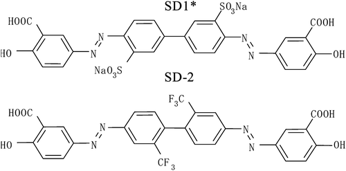
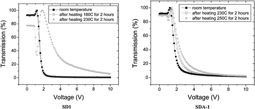
There are two more azo‐dyes SD1* and SD‐2 were also synthesized (Figure ). The order parameter of these azo‐dyes was less, than that of SD‐1, while the absorption spectra were almost the same Citation11 (Figure ). Besides that SD1* was capable to orient LC molecules perpendicular rather than parallel to the LC director. In order to improve the durability against light exposure and moisture, the polymerization of the azo dyes after the photoalignment was investigated, synthesizing azo dye monomer SDA1 shown in Figure Citation11. It was dissolved in DMF and doped by 0.02% of a thermal polymerization initiator V‐65 (form Wako Pure Chemicals Industries, Ltd.). The mixture was spin‐coated onto glass substrates and photoaligned in the same manner as SD1. After the photoalignment, the SDA1 film was heated at 150°C during 1 hour for the purpose of thermal polymerization. LC on the SDA1 film was aligned in the same direction as SD1. LC alignment properties of the polymerized azo‐dye layer were thermostable up to 250°C, while SD‐1 has degraded at this temperature (Figure ). Improvement of durability against UV light exposure in the LC cell using SDA1 photo‐aligned film after the thermal polymerization was also confirmed. The dose of UV‐light of 175 MJ/m2 can be tolerated by SDA‐1 layer, while SD‐1 layer is destroyed by this UV light dosage. Moreover, the absorption band of SDA‐1 is shifted to the UV region, thus making the azo‐dye aligning layer more stable to the exposure in the visible region (Figure ). Later the COOH substituent in the formula of SDA‐1 (Figure ) was replaced to CF3, thus making the compound more stable against the hydrolysis decomposition. The new photo‐polymerized azo‐dye was called SDA‐2.
Figure 8 Azo dye monomer SDA1Citation11.

4. LC surface interaction in a photo‐aligned cell
Usually the azimuthal anchoring energy of photo‐aligning materials is rather small (about 1–7×10⁻⁶ J/m2), which is about an order of magnitude smaller than the value obtained by the rubbing method Citation20–24. A perfect quality homogeneous alignment was obtained on polyimide films, but a relatively high energy of illumination (≈7 J/cm2) was needed to get the required maximum order parameter Citation7. If the illumination energy (λ = 257 nm) exceeds 7 J/cm2, the alignment became loose and soon mono‐domain LC alignment was not induced in accordance with the origin of the photochemical mechanism of photo‐alignment.
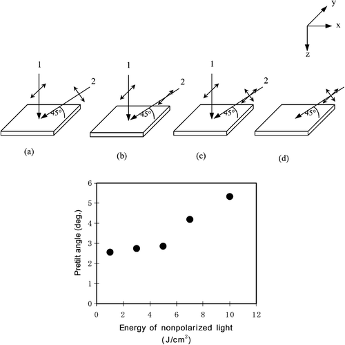
We studied the LC aligning properties of the azo‐dyes. As mentioned above, the alignment mechanism is that of photo‐induced orientational ordering. The light‐induced alignment should lock in place due to inter‐molecular interaction even when the light is switched off as shown in Figure . In practice, however, it is more stable to use polymerized azo‐dyes shown above to “fix” the dye molecules. We have measured various properties of the alignment film and the corresponding LC cells Citation10 Citation11 Citation23. First, the temperature stability was checked. The temperature stable pretilt angle of 5.3° was obtained by a two‐step exposure of azo‐dye film using normally incident polarized light followed by oblique non‐polarized light (Figure ). The pretilt angle was temperature stable and does not change after heating the sample up to 100°C for two hours.
Figure 11 Above: Various methods of UV light irradiation to attain the pretilt angle of LC layer on the photo‐aligned film . The activated UV light propagates in xz plane at an oblique angle with the substrate θ = 45°. Below: Dependence of the pretilt angle on the energy density of the obliquely irradiated nonpolarized light after the irradiation of vertical polarized light (case c, above) with the energy density of 10 J/cm2 Citation10.
The azimuthal anchoring energy Wϕ of a photo‐aligned substrate was measured Citation23. It was found that the anchoring energy was very high and >10−4 J/m2, which is the same as the anchoring of the rubbed polyimide (PI) layer. As a comparison, in photo‐polymerized azo‐dye layers, the azimuthal and polar anchoring energies were about 1.5⋅10−5 J/m2 and 3⋅10−4 J/m2 for the exposure dose less than 1 J/cm2. Thus the reorientation effect can provide very strong anchoring. This is probably due to the large order parameter that can be achieved with this process. Most of the dye molecules participate in this alignment process, versus perhaps a small fraction in photo‐polymerization.
We have also studied the effect of the thickness of the azo‐dye layer on the LC alignment quality. The azo‐dye can be used to align the LC even at very small thickness. We measured the anchoring energy of the PA layer as a function of the layer thickness. Figure shows the results. It was found that even a 1nm thick (almost a monolayer) layer could produce alignment. However the anchoring energy was reduced by a factor of two.
Figure 12 LC polar and azimuthal anchoring energy as a function of the thickness of SD‐1 photoaligning layer.
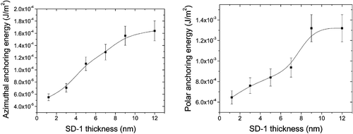
The results can be understood by noting that the film with a thickness of 1nm may not be continuous. In fact it should be in the form of islands. Thus the coverage of the substrate is not perfect leading to weaker alignment effects. However, alignment of LC does not require a continuous film due to the tendency of the LC molecules to align themselves to minimize elastic deformation energy. The result is that there is still alignment of the LC by the discontinuous layer but the anchoring energy is reduced. Figure points to the fact that the alignment is a surface effect. Once a continuous film is obtained, LC alignment can be achieved with good anchoring properties. This is another supporting fact that the azo‐dyes are good agents for PA.
We have also demonstrated that a super‐thin photo‐aligned layer azo‐dye layer can be used for LC photo‐aligning. This new method includes the formation of a very neat “textile knitwear” by a super‐thin SD‐1 layer and allows us to avoid the spin‐coating procedure. Moreover, the photosensitivity of azo‐dye after photo‐alignment can be further reduced and “island” azo‐dye structure onto the rough ITO surface can be prevented due to better adhesion of SD‐1 molecules. Using this super‐thin SD‐1 layer as an alignment agent, the sufficiently high polar and azimuthal anchoring energy and a perfect LC alignment can be obtained Citation25. The method allows for a perfect LC photo‐alignment in large or curved cells and is very attractive for mass production.
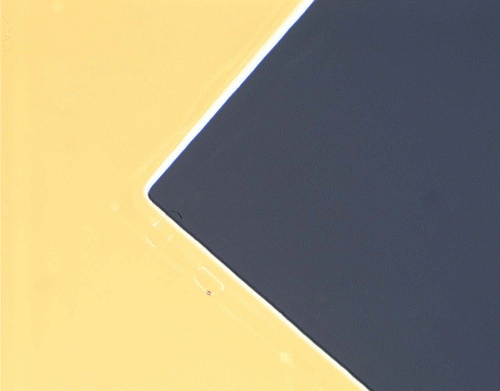
The value of voltage holding ratio (VHR) was also measured. The measured values for the photo‐aligned LC cell (>99% at 80°C) and residual DC voltage (<50mV) were found to be even better than those for rubbed PI layers. This implies that the azo‐dyes studied can be applied as aligning layers in thin film transistor liquid crystal displays (TFT‐LCDs), as their purity is high enough and there is no additional ionic impurity from the aligning layers both in the volume and the surface of LC cell. The quality of a photo‐aligned TN cell is shown in Figure Citation11.
Figure 13 Polarized microscope photograph of LC alignment on photoaligned polymerized azo‐dye film Citation11. The size of the picture is 1mm2. Both homogeneous and twist LC alignment looks perfect between crossed polarizers as black and yellow regions.
5. Sensitivity of the azo‐dye aligning layers
One consequence of the diffusion nature of our PA material is that temperature and other environmental effects become quite important. We found that the sensitivity or the light dosage required for producing alignment can change by an order of magnitude by varying the environmental conditions during the PA process. Physically, the result can be easily understood. The presence of foreign molecules inside the azo‐dye film can affect greatly the ease of rotational diffusion during the PA process. In particular, moisture inside the solid film is detrimental to rotational reorientation due to the polar nature of water molecules. In the standard PA procedure, the alignment layer is first soft baked to drive out most, but not all of the solvents. SD1 is highly hygroscopic. It can thus absorb moisture, which will affect the PA process by providing much resistance to the rotational motion. Recently we synthesized azo‐dye derivatives, which are water non‐soluble and thus more resistant to the effect of moisture.
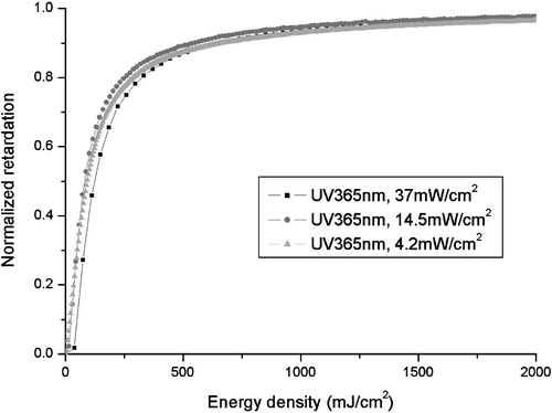
We also examined the effect of light intensity on the PA process. The idea is to see if there is any nonlinear effect so that a higher power light source will require less light dosage. Figure shows the results Citation26. It can be seen that the order parameter obtained is dependent only on the light dosage in J/cm2. In other words, it does not matter if the light intensity is high and the exposure time is short, or if the light intensity is low and the exposure time is long. Thus in actual applications, it is desirable to save processing time by having high intensity light sources. From Figure , it can be seen that the order parameter is significant even at very low light dosages of less than 50 mJ/cm2. Experimentally, we found that indeed even with a light dosage of 50 mJ/cm, perfect alignment can be achieved in the LC cell. Recently we have synthesized certain azo‐dye derivatives, which considerably improve the sensitivity of SD‐1, so very low dosage of UV‐light is sufficient for a perfect uniform alignment of LC cell: 150 mJ/cm2 for a non‐polarized light and 20 mJ/cm2 for a polarized light.
6. Applications
6.1 Photo‐aligning of ferroelectric LC
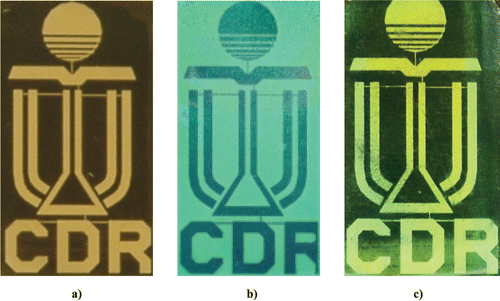
A remarkable property of azo‐dye aligning layers gives a good chance to provide a high photoalignment quality of FLC using the azo‐dye layer. The photo‐aligned FLC cell appeared to be better than prepared by buffing, if the UV‐irradiation time of the azo‐dye layer is high enough Citation27. The FLC row addressing response time of τ≈100 µs at the voltage pulse amplitude of U = ±15V was demonstrated Citation27 Citation28. Large FLC cell gaps of 5 µm and 7 µm were used, which is easy in manufacturing. Perfect electrooptical performance of the photo‐aligned FLC display with a memorized gray scale was demonstrated (Figure ). A prototype of passively addressed passive matrix FLC display based on the photo‐alignment technique was developed Citation28. Recently photoaligned bistable FLCs with dichromatic (two color) Citation29 and almost achromatic (black/white) viewing Citation30 were realized (Figure ).
Figure 15 Photo‐aligned passive matrix FLC display with a memorized gray scale Citation27 Citation28.
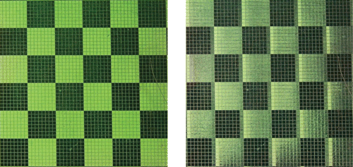
Figure 16 Photoaligned bistable FLC display with dichromatic, two color, a), b) Citation29 and almost achromatic, black/white, c) Citation30 switching.
6.2 Photo‐aligning of vertical aligned nematic (VAN) mode
VAN‐LCD has become very popular for LCD TV applications because of the high contrast and wide viewing angle it affords. Vertical photo‐alignment has been attempted. A high pretilt angle from homeotropic LC configuration was obtained by in‐situ photoalignment method Citation31. However notwithstanding the efforts the VAN‐LCDs prepared by photoaligning technique have not yet reached the appropriate quality (response time, contrast ratio) in comparison with conventional LCDs, prepared by rubbing technology Citation9.
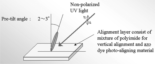
The application of modern commercial VAN aligning agents with high resistivity to UV light in combination with photoaligned azo‐dye materials Citation10 Citation11 can help to overcome the above‐mentioned drawbacks. In experiment Citation32 the commercially available polyimide (PI) for homeotropic alignment was used in a combination with azo‐dye for varying the pretilt angle from the homeotropic direction. The composition of 1% of azo‐dye in solution with PI was prepared and the photo‐aligning films were illuminated by a slantwise nonpolarized light. For comparison the aligning film of a pure PI was prepared by rubbing technique to align the LC molecules in a homeotropic state with some pretilt angle. The measured value of the pretilt angle from the homeotropic alignment was about 1.4°, which is higher than in other photo‐aligned VAN LC cells (0.53°). Later the pretilt angles of 2–3° from the homeotropic LC orientation were obtained using the mixture of homeotropic PI and photopolymerized azo‐dye SDA‐2 (Figure ) Citation11.
Figure 17 Preparation of pre‐tilted vertical alignment for VAN‐LCD by a photo‐alignment method Citation30 .
While the pretilt angle is adequate, the response time needs to be studied as well. The response times of photoaligned and conventional rubbing VAN LCD were measured. The results indicate almost no change, with τon+τoff = 7.8ms+9 ms for the former and τon+&off = 8.1 ms+8.9 ms for the latter. Probably this means that azo‐dye as a dopant in PI has increased further the azimuthal anchoring strength in the photo‐aligned VAN‐LCD cells. The high values of VHR for the photo‐aligned VAN‐LCD using azo‐dye/PI composition of 94–96% (close to the conventional rubbed VAN‐LCD with VHR = 98%) testify to this point. The measured value of the contrast ratio between “off” and “on” states in all the cases exceeds 1000:1 in the monochromatic light (λ = 632.8nm). Thus it is concluded that azo‐dyes are suitable for the alignment of VA‐LCD.
6.3 Photo‐aligned bistable π‐BTN display
The high pretilt angle, made by photo‐aligning was demonstrated recently to enable bistable switching with inherent long term optical memory in 2π‐BTN (bistable twisted nematic) cell Citation33. Meanwhile, the bistability of π‐BTN is based on asymmetric anchoring of the LC cell Citation34 Citation35. We fabricated truly bistable π‐BTN display, based on photoaligning technology Citation36. The strong anchoring surface was achieved by the usual rubbed polyimide (PI) layer. Such PI layer provides a strong polar anchoring energy of 1.5×10⁻³ J/m2. We found that the polar anchoring energy of photo‐polymerized azo‐dye SDA‐1 (SDA‐2) can be adjusted to 1.5–2.8⋅10−4 J/m2, while azimuthal anchoring to 3.6–5.6⋅10−5 J/m2 by changing the exposure time, which was suitable for obtaining π‐BTN bistability by surface anchoring breaking. The π‐BTN LCD was switched between −22.5° and 157.5°, exhibiting a high contrast ratio (CR>140) and wide viewing angles (Figure ) Citation36. π‐BTN was also successfully made on flexible plastic substrates by using photo‐alignment technology Citation37. This facilitates the implementation of low‐power consumption bistable liquid crystal display into smart cards (Figure ) Citation38.
Figure 18 Photo‐aligned π ‐BTN liquid crystal display Citation36.
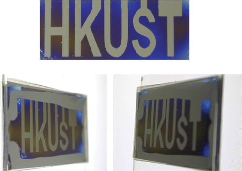
Figure 19 Reflective flexible photoaligned TN‐LCD mounted in smart card prototype Citation38.

6.4 Photo‐aligned nematic displays on plastic substrates
We have also investigated the properties of azo‐dye alignment on plastic substrates Citation37 Citation38. Excellent alignment with a high anchoring energy was achieved with the exposure energy less than 1.0 J/cm2, which corresponds to the azimuthal anchoring energy >10−4 J/m2. We used a mixture of azo‐dye SD‐1 (Figure ) with a mentioned above thermo‐polymerized azo‐dye SDA‐2 for the display fabrication. The LC pretilt angle of about 5° on the plastic substrate was made by a double exposure method (Figure ). To demonstrate the alignment quality on plastic substrates a 9‐digit reflective passive matrix TN‐LCD mounted in a smart card was fabricated (Figure ). To maintain a uniform cell gap of 8 µm (second Mauguin minimum of MLC‐6809‐000 Merck LC mixture), semi‐dry adhesive spacers were chosen. The electrooptical performance of the photo‐aligned plastic display was very similar to common TN‐LCD fabricated for comparison by usual rubbing method on glass substrate.
6.5 Optically rewriteable LC display with a high contrast and long life time
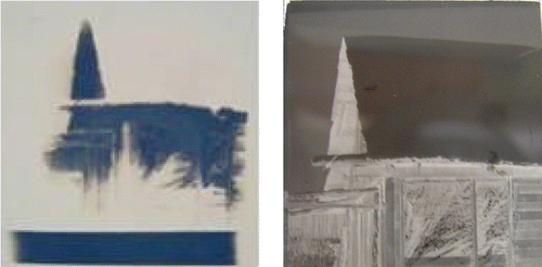
We propose an optically rewriteable twisted nematic liquid crystal display (TN‐LCD), based on photoaligning technology Citation39. TN‐LCD does not require an electronic scheme, a power supplier or conductive layers inside devices, which provides a possibility to use this type display in plastic cards, registration and other systems. An optically rewriteable LC display shows a high contrast and a long life‐time. We propose to use TN‐LCD cell with special alignment layers and without conductive layers. In our display we change LC orientation on the alignment layer by a polarized light. The similar devices in twist LCD cell with light controllable azimuthal anchoring energy were first reported by Yamaguchi et al. Citation40 Citation41. Our photosensitive azo‐dye material SD‐1 (Figure ) reversibly changes the orientation in the plane of the substrate, while the other substrate keeps a strong azimuthal anchoring energy. It gives a possibility to change the twist angle in LC cell. For a dark state we use the structure with a zero twist angle and for a bright state –the structure with the twist angle close to 90° between two crossed polarizers, and apply a special mask to create the image (Figure ). Any gray level can be realized in such an image, as azimuthal anchoring energy and consequently the apparent twist angle are proportional to the intensity of UV light passed through the mask Citation39. As azo‐dye SD‐1 can change its alignment reversibly without any photochemical transformations and photo‐chemical reactions, our procedure will allow us to erase and write images an unlimited number of times. As the sensitivity of new SD‐1 modifications for polarized light is about 20 mJ/cm2 Citation26 for a polarized light the usual UV lamp with a polarizer can erase and write the image in several seconds. The image can be kept for an infinitely long time, provided that UV polarized light of 365 nm is avoided and can be readable only, if a polarizer is used. The latter is quite reasonable for such application, as plastic displays for credit cards.
6.6 Photo‐patterned superthin polarizers and phase retarders
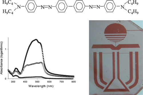
Polarizers and phase retarders remain very important components, which define the quality of LCD TV, desk top and notebook LCD monitors. There is a strong requirement to improve the quality of these components, using certain new materials, such as lyotropic LCs Citation42 or TAC (tri‐acetyl cellulose) films Citation43. LCDs with internal polarizers and phase retarders demonstrate many advantages in comparison with common LCD configurations, such as the elimination of a parallax effect and parasitic reflections, high brightness, contrast ratio and wide viewing angles Citation42. The new LCD configurations with patterned phase retarders and polarizers can be used for highly efficient transflective LCDs, working both in transmissive and reflective modes Citation44 and 3D displays Citation45. The existing polarizers for LCDs suffer from expensive and complicated implementation: they require protection films, adhesive layers, anti‐reflection coating etc. They are very thick (150–400 µm) and possess such disadvantages as light losses through additional reflections and parallax effect, poor brightness, low contrast and limited viewing angles. We have developed new photo‐alignment methods to fabricate thin internal patterned (pixelated) polarizers with different local orientations of the absorption axis and/or absorption colors Citation46 Citation47. To prepare these novel polarizers we used lyotropic LCs and novel photo‐alignment materials based on photo‐chemically stable azo‐dye films. These materials exhibit a high photoinduced order after absorption of a linearly polarized or non‐polarized light. Our new methods allowed the production of a defect‐free highly uniform alignment of lyotropic LC with a fine resolution of the polarization pattern (10 microns or less). The photo‐aligned internal polarizers are cost‐effective and enable new LCDs with excellent electrooptical response, including good viewing angles and high brightness. Figure shows the chemical formula of one of these azo‐dye material AD‐1, and photo‐patterned polarizer, made by photoaligning and photo‐patterning of lyotropic LC materials. The dichroic ratio of AD‐1 material is D⊥/D∥ = 20.4 within the blue region λ = 490 nm with the transmission of about 40%, which corresponds to a polarization efficiency of more than 98% (orange polarizer). The photo‐patterned color (orange) polarizer can be also prepared directly in a sufficiently thick (one micron) layer of azo‐dye AD‐1 by the photo‐aligning technique Citation9. The photoinduced anisotropy in this layer has not changed for years and is stable up to 130°C. The spectra can be made close to neutral by a special treatment with iodine or other vapors.
Figure 21 Azo‐dye AD‐1 chemical formula, absorption spectra (compare with Figure for SD‐1) and photo‐patterned polarizer, prepared by photo‐aligning of lyotropic LC Citation46 Citation47.
The patterned phase retarders for the LCD birefringent color generations were first proposed by us long ago Citation48. Later, we proposed a novel method to prepare an internal phase retarder using UV‐cured photo‐polymerized material Citation49. The photo‐induced birefringence value Δn of 0.125–0.153 was obtained depending on the polymerization temperature. This opens up a new dimension for gray‐scale compensation, where proper matching in the electro‐optic characteristics is crucial. The preparation of photo‐aligned internal phase retarders based on lyotropic LCs, transparent in the visible region is also under way.
6.7 Photo‐alignment technology for liquid‐crystal‐on silicon microdisplays
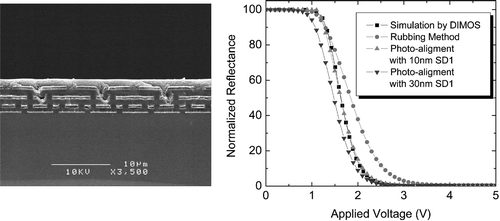
We have developed a photo‐alignment technology for liquid‐crystal‐on silicon (LCOS) microdisplays Citation50. A three step exposure process was proposed to improve the quality of LC tilted alignment on the photoaligned surface. Both azimuthal and polar anchoring energies on the photoaligned surfaces were high and comparable to those of rubbed polyimide layers. Consequently, photoaligned LCOS panes have the same electrooptical characteristics as usual ones prepared by rubbing (Figure ). A high contrast and fast response were demonstrated, which meet microdisplay standards. It was also observed, that defects were greatly reduced in photo‐aligned LCOS microdisplays due to the non‐contact nature of photoaligning technology Citation50.
Figure 22 Photoaligned LCOS microdisplayCitation50. Left: SEM image of a cross section of a color silicon panel. Right: comparison of the normalized reflectance between LCOS microdisplays made by rubbing and photoalignment; the results of the simulation using DIMOS program are also shown.
8. Conclusions
In this paper we have briefly reviewed a new photo‐aligning technology based on photo‐induced reorientation of dye molecules. We have shown that basic optical studies are consistent with the notion that the dye molecules reorient themselves in the potential field generated by the light and are held in place by their intermolecular potentials. We have also pointed out that the processing condition can be quite important, with a minimum sensitivity of 20 mJ/cm2 possible under the best conditions. This is highly desirable for manufacturing.
As well, we considered the temperature and UV‐stability of such LC photo‐alignment with a sufficiently high pretilt angle. The possibility to use this new photo‐aligning layer for FLCD, VAN‐LCD, π‐BTN LCD, optical rewritable memory, superthin polarizers and phase retarders, microdisplays, and TN‐LCD on plastic substrates has been also demonstrated.
Acknowledgements
We wish to thank the Hong Kong Research Grant Council for financial support under grant HKUST6149/04E and ITS/111/03.
References
- Kvasnikov , E. D. , Kozenkov , V. M. , Barachevskii , V. A. and Akademii , Dokladi . 1977 . Nauk SSSR , 237 : 633
- Ichimura , K. , Suzuki , Y. , Seki , T. , Hosoki , A. and Aoki , K. 1988 . Langmuir , 4 : 1214
- Gibbons , W. M. , Shannon , P. J. , Sun , S. T. and Swetlin , B. J. 1991 . Nature , 351 : 49
- Schadt , M. , Schmitt , K. , Kozenkov , V. and Chigrinov , V. 1992 . Jpn. J. Appl. Phys , 31 : 2155
- Dyadyusha , A. G. , Marusii , T. Ya. , Reznikov , Yu. A. , Khizhnyak , A. I. and Reshetnyak , V. Yu. 1992 . JETP Lett , 56 : 17
- Hasegawa , M. and Taira , Y. 1995 . IDRC'95 Digest , : 213
- O'Neill , M. and Kelly , S. M. 2000 . J.Phys. D , 33 : R67
- Schadt , M. 2001 . Mol. Cryst. Liq. Cryst , 364 : 151
- Chigrinov , V. G. , Kozenkov , V. M. and Kwok , H. S. 2003 . Optical Applications of Liquid Crystals , Edited by: Vicari , L . 201 – 244 . Philadelphia : Institute of Physics Publishing . edited by
- Chigrinov , V. , Prudnikova , E. , Kozenkov , V. , Kwok , H. , Akiyama , H. , Kawara , H. , Takada , H. and Takatsu , H. 2002 . Liq. Cryst , 29 : 1321
- Takada , H. , Akiyama , H. , Takatsu , H. , Chigrinov , V. , Prudnikova , E. , Kozenkov , V. and Kwok , H. 2003 . SID'03 Digest , : 620
- Pedersen , T. G. , Ramanujam , P. S. , Johansen , P. M. and Hvilsted , S. 1998 . J. Opt. Soc. Amer , 15 : 2721
- Statman , D. and Janossy , I. 2003 . J. Phys. Chem , 118 : 3222
- Nishikawa , M. , Taheri , B. and West , J. L. 1998 . Appl. Phys. Lett , 72 : 2403
- Gong , S. , Kanicki , J. , Ma , L. and Zhong , J. 1999 . Jpn. J. Appl. Phys , 38 : 5996
- Park , B. , Jung , Y. , Choi , H.‐H. , Hwang , H.‐K. , Kim , Y. , Lee , S. , Jang , S.‐H. , Kakimoto , M. and Takezoe , H. 1998 . Jpn. J. Appl. Phys , 37 : 5663
- Sakamoto , K. , Usami , K. , Kikegawa , M. and Ushioda , S. 2003 . J. Appl. Phys , 93 : 1039
- Chigrinov , V. , Pikin , S. , Verevochnikov , A. , Kozenkov , V. , Khazimullin , M. , Ho , J. , Huang , D. and Kwok , H. S. 2004 . Phys. Rev. E , 69 : 061713
- Pozhidaev , E. , Chigrinov , V. , Huang , D. , Zhukov , A. , Ho , J. and Kwok , H. S. 2004 . Jpn. J. Appl. Phys , 43 : 5440
- Hahn , S.‐K. and Kang , D. 2003 . IMID'03 Digest , : 619
- Thieghi , L. T. , Barberi , R. , Bonvent , J. J. , Oliviera , E. A. , Giacometti , J. A. and Balogh , D. T. 2003 . Phys. Rev. E , 67 : 041701
- Lu , X. , Lu , Q. and Zhu , Z. 2003 . Liq. Cryst , 30 : 985
- Chigrinov , V. , Muravski , A. , Kwok , H. S. , Takada , H. , Akiyama , H. and Takatsu , H. 2003 . Phys. Rev. E , 68 : 061702
- Kozenkov , V. M. , Chigrinov , V. G. and Kwok , H. S. 2004 . Mol. Cryst. Liq. Cryst , 409 : 251
- Li , X. , Kozenkov , V. , Yeung , F. , Xu , P. , Chigrinov , V. G. and Kwok , H. S. 2006 . Jpn. J. Appl. Phys. , 45 : 203
- Kwok , H. S. , Chigrinov , V. G. , Takada , H. and Takatsu , H. 2005 . IEEE/OSA J. of Disp. Techn , 1 : 41
- Huang , D. D. , Pozhidaev , E. P. , Chigrinov , V. G. , Cheung , H. L. , Ho , Y. L. and Kwok , H. S. 2004 . Displays , 25 : 21
- Huang , D. D. , Pozhidaev , E. P. , Chigrinov , V. G. , Cheung , H. L. , Ho , Y. L. and Kwok , H. S. 2004 . J. of SID , 12 : 455
- Valyukh , I. , Valyukh , S. , Skarp , K. and Chigrinov , V. 2005 . EuroDisplay 2005 Digest , : 305
- Xu , P. , Li , X. and Chigrinov , V. 2006 . Jpn. J. Appl. Phys. , 45 : 200
- Jeon , Y.‐J. , Hwang , J.‐Y. , Seo , D.‐S. , Nam , S.‐H. and Han , J.‐I. 2004 . Mol. Cryst. Liq. Cryst , 412 : 269
- Konovalov , V. A. , Chigrinov , V. G. , Kwok , H. S. , Takada , H. and Takatsu , H. 2004 . Jpn. J. Appl. Phys , 43 : 261
- Stalder , M. and Schadt , M. 2003 . 30 : 285
- Martinot‐Lagarde , P. and Dozov , I. 2003 . Proc. of SPIE , : 25
- Dozov , I. , Nobili , M. and Durand , G. 1997 . Appl. Phys. Lett , 70 : 1179
- Yeung , F. and Kwok , H. S. 2003 . Appl. Phys. Lett , 83 : 4291
- Li , X. , Yeung , F. , Chigrinov , V. G. and Kwok , H. S. IDW'05 Digest , pp. 883
- Osterman , J. , Tong , A. , Skarp , K. , Chigrinov , V. and Kwok , H. S. 2005 . J. of SID , 13 : 1
- Murauski , A. , Chigrinov , V. , Li , X. and Kwok , H. S. IDW'05 Digest , pp. 131
- Yamaguchi , R. , Goto , Y. and Sato , S. 2002 . Jpn. J. Appl. Phys , 41 : L889
- Yamaguchi , R. , Kawamura , T. and Sato , S. 2004 . IDW'04 Digest , : 39
- Ukai , Y. , Ohyama , T. , Fennell , L. , Kato , Y. , Paukshto , M. , Smith , P. , Yamashita , O. and Nakanishi , S. 2004 . SID'04 Digest , : 1170
- Mori , H. 2005 . IMID'05 Digest , : 1071
- Lim , Y.‐W. , Kim , J. and Lee , S.‐D. 2005 . IMID'05 Digest , : 1880
- Ham , H. , Lee , J. , Jang , H. , Song , M. and Kim , B. 2005 . SID'05 Digest , : 94
- Kozenkov , V. M. , Yip , W. C. , Tang , S. T. , Chigrinov , V. G. and Kwok , H. S. 2000 . SID'00 Digest , : 1099
- Yip , W. C. , Kwok , H. S. , Kozenkov , V. M. and G.Chigrinov , V. 2001 . Displays , 22 : 27
- Yakovlev , D. A. , Simonenlo , G. V. , Kozenkov , V. M. , Chigrinov , V. G. and Schadt , M. 1993 . Digest of Eurodisplay '93 , : 17
- Chigrinov , V. G. , Kwok , H. S. , Yip , W. C. , Kozenkov , V. M. , Prudnikova , E. K. , Tang , B. Z. and Salhi , F. 2001 . SPIE Digest , 4463 : 117
- Zhang , B. , Li , K. , Chigrinov , V. , Kwok , H. S. and Huang , H. C. 2005 . Jpn. J. Appl. Phys , 44 : 3983
