
 ?Mathematical formulae have been encoded as MathML and are displayed in this HTML version using MathJax in order to improve their display. Uncheck the box to turn MathJax off. This feature requires Javascript. Click on a formula to zoom.
Abstract
To meet the needs for higher-ranked roads and traffic loads, rigid slab pavements with cement-bound bedding material and joints were analysed instead of the traditionally used unbound construction method. Since the bearing capacity and drainage of the upper base course are essential, the results of recently introduced laboratory fatigue tests for permeable concrete were considered. Additionally, fatigue tests were also conducted on concrete and natural stone slabs. The structural response of the superstructure was determined by introducing an finite-element-model that considers bound behaviour in the joints and between the slab-bedding-interface. With the derived fatigue criterions and the structural primary response of the FE Model, the deterioration under traffic load can be evaluated. The main objective of this paper is the development of a design procedure for slab pavements with cement-bound joints and bedding on a pervious concrete base course to deduce suitable standard structures in accordance with Austrian directives.
1. Introduction and motivation
Given the growing concerns about public health at a local level, pavers offer a viable town planning approach to establish traffic-calmed areas and introduce traffic guidance (Michel, Citation2006). It is therefore important to take the functional, aesthetic and economic requirements for the design of the pavement into consideration. To fulfil all requirements, it is essential to select the appropriate construction technique (either bound or unbound materials for bedding and joints), specify the geometric dimensions of pavers and joints, and choose the appropriate material, be it concrete or natural stone (Autelitano et al., Citation2020; FQP, Citation2012).
Since tyre-road-noise is dominant for cars at all driving speeds and for trucks above 40 km/h (Sandberg, Citation2001), considering noise levels is also important. Even paving slab surfaces, narrow joint widths and regular laying patterns can keep the noise level down (Andersen et al., Citation2007). Generally paving stones and block surfaces with rough and uneven surfaces are noisier than asphalt surfaces. However, block and slab paving with flat surfaces can be equivalent or even quieter than a reference asphalt superstructure (Sandberg et al., Citation2007).
Paving units exceeding a total length of 15 cm, with a thickness not exceeding one-third of this length, are classified as slabs (ASI, Citation2020). Large slabs can aesthetically enable new creative impressions, but they are characterised by reduced durability and stability under eccentric loads (Garilli & Giuliani, Citation2019). Because of their dimensions and geometry, paving stones are mainly subjected to compressive stress and can therefore withstand higher loads, whereas paving slabs are mainly subjected to bending stress.
When categorising paved construction, a distinction can be made between bound and unbound construction. The most common application is the unbound construction method, which is also covered in the current catalogue of standard structures in Austria. On the other hand, the bound construction method counts as a special construction technique and no recommendations regarding pavement design are given in the current Austrian standard RVS 03.08.63 (FSV, Citation2016).
The commonly used unbound construction technique uses loose, fine-grained materials such as sand for joint filling not only assuring the mechanical interlocking between the stones through friction but also preventing the direct contact between adjacent stones (Murat Algin, Citation2007). The paving stones or slabs are laid in a bedding without the addition of any binding agent creating a flexible and elastic system, which can distribute single loads over the large area of the upper base course.
Instead of loose unbound bedding and joint materials, the bound construction method uses (in general) hydraulically bound mortar creating a full tie between the layers. The system cannot be described as elastic anymore, and the bond adhesion strength between the stones creates a more rigid pavement. Additionally, larger geometric pavings also tend to be more rigid than flexible pavements (Westergaard, Citation1926). The higher compressive and shear strength of rigid materials tend to be more susceptible to local failure in the form of cracks when exceeding the bearing capacity (Hensel, Citation2007). To maintain drainage, the subjacent layers must be permeable. Furthermore, expansion joints and relaxation zones need to be considered to ensure the reduction of thermal stresses. Relaxation zones can be achieved by sand-filled joints with elastic joint grouting (Blab et al., Citation2013).
2. Development of a performance-based design approach for paving slab construction with hydraulically bound joints and bedding
In order to make a suitable recommendation and categorisation in load classes according to the Austrian standard RVS 03.08.63 (FSV, Citation2016), a realistic estimate of the prevailing conditions must be considered. The load class is defined by the maximum allowable number of equivalent standard axle load repetitions with a reference axle load of 100 kN (see Section 5.1). Figure shows the conceptual methodology from the initial parameters to the final categorisation into load class design for bound paving structures.
Figure 1. Design approach for bound paving structures.
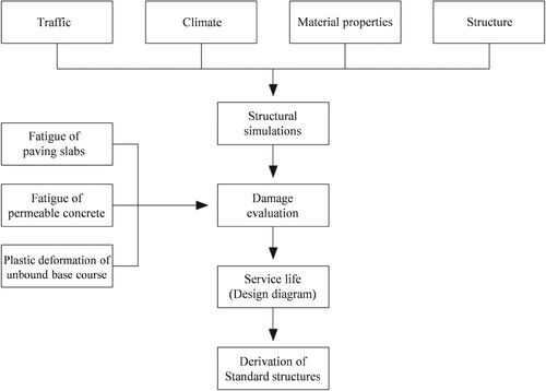
Besides traffic loading, the climate is a crucial factor that must be taken into consideration. Based on the season, the load-bearing capacity of the soil and the base layers is significantly depending on the temperature and on the amount and condition of stored water in the layers. As subgrade materials are only frost-proof in a few cases (Casagrande, Citation1936), the seasonal climatic fluctuations were considered by seasonally adjusting the E-Moduli of the soil and the lower base course according to the research in Litzka (Citation1987). Alongside the aforementioned external impact factors, the internal resistance factors like the structure and the used materials determine the durability and service life of the pavement.
With all boundary conditions defined, the structural simulations based on Füssl et al. (Citation2015) depict realistic conditions. Therefore, the numerical approach with the finite element program Abaqus allows the representation of realistic conditions using a radial area as load application. The material parameters for the concrete and granite slabs but also for the permeable concrete base layer were determined in laboratory tests (Eberhardsteiner et al., Citation2022).
The damage evaluation approach aims to assess relevant deterioration mechanisms, leading to design the structure on the serviceability limit state. According to the familiar design concept of the Eurocode, the resistance, here the maximum number of load changes that can be tolerated, must be greater than the effect of the exposure (ASI, Citation2013). On the one hand, the plastic deformation of the unbound base layer induced by vertical compression stress, and, on the other hand, the material fatigue of the paving slabs and permeable concrete base layer caused by the repeated cyclic load must be considered. Therefore, fatigue tests were conducted for the slabs and the pervious concrete base layer to obtain characteristic stress-load cycle curves (see Section 4). Since there is extensive research conducted for the plastic behaviour of unbound layers, damage criterions to assess the deterioration of the unbound lower base course were used from the literature (Shell, Citation1978).
With the results of the FEM simulation at hand (see Section 3), the stresses and deformations were used in the damage criterions to determine the tolerable number of life cycles for each layer. The shortest service life is decisive for the entire structure and is considered for the determination of the final load class.
3. Structural simulation
The aim of developing a structural model for the numerical simulation is to simulate the complex mechanical behaviour of the pavement. Based on the existing numerical simulations from Füssl et al. (Citation2015) the model was adapted with the below-mentioned parameters.
The plate geometry was varied regarding the plate thickness and format. Slabs with length-width ratios of 1:1, 1:1.5 and 1:2 and thicknesses of 8, 14 and 18 cm, respectively, were considered. In addition, structures with concrete and natural stone paving slabs were examined. Granite slabs were chosen as a typical representative of the group of natural stones due to their high availability and distribution in Austria. The upper base course was designed as a permeable concrete layer with all calculations being carried out for a base course layer thickness of 15 and 20 cm. Since the climatic and hydrological conditions have a decisive influence on the stiffness parameters of the unbound subgrade layers, four different bearing capacity periods were considered for all structures (FSV, Citation2018; Litzka, Citation1987). In total, 144 variants were investigated.
For modelling and calculating the different variants, the finite element program Abaqus CAE (Dassault Systèmes, Citation2015) was used. The model was specifically designed to capture the overall structural design realistically. For this purpose, a model measuring 6 × 6 m was created, with the format and thickness of the paving slabs being varied for each type of construction. Figure depicts details of the created model and its boundary conditions.
Figure 2. FE Model.
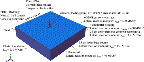
The centre of a slab, with a circular surface load and a radius r = 15 cm, was selected as the decisive load position. The amplitude of the load is 50 kN, resulting in a contact pressure of 0.707 MPa. This load represents the design load and acts simultaneously with the dead weight of the structure.
Each layer of the model is modelled with an elastic foundation in the side area. The lateral bedding reaction of the paving slabs is highest at 500 MN/m3, while the subsoil was rated the lowest at 40 MN/m3. Since not the entire soil, but only a 1-m-thick layer of the subsoil was modelled, an elastic bedding of 250 MN/m3 is also charged beneath the subsoil layer (Füssl et al., Citation2015). This model was validated in Blab et al. (Citation2012) and Füssl et al. (Citation2018).
Depending on the size and shape of the paving slabs, the distribution of forces in the structure is influenced. It is therefore important to define the mechanical interaction behaviour acting in the joints as realistic as possible, both in the vertical and in the horizontal direction. Therefore, a penalty contact algorithm from Füssl et al. (Citation2015) was used to model the anisotropic friction behaviour between the paving slabs in unbound joints. For bound construction, the interaction between the slabs and the mortar bed was described using the cohesive zone model (Song et al., Citation2006). The cohesive zone model is also used to describe the interaction in the joints between the plates (Hengl et al., Citation2018). All other layers are rigidly connected to one another. The material behaviour was assumed to be linear elastic and isotropic for all layers with the following material parameters listed in Table .
Table 1. Material parameters.
For discretisation, the model was split into several sub-areas with different hexagonal element sizes. The partitions were created with the aim of increasing the accuracy of the calculation in the loading area with a refined element size of 20 mm. Further afar from the loading point the element size gets larger in order to reduce the number of elements leading to an efficient computing time of seven minutes on average with converging accurate results.
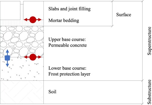
For the reason of pavement design, the bending stresses at the bottom of the slabs and at the bottom of the permeable concrete layer as well as the vertical strains at the top of the lower unbound base layer were analysed (see Figure ).
Figure 3. Relevant results from the FEM Simulations (square: plastic deformations; circle: stresses).
4. Damage evaluation
Prior to the finite element simulations, laboratory tests were conducted to determine the fatigue characteristics of the paving slabs and the permeable concrete base layer.
4.1. Fatigue of paving slabs
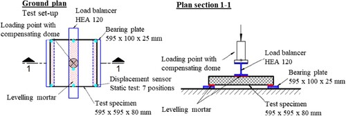
Original paving concrete and granite slabs with the dimensions 60 × 60 × 8 cm were selected. As the geometric dimensions of the tested slabs exceeded the size of usual fatigue test specimens (e.g. made of concrete), a new experimental setup had to be created (see Figure ). A test frame was chosen as the test device with which dynamic tensile and compression tests can be carried out. Dynamic tests were performed at a frequency of 8 Hz and with the following load amplitudes (three specimens each):
Series 01 – load level 5–15 kN
Series 02 – load level 5–20 kN
Series 03 – load level 5–25 kN
Figure 4. Sketch of the test setup for paving slabs.
Due to the constant lower force of 5 kN, the lower edge fibre of the test specimen stays always in the desired tensile swell area.
In addition, displacement sensors are attached to each specimen so that the deformation of the samples can be determined and the modulus of elasticity can be calculated. A point load is applied by the machine via a compensation dome, which prevents the occurrence of transverse forces. A load distributor in form of an HEA 120 steel profile is placed under the dome so that the punctual load acts as a uniform line load on the test specimen. To enable unhindered bending, two support plates made of 25 mm thick sheet steel were installed in the device. Since the paving slabs can have slight unevenness, a layer of levelling mortar was applied to the bearing slabs and under the load distributor before each test. The levelling layer is used to level the plates and the steel beam to ensure that the load is evenly applied. The tests can thus be referred to as three-point bending tests. A total of seven displacement transducers were tracking the movement of the specimen providing enough data to double-check the results.
During the fatigue tests, the number of load cycles with the associated time stamps, the minimum and maximum values of the applied force and the corresponding deflections are recorded. Although the main focus of the dynamic tests is on determining the maximum number of load cycles, the modulus of elasticity is also calculated. Since the conducted tests represent a three-point flexural tensile experiment and the recorded deflections clearly show the deformation of a system on two lateral bearing points, the Euler Bernoulli beam theory (Timošenko & Goodier Citation1970) can be applied for the evaluation of the material properties instead of the two-dimensional Kirchhoff–Love plate theory. As a result, the decrease in the Young’s modulus can be illustrated with an increasing number of load changes.
The tests were performed at 8 Hz, since concrete does not have a pronounced viscoelastic behaviour compared to asphalt, keeping the experiment within a feasible time range. Since a series contains several tests for a defined load level, the minima and maxima were given in Table in order to determine the stress amplitude range Δσslab. The specified interpolation function is used in a simplified representation as the fatigue criterion of the plates in the further course.
Table 2. Stress determination in the pavement concrete cross-section for the fatigue tests.
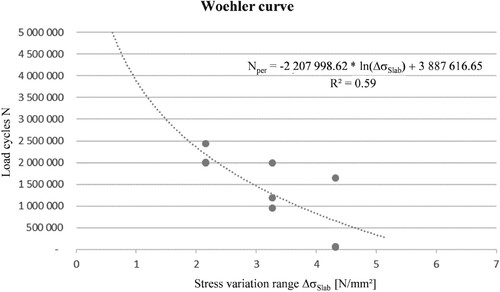
The fatigue curve for concrete paving slabs is exemplarily shown in Figure and represents a logarithmic interpolation curve. Although significantly more tests would be required to gain a better correlation between the experiments and the predicted results, it can nevertheless be stated that the figures match qualitatively and quantitatively with the curves described in different sources (AlShareedah et al., Citation2019; Chandrappa & Prapoorna, Citation2017; Chen et al., Citation2017). The depiction of the stresses Δσslab [N/mm2] on the abscissa and the number of load cycles on the ordinate does not correspond to the general representation of fatigue curves but was deliberately chosen because the stress values Δσslab determined are then used for the design of the paving structure and lead to a damage criterion of the form:
(1)
(1) where Δσslab [N/mm2] is the tensile bending strength on the bottom of the concrete slabs.
Figure 5. Fatigue curve for pavement concrete slabs.
Additionally, the size effect of six different slab geometries were analysed by performing bending tensile tests for concrete and granite specimen. Within the scope of the test accuracy of 10%, the results indicate with a low standard deviation of 2–5% that the size effect has no significant influence on the bending tensile strength. Therefore, all results are given for a maximum plate ratio of 1:2.
4.2. Fatigue of permeable concrete
For the permeable concrete, 1 × 1 × 0.20 m large slabs were tested to simulate the real-world conditions as close as possible. Due to the unusual specimen size, the fatigue behaviour of the material had to be tested on a new experimental setup. All four sides were supported on a metal frame while the cyclic compression load was applied for different stress levels. The detailed experimental setup and results can be found in Eberhardsteiner et al. (Citation2022). This study gives a fatigue criterion for permeable concrete of the form:
(2)
(2) where Δσpc [N/mm2] is the tensile bending strength on the bottom of the permeable concrete (pc) base course.
4.3. Fatigue of unbound lower base course material
In contrast to the material fatigue of paving slabs and permeable concrete, existing data from the literature was used to evaluate the plastic deformations for the unbound base course. The vertical strains at the top of the base layer obtained from FEM simulations were evaluated using the Shell-95%-criterion (Shell, Citation1978):
(3)
(3) where ϵzz [–] is the vertical strain at the top of the lower unbound base course and βBZ [–] is a constant factor dependent on the design reliability (here 95%).
5. Derivation of standard pavement construction
Analytical methods were used to derive standard pavement construction for bound slab pavements. These methods are primarily based on the computational determination of the relevant stress and strain values under given influences. Various numerical models, such as the finite element model described in Section 3, are available for calculating the primary effects.
These effects are linked to the possible number of load changes – and thus theoretically achievable service life of the construction – via empirical correlations (damage models). Fatigue, as a result of repeated exposure to dynamic loading (e.g. traffic), leads to the propagation of initial micro-cracks resulting in a decrease in stiffness (Suresh, Citation1998).
Corresponding fatigue criteria are cited in the literature (Heukelom & Klomp, Citation1962; Shell, Citation1978; Shook & Finn, Citation1982), which usually establish a connection between the relevant primary effects under traffic loads (stresses and strains) and the permissible number of load changes up to the fatigue of the layer (see also Section 4).
5.1. Design concept of current Austrian directive RVS 03.08.63
Within the current directive RVS 03.08.63 (FSV, Citation2016), recommendations regarding the pavement design in form of a design catalogue including standard pavement construction with paving stones and paving slabs made of natural stone or concrete are given. However, it currently only considers the unbound construction technique, which is regarded as the standard method. Depending on the traffic load, the material and the dimensions of the paving stones or slabs, minimum thicknesses are specified for the individual layers in order to guarantee a minimum load-bearing capacity.
The dimensioning takes place in several steps. First of all, the relevant traffic load must be determined in order to select a corresponding standard structure based on load classes. The catalogue of superstructures defines the minimum thicknesses of each layer to dissipate the stress that occurs during the specified period. To estimate the service life of a road pavement, the currently valid standard RVS 03.08.63 (FSV, Citation2016) compares the permissible and existing traffic loads on the basis of the allowable number of equivalent standard axle load repetitions. According to RVS 03.08.63 (FSV, Citation2016), four load classes are specified for paving stone and paving slab construction. For the choice of the load class, the traffic load of the most heavily loaded lane, the lane width and the number of lanes, are decisive. The relevant load traffic is referred to as the allowable number of equivalent standard axle load repetitions with a reference axle load of 100 kN. The determined number of equivalent standard axle load repetitions can then be assigned to a load class. The specified structures represent standardised designs for the corresponding load classes. The layer thicknesses should be considered as the required minimum thicknesses. Besides the obtained superstructures from the design catalogue, certain basic assumptions and approaches for the construction of a standardised road structure must be maintained:
In order to be able to use the layer thicknesses specified in the design catalogue, a deformation module of Ev1 ≥ 35 MN/m2 must be guaranteed for the sub-structure level. If necessary, this must be guaranteed by applying measures such as soil improvement or soil replacement.
As aforementioned, the climate and the hydrological condition significantly influences the bearing capacity of the soil. For the Austrian weather conditions, four annual periods can be distinguished (Litzka, Citation1987).
Specified minimum requirements regarding the load-bearing capacity and the degree of compaction of the unbound base course, called U-classes, can be found in the RVS 08.15.01 (FSV, Citation2017) and must be achieved. The requirements for a permeable concrete base course must comply with the RVS 08.18.01 (FSV, Citation2020).
The requirements for paving stone superstructures are regulated in RVS 08.18.01 (FSV, Citation2020). A distinction is made between building types with an unbound base layer (PF1 to PF3) and building types with a base layer made of permeable concrete (PF5 to PF7). The building types differ in the type of stone, the bond and the minimum stone thickness. The construction types PF4 with an unbound base course and PF8 with a base course made of pervious concrete contain paving slabs. The required minimum thicknesses of natural stone and concrete stone paving slabs for areas with heavy vehicles can be found in a design catalogue in RVS 03.08.63 (FSV, Citation2016). The prerequisite for using this catalogue is in compliance with the flexural strength of granite stone slabs of 10 N/mm2 (ÖNORM EN 12372; ASI, Citation2007b) and 5 N/mm2 for concrete stone slabs (ÖNORM EN 1339; ASI, Citation2007a). For the specified thicknesses, maximum aspect ratios of L / W ≤ 1.5 or 2, respectively, apply.
5.2. Derivation of new standard construction for bound paving slab structures with a base course made of permeable concrete
For the determination of standard construction for bound paving slab structures with a pervious concrete base layer, the fundamental methods used to derive the construction included in the design catalogue in the Austrian directive were used. The stress state of individual layers is determined using the FE model described in Section 3 and evaluated with the help of the fatigue criteria obtained in Section 4.
5.2.1. Damage assessment
Since the load-bearing capacity of the subsoil and thus the unbound layers above changes over the course of a year (Litzka, Citation1987), the stresses and strains for four subsoil load-bearing capacity periods were determined. The damages resulting in the individual layers were determined using the respective damage criterion as stated in Section 4, weighted according to the length of the periods and added up to a total damage (Miner Milton, Citation1945; Palmgren, Citation1924), to finally calculate the tolerable number of load changes. As a result, this number of load cycles is shown in the form of design diagrams as a function of the thickness of the permeable concrete base layer and the paving slabs as well as the type of material of the paving slabs.
The results of the dimensioning calculations for bound structures are summarised in Table for each layer. Thereby, the layer with the lowest tolerable number of load cycles (marked grey) is decisive and gives the tolerable number of load changes of the whole construction relevant for pavement design. Since the bound mortar bedding is designed to operate as a compound layer with the pervious concrete base course, the result of the individual layer is not significant.
Table 3. Decisive number of load cycles for the formation of load classes.
Empirical design parameters were considered in accordance with the standard construction given in the current design catalogue to ensure accordance with practical experience. The results are presented as design diagrams (see Figures and ). With the help of these diagrams, technically sound standards construction for load classes ranging from LC0.05 to LC1.3 can be derived. As mentioned in chapter 5.1, the load class (LC) defines the maximum permissible number of repetitions of the equivalent standard axle load (100 kN) per million transitions. In the following, the results are interpreted depending on the type of slab material and the thickness of the permeable concrete base layer. The recommended configurations are then summarised in a dimensioning table, similar to the design catalogue in RVS 03.08.63 (see Table ) (FSV, Citation2016).
Figure 6. Design diagram for concrete paving slabs with base layers made of permeable concrete with a thickness of 15 and 20 cm, respectively.
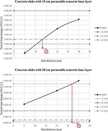
Table 4. Superstructure dimensioning catalogue.
Figure illustrates that the thickness of the permeable concrete base layer is essential for the structural service life. The upper limits of each load class are shown in grey tones, while the design results for the slab geometry 60 × 60 cm are shown in black. The intersection with the respective upper limit of each load class shows the minimum required plate thickness for the standard construction. For load class LC0.1, slabs with a minimum thickness of 12 cm are required for a 15 cm thick permeable concrete base layer. If the base layer is 20 cm thick, the load-bearing capacity increases. The maximum tolerable number of load changes increases and as a result, LC1.3 can be carried out with an 18 cm thick concrete paving slab.
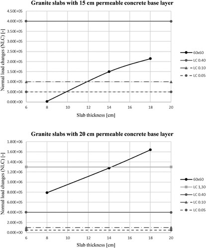
The design diagrams for granite paving slabs in Figure show similar results as for the concrete paving slabs. Due to the higher flexural strength of the granite stone slabs, thinner slab thicknesses can be realised. While a standard construction for LC1.3 requires at least 18 cm thick concrete paving slabs, the granite stone slabs can be executed with 16 cm thickness. A feasible recommendation for a design catalogue from all calculations is given in Table .
Figure 7. Design diagram for granite paving slabs with base layers made of permeable concrete with a thickness of 15 and 20 cm, respectively.
It is important to highlight that a full bond between slabs and bedding as well as bedding and permeable concrete base course is essential in order to ensure the calculated load-bearing capacity and, thus, avoid early deterioration of the system. The hydraulically bound mortar bedding and the joints must comply with the constructive requirements of the corresponding national standard (e.g. joint width, bedding thickness, mortar specifications). Insufficient compound or improper installation initiates cracks and the durability of the paving can be significantly reduced.
The bearing capacity, and hence the slab thickness, is almost independent of the slab format, assuming a force-fit connection between the paving slab and the bedding. The slab thickness can be reduced by 2–4 cm compared to unbound construction allowing slimmer superstructures where needed, while slab ratios of up to 1:2 can be realised. On the top end, standard construction for the load class LC1.3 is now available withstanding larger traffic loads.
The higher load-bearing capacity of the granite slabs also allows a reduction of 2 cm thickness in LC1.3 and LC0.4 compared to concrete slabs, providing even thinner superstructures.
6. Conclusion
This study successfully identified feasible standard constructions for rigid paving slabs with mortar-bound bedding and joints on a permeable concrete base course. Therefore, a new fatigue test setup for concrete and granite slabs was developed and used to determine a respective damage criterion. Results from bending tensile tests showed no significant size effect of different length to width ratios for both concrete and granite slabs. The induced stresses and deformations by the relevant traffic loads were determined using extensive finite element simulations. Hence, climatic and hydrological conditions influence the bearing capacity of the soil and the unbound materials, four seasonal periods were considered in the FE model. Based on the damage assessment and the decisive number of load cycles, design diagrams were created allowing the formation of standard construction for different load classes according to the design catalogue in the Austrian directive RVS 03.08.63.
Rigid paving slab structures with pervious concrete as base course allow for thinner and more durable superstructures compared to flexible unbound paving construction. Essential for the load-bearing behaviour is the tie between slabs, bedding and permeable concrete base course (e.g. mortar-bound bedding and joints). Without the compound effect, the superstructure cannot operate properly and early deterioration compromises the durability of the paving.
Acknowledgement
The authors also acknowledge TU Wien Bibliothek for financial support through its open access funding programme.
Disclosure statement
No potential conflict of interest was reported by the author(s).
Additional information
Funding
References
- AlShareedah, O., S Nassiri, S., & Dolan, J. D. (2019). Pervious concrete under flexural fatigue loading: Performance evaluation and model development. Construction & Building Materials, 207, 17–27. https://doi.org/10.1016/j.conbuildmat.2019.02.111
- Andersen, B., Bendtsen, H., Kragh, J., & Thomsen, S. N. (2007). Noise from streets with paving stones – paper for Inter.Noise 2007 in Istanbul. Road Directorate, Danish Road Institute.
- ASI. (2007a). ÖNORM EN 1339: Concrete paving flags – requirements and test methods.
- ASI. (2007b). ÖNORM EN 12372: Natural stone test methods – determination of flexural strength under concentrated load.
- ASI. (2013). ÖNORM EN 1990: Basis of structural design.
- ASI. (2020). ÖNORM B2214: Pavement works – contract to provide services.
- Autelitano, F., Garilli, E., & Giuliani, F. (2020). Criteria for the selection and design of joints for street pavements in natural stone. Construction and Building Materials, 259. https://doi.org/10.1016/j.conbuildmat.2020.119722
- Blab, R., Füssl, J., Gagliano, B., Hessmann, T., & Kluger-Eigl, W. (2013). Beiträge zur Weiterentwicklung von Pflasterbefestigungen. [Contributions to the further development of pavers] Mitteilungen Institut für Verkehrswissenschaften, Forschungsbereich Straßenwesen, Technische Universität Wien, 29. (in German).
- Blab, R., Kluger-Eigl, W., Füssl, J., Arraigada, M., & Hofko, B. (2012). Accelerated pavement testing on slab and block pavements using the new mobile load simulator MLS10. In 4th International Conference on Accelerated Pavement Testing, 19-Sep-2012–21-Sep-2012, Davis, California, USA. https://doi.org/10.1201/b13000-42
- Casagrande, L. (1936). Bodenmechanik und neuzeitlicher Straßenbau [Soil mechanics and modern road construction]. Volk u. Reich Verl. https://permalink.catalogplus.tuwien.at/AC06029853 (in German)
- Chandrappa, A. B., & Prapoorna, K. (2017). Flexural-fatigue characteristics of pervious concrete: Statistical distributions and model development. Construction and Building Materials, 153, 1–14. https://doi.org/10.1016/j.conbuildmat.2017.07.081.
- Chen, X., Fan, J. B. X., Lu, J., & Xu, L. (2017). Effect of loading frequency and stress level on low cycle fatigue behavior of plain concrete in direct tension. Construction & Building Materials, 133, 367–375. https://doi.org/10.1016/j.conbuildmat.2016.12.085
- Dassault Systèmes. (2015). Abaqus/CAE 2016 (version build ID: 2015_09_24-22.31.09 126547). Dassault Systèmes Simulia Corp.
- Eberhardsteiner, L., Roth, S., Oltra, J., & Blab, R. (2022). Fatigue behaviour of permeable concrete used as base layer for block pavements. Submitted to Materials and Structures.
- FQP. (2012). Pflasterer Handwerkerbuch. Grundlagen für den Beruf des Pflasterers [Pavers craftsman book. Basics for the profession of pavers] (Vol. 1). Jugend&Volk. (in German).
- FSV. (2016). RVS 03.08.63: Pavement design. Austrian Research Association for Roads, Railways and Transport. (in German).
- FSV. (2017). RVS 08.15.01: Unbound base layers. Austrian Research Association for Roads, Railways and Transport. (in German).
- FSV. (2018). RVS 03.08.68 Mechanistic asphalt pavement design. Austrian Research Association for Roads, Railways and Transport.
- FSV. (2020). RVS 08.18.01 Block pavings and slab pavings: Edgings. Austrian Research Association for Roads, Railways and Transport. (in German).
- Füssl, J., Hengl, H., Eberhardsteiner, L., Kluger-Eigl, W., & Blab, R. (2018). Numerical simulation tool for paving block structures assessed by means of full-scale accelerated pavement tests. International Journal of Pavement Engineering, 19(10), 917–929. https://doi.org/10.1080/10298436.2016.1224410
- Füssl, J., Kluger-Eigl, W., Eberhardsteiner, L., & Blab, R. (2015). Mechanical performance of pavement structures with paving slabs – part II: Numerical simulation tool validated by means of full-scale accelerated tests. Engineering Structures, 98, 221–229. https://doi.org/10.1016/j.engstruct.2014.10.055
- Garilli, E., & Giuliani, F. (2019). Stone pavement materials and construction methods in Europe and North America between the 19th and 20th century. International Journal of Architectural Heritage, 13(5), 742–768. https://doi.org/10.1080/15583058.2018.1470269
- Hengl, H. L., Kluger-Eigl, W., Blab, R., & Füssl, J. (2018). The performance of paving block structures with mortar filled joints under temperature loading, accessed by means of numerical simulations. Road Materials and Pavement Design, 19(7), 1575–1594. https://doi.org/10.1080/14680629.2017.1330221
- Hensel, H.-D. (2007, June 1). Paving design: Is rigid-fix external stone paving the way to go? Journal of ASTM International, 4(6), 1–14. https://doi.org/10.1520/JAI100843.
- Heukelom, W., & Klomp, A. (1962). Dynamic Testing as a Means of Controlling Pavement during and after Construction. In Proceedings of the 1st International Conference on the Structural Design of Asphalt Pavement, Ann Arbor, MI, 20–24 August, 667–685.
- Litzka, J. (1987). Die Bemessung des Straßenoberbaus nach der neuen RVS 3.63 [Design of the road pavement according to the new RVS 3.63] (Vol. Heft 2). Baumaschine, Baugerät, Baustelle. (in German).
- Michel, D. (2006). Thematic strategy on air pollution and on the proposal for a directive of the European Parliament and of the Council on ambient air quality and cleaner air for Europe. Official Journal of the European Union 1–4.
- Miner Milton, A. (1945). Cumulative damage in fatigue. Journal of Applied Mechanics, 12(3), A159–A164. https://doi.org/10.1115/1.4009458
- Murat Algin, H. (2007). Interlock mechanism of concrete block pavements. Journal of Transportation Engineering, 133(5), 318–326. https://doi.org/10.1061/(ASCE)0733-947X(2007)133:5(318)
- Palmgren, A. (1924). Die Lebensdauer von Kugellagern. [The service life of ball bearings]. VDI-Zeitschrift, 68, 339–341. (in German).
- Sandberg, U. (2001). Tyre/road noise: myths and realities (No. 1102626X (ISSN). In Proceedings of The 2001 International Congress and Exhibition on Noise Control Engineering, The Hague, The Netherlands, 2001 August 27–30, http://urn.kb.se/resolve?urn=urn:nbn:se:vti:diva-4864
- Sandberg, U., Bendtsen, H., Thomsen, S. N., Kragh, J., Kalman, B., & Kokot, D. (2007). Possibilities to reduce tyre/road noise emission on paving stones and other block surfaces. European Commission DG research “silence”. European Commission DG Research Sixth Framework Programme Priority 6 Sustainable Development, Global Change & Ecosystems Integrated Project – Contract N. 516288. 516288 .
- Shell. (1978). Shell pavement design manual. Shell International Petroleum Company Limited.
- Shook, J., & Finn, F. (1982). Thickness design of asphalt pavements. Proc. of the 5th International International Conference on the Structural Design of Asphalt Pavements.
- Song, S. H., Paulino, G. H., & Buttlar, W. G. (2006). A bilinear cohesive zone model tailored for fracture of asphalt concrete considering viscoelastic bulk material. Engineering Fracture Mechanics, 73(18), 2829–2848. https://doi.org/10.1016/j.engfracmech.2006.04.030
- Suresh, S. (1998). Fatigue of materials (2nd ed.). Cambridge University Press. https://doi.org/10.1017/CBO9780511806575
- Timošenko, S. P., and Goodier J. N. (1970). Theory of elasticity (3rd. ed). McGraw-Hill.
- Westergaard, H. M. (1926). Stresses in concrete pavements computed by theoretical analysis. Public Roads, 7, 25–35.