
ABSTRACT
A major challenge in computation of engineering flows is to derive and improve turbulence models built on turbulence physics. Here, we present a physics-based modified k–ω equation for canonical wall-bounded turbulent flows (boundary layer, channel and pipe), predicting both mean velocity profile (MVP) and streamwise mean kinetic energy profile (SMKP) with high accuracy over a wide range of Reynolds number (Re). The result builds on a multi-layer quantification of wall flows, which allows a significant modification of the k–ω equation. Three innovations are introduced: first, an adjustment of the Karman constant to 0.45 is set for the overlap region with a logarithmic MVP; second, a wake parameter models the turbulent transport near the centreline; third, an anomalous dissipation factor represents the effect of a meso-layer in the overlap region. Then, a highly accurate (above 99%) prediction of MVPs is obtained in Princeton pipes, improving the original model prediction by up to 10%. Moreover, the entire SMKP, including the newly observed outer peak, is predicted. With a slight change of the wake parameter, the model also yields accurate predictions for channels and boundary layers.
1. Introduction
Prediction of canonical wall-bounded turbulent flows is of great importance for both theoretical study and engineering applications [Citation1]. They are the fundamental problems of turbulence often benchmarked to validate computational fluid dynamics (CFD) models. One example is the celebrated log-law, an essential part of the Reynolds-averaged Navier–Stokes (RANS) simulations of engineering flows [Citation2,Citation3]. Despite extensive studies over several decades, simultaneously, accurate predictions of both the mean velocity and fluctuation intensities still remain as an outstanding problem [Citation4]. One challenge concerns the universality (or not) of the Karman constant κ [Citation5]. Spalart [Citation6] asserts that a difference of 6% in κ can change the predicted skin friction coefficient by up to 2% at a length Reynolds number of 108 of a typical Boeing 747. On the other hand, more than 10% variation of κ is reported in the literature [Citation4]. One of the major uncertainties in measuring κ is due to the arbitrary definition of the overlap region at finite Re's [Citation7,Citation8]. Taking the Princeton pipe data for example, while Zagarola et al. [Citation9] choose an overlap region between 600 < y+ < 0.07Reτ, yielding κ = 0.436, Mckeon et al. [Citation10] choose the region between 600 < y+ < 0.12Reτ, yielding κ = 0.421. Recently, Marusic et al. [Citation11] define an overlap region in y+ between and
(where the streamwise kinetic energy also exhibits a logarithmic profile), and suggest κ to be 0.39 for Princeton pipe data. Therefore, different settings of overlap region obviously lead to different values of κ, which are under vivid debates. In fact, the κ values show no sign of convergence, varying over a fairly wide range [Citation4,Citation7,Citation8]. Another recent effort by Nagib et al. [Citation12] involves determining κ by composing the whole profile with matched asymptotic expansions. With their assumed Pade approximations, more than 10 adjustable parameters are introduced to describe the mean velocity profile (MVP) for channel, pipe and TBL flows, and the set of parameters for channel differs significantly from those for pipe and turbulent boundary layer (TBL), with no physical explanation of the parameters. They even suggested ‘Karman coefficient’ instead of Karman constant [Citation12–14]. In this work, we carry out a careful comparison to illustrate what optimal κ should be used in the k–ω model. Based on our results [Citation15,Citation16], we have determined a flow-dependent bulk flow structure, thus removing the need for an ill-defined overlap region. Our theory thus defines κ as a global coefficient based on the entire outer flow, which coincides with von Karman's original definition using an overlap region for asymptotically large Re. Here we apply this new κ (=0.45) and show it leads to improved predictions of the k–ω model.
Another challenge is the outer peak of the SMKP (or streamwise fluctuation intensity), not predicted by existing turbulence models. Some prior models (e.g. the k–ω model) assume a Bradshaw-like constant which yields an equilibrium state where turbulent fluctuations reach a constant plateau in the overlap region [Citation17]. However, this is against recent accurate measurements [Citation18–20]. Unlike studies on the MVP [Citation21–24], theoretical works on the SMKP are much fewer. The logarithmic scaling by Townsend [Citation25] and Perry et al. [Citation26] are only observed recently, and the composite description of SMKP through piece-wise functions [Citation27–31] is difficult to incorporate in the RANS models. Hence, improvement of the SMKP prediction is more subtle.
In this paper, we present a modified k–ω model which shows the improvement of predictions of both MVP and SMKP based on the understanding of multi-layer physics of wall turbulence. The k–ω model is widely used in engineering applications, enabling predictions of both the mean and fluctuation velocities. Here, we introduce three modifications to the latest version of the model by Wilcox (2006) [Citation17]: (1) an adjustment of the Karman constant, (2) a wake parameter to take into account the enhanced turbulent transport effect, and (3) an anomalous dissipation factor to represent a meso-layer in the overlap region. These modifications yield a more accurate (above 99%) description of MVPs in Princeton pipe data for a wide range of Re's, improving the Wilcox k–ω model prediction by up to 10%. Moreover, they yield a good prediction of the entire SMKP, where the newly observed outer peak [Citation18] is also captured. With a slight change of the wake parameter, the model yields also very good predictions for turbulent channels and TBLs.
The paper is organised as follows. Section 2 introduces the predictions by original k–ω equation as well as its approximate solutions in the overlap region. In Section 3, we present two of the three modifications mentioned above and compare with empirical MVP data. Section 4 introduces the third modification for prediction of SMKP. Conclusion and discussion are presented in Section 5.
2. The original k–ω equation's predictions
In 1942, Kolmogorov [Citation32] introduced a closure for turbulent kinetic energy k through the dissipation rate ε, via ω = ε/k. As the dimension of ε is [ℓ]2[t]−3, the dimension for ω is [t]−1, which is interpreted as the energy cascade rate. Kolmogorov suggested a transport equation for ω, parallel to that for k. Independent of Kolmogorov, Saffman [Citation33] also formulated a k–ω model, and since then, a further development and application of k–ω model has been pursued [Citation34,Citation35]. The latest version established by Wilcox [Citation17] reads
(1)
(2) In (Equation1
(1) ) and (Equation2
(2) ), the right-hand side (r.h.s.) is production, dissipation, viscous diffusion and turbulent transport in order, and there is an additional cross-diffusion term in (Equation2
(2) ). In its original version, k denotes the total kinetic energy – sum of streamwise, wall normal and spanwise components. As noted by Wilcox [Citation35], it is not critically important whether k is taken to be the full kinetic energy of these components or, alternatively, the streamwise component only. The rationale is that in both cases, the quantity k represents a measure of fluctuation intensity. In what follows, we assume that k = ⟨u′u′⟩/2, because in parallel flows such as in pipe or in channel, (Equation1
(1) ) is more similar to the budget equation of ⟨u′u′⟩/2, than to that of the other two components (spanwise and normal). In other words, the production of the SMKP is by mean shear, in contrast to the spanwise and normal fluctuation intensities by pressure-strain. Note that this does not necessarily mean that the equation for ⟨u′u′⟩/2 is exactly the same as that for the total kinetic energy. In fact, there is a difference between the two, e.g., it is the pressure-strain term in former – different from the pressure-transport term in the latter – redistributing the energy to wall normal and spanwise directions (prominent in the buffer layer). However, as we focus on the predictions of ⟨u′u′⟩, such a difference is ignored and we still introduce the eddy viscosity to approximate the pressure-strain effect. We use data to validate this assumption. As we show below, our definition of k with appropriate modifications (for turbulent transports) indeed yields good predictions to recent experiments of pipe and channel.
Consider the fully developed channel flow, for example. The left-hand side (l.h.s.) of (Equation1(1) ) and (Equation2
(2) ) is all zero. The two equations are coupled with the streamwise mean momentum equation (mean velocities in the wall normal y and spanwise z directions are zero), which, after integration once in y, reads
(3) where
is the friction velocity, δ is the channel half width. For convenience, y will designate y/δ in the remainder of this paper unless otherwise specified. Introducing the viscous normalisation (using velocity scale uτ and length scale ν/uτ) indicated by super script +, all the above equations are nondimensionalised as
(4)
(5)
(6) where S+ = dU+/dy+ (we change partial derivative to ordinary derivative since only y dependence is considered here); W+ = −⟨u′v′⟩+; and 1 − y+/Reτ = r is the normalised distance from the centreline.
Note that for pipes, cylindrical coordinates are more convenient. In this case, the mean momentum equation is the same as (Equation6(6) ) (see Appendix 1), but the k and ω equations are
(7)
(8) Only the diffusion and transport terms are modified in pipes compared to channels, introducing a slightly higher mean velocity in the bulk of pipes at the same Reτ.
The mean quantities of a TBL follow a two-dimensional equation with a streamwise development. However, in this paper, we only consider the description of the streamwise MVP and SMKP for a given Reτ. For the k–ω model of TBL, the Cartesian coordinates are used as in channels.
Note that the k–ω equation defines the eddy viscosity as
(9) Thus, (Equation4
(4) )–(Equation9
(9) ) are a set of closed equations to predict both MVP and SMKP. The (complicated) parameter setting in the original k–ω equation [Citation17] is as follows:
,
and
are functions of y+, with Rk = 6, Rω = 2.61 and Rβ = 8, indicating the specific transition locations of α*, α and β*, respectively. Other coefficients are constants, i.e. α∞ = 0.52; α*0 = β0/3; α0 = 1/9; β*0 = 0.09; β = β0 = 0.0708; σ = 0.5; σ* = 0.6; σd = 0.125.
2.1. Approximate solutions in the overlap region
Before we display the numerical result of the k–ω equation, it is important to discuss the approximate solutions in the overlap region, in order to reveal the role of κ. These local solutions, also obtained in [Citation17], help us to understand the difference between numerical result and empirical data, and to suggest plausible improvement, as shown below.
At first, let us present a general expression for mean shear and kinetic energy in the outer flow (including the overlap and wake or central core regions). In this region, the mean shear S+ is much smaller than the Reynolds shear stress W+, and we have W+ ≈ r in (Equation6(6) ). Therefore, S+ is given as
(10) In the k-equation (Equation1
(1) ), we further introduce a ratio function between dissipation and production, i.e. Θν = ϵ+k/(S+W+) = β*k+ω+/(S+W+), which gives the leading balance transition. It follows that Θν ≈ β*k+ω+ν+T/r2 by substituting (Equation10
(10) ) in, which, together with ω+ν+T = α*k+, leads to the solution
(11)
Furthermore, (approximate) analytical solutions can be derived specifically in the overlap layer, i.e. for y+ varying from 40 to 0.1Reτ (exact values of the bounds do not affect the analysis below). In this layer, W+ ≈ r ≈ 1 (for large Reτ), α* ≈ 1, α ≈ α∞, β ≈ β0, β* ≈ β*0, Θν ≈ 1 (the quasi-balance between production and dissipation in (Equation7(7) )). Therefore, (Equation11
(11) ) tells us
(12) and hence ⟨u′u′⟩+ = 2k+ ≈ 6.6. Note that k+/W+ ≈ 3.3 is a Bradshaw-like constant.
Moreover, (Equation10(10) ) yields ν+T ≈ 1/S+; from (Equation9
(9) ) and (Equation12
(12) ),
. Substituting these two results into (Equation8
(8) ) yields
(13) (note that the diffusion- and stress-limited terms are much smaller and hence neglected). The above equation owns an analytical solution
(14) with the Karman constant determined by four model coefficients:
(15) With α∞ = 0.52, β0 = 0.0708, β*0 = 0.09, σ = 0.5 as Wilcox originally suggested, the resulting κ in (Equation15
(15) ) is 0.40. Also note that the log-law additive constant B is about 5.6 if κ = 0.40.
Therefore, k–ω ensures a log-profile for the mean velocity and a constant kinetic energy in the overlap region. However, these two solutions depart significantly from data (shown below), and their modifications are the main results of this paper.
2.2. Numerical results of the original k–ω equation
We use the numerical code presented in [Citation17] to calculate the above k–ω equation. Note that a central difference scheme is used, and the grid is set to guarantee that there are at least 10 points below y+ = 1. A logarithmic mean velocity with a constant kinetic energy is used as the initial solution for iteration, and the convergence condition following that used in [Citation17] is set as |Un+1 − Un| ≤ 1 × 10⁻⁵ where n denotes the number of iterations. Below, the k–ω equation (model) indicates the Wilcox (2006) version, while k–ω SED [Citation36] indicates the modified one unless otherwise specified.
The numerical solution of MVPs by the k−ω model, i.e. (Equation6(6) )–(Equation9
(9) ), is shown in , compared with Princeton pipe data [Citation9] at Reτ = 42,156 and 528,550. Note that the deviation in the outer region is significant, especially for Reτ = 528550, with overprediction of the mean velocity everywhere. Note also an unphysical feature of this model: the predicted MVP near the centreline is lower than the initial log-profile, whereas the empirical data always show a wake structure higher than the log-profile. We thus propose two modifications of the k−ω model: reset Karman constant to 0.45, and add a wake correction enhancing the turbulent transport, where a much better prediction is achieved ().
Figure 1. Comparison of the MVP prediction by the Wilcox k−ω model (dashed line) with Princeton pipe measurements [Citation9] (symbols) at Reτ = 42,156 (a) and 528,550 (b). The dash-dotted line indicates our prediction by changing Karman constant 0.40 into 0.45, which show a clear improvement in the overlap region. The solid line is the prediction of the modified k−ω model discussed in Section 3.
![Figure 1. Comparison of the MVP prediction by the Wilcox k−ω model (dashed line) with Princeton pipe measurements [Citation9] (symbols) at Reτ = 42,156 (a) and 528,550 (b). The dash-dotted line indicates our prediction by changing Karman constant 0.40 into 0.45, which show a clear improvement in the overlap region. The solid line is the prediction of the modified k−ω model discussed in Section 3.](/cms/asset/9c16ca24-2bac-492c-bd38-6671f4d8e029/tjot_a_1243244_f0001_c.jpg)
For SMKP, the result is shown in . Note that we choose two recent profiles from Princeton pipe [Citation18] at Reτ = 68,371 and 98,187, where the outer peak and the approximate logarithmic profile in the bulk flow region are observed, i.e.
Figure 2. SMKP prediction by the Wilcox k−ω model (dashed line) compared with Princeton pipe measurements [Citation18] (symbols) at Reτ =68,371 (a) and 98,187 (b). The dash-dotted line indicates the logarithmic profile in (Equation16(16) ), and the solid line is the prediction of our modified k−ω model discussed in Section 4.
![Figure 2. SMKP prediction by the Wilcox k−ω model (dashed line) compared with Princeton pipe measurements [Citation18] (symbols) at Reτ =68,371 (a) and 98,187 (b). The dash-dotted line indicates the logarithmic profile in (Equation16(16) ), and the solid line is the prediction of our modified k−ω model discussed in Section 4.](/cms/asset/e43695c5-e014-492a-81a1-6bcb33928784/tjot_a_1243244_f0002_c.jpg)
3. Modification of the k−ω equation for MVP
First, we observe that the k−ω model overpredicts MVP compared with Princeton pipe data as shown in . The slope of the dashed line is larger than the slope of the Princeton pipe data in the region between y+ = 103 and y+ = 104, suggesting that we need to increase the value of κ in the k–ω equation. Thus, our first attempt is to increase κ from 0.4 to 0.45 (according to [Citation15,Citation16]); and a higher B. A specific choice is to increase α∞ from 0.52 to 0.57 for increasing B; and to set by following (Equation15
(15) ) to guarantee κ = 0.45. This amounts to adjusting only two parameters (α∞ and σ) to obtain desired κ and B. The reason we choose to adjust α∞ and σ, instead of β in (Equation15
(15) ), is that the latter affects both MVP and SMKP. Indeed, this simple modification yields a very promising result, as shown in (dash-dotted lines), which significantly improves the description of the overlap region.
Inspecting the outcome in , the second deficiency of the original k–ω model becomes more pronounced: approaching the centreline, the MVP prediction of the k−ω equation increases too slowly, even below the log-profile, contrary to the trend shown in empirical data. To rectify this deficiency, an approximate analytical solution of the k−ω equation for the entire outer flow becomes helpful (see below).
3.1. Outer similarity
To rectify the deficient wake structure of the k–ω equation, the analysis of the overlap region is too restricted, and we must derive a new set of approximate balance equations valid for the entire outer flow – including the effects of turbulent transport which plays the dominant role in the central core region. In fact, this is possible since we have the following analytical expression for the entire outer flow region, k+ ≈ ν+Tω+, S+ ≈ r/ν+T. Substituting them back into (Equation7(7) ) and (Equation8
(8) ), only neglecting the diffusion terms, we obtain
(17)
(18) where
and
are normalised to eliminate the Re effect in the outer flow. In other words, by changing the primary variables (k+ and S+) into νT and ω, we obtain a (closed) set of invariant equations for the outer flow.
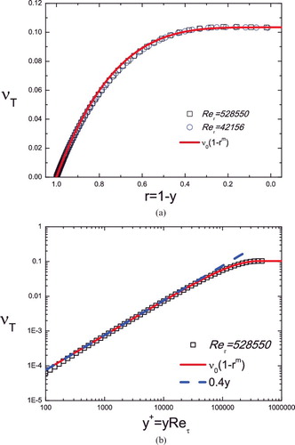
Indeed, this self-similarity is validated as shown in which displays a full collapse of νT profiles for Reτ = 42,158 and 528,550. Note that as νT determines the mean shear and hence MVP, it is important to pursue an approximate analytical description of νT for the entire outer flow. It turns out that νT satisfies a specific ansatz
(19) explained as below. Note that (Equation19
(19) ) displays two local states, i.e. νT → ν0 as r → 0 and νT → ν0m(1 − r) = ν0my → 0 as r → 1 (y = 1 − r → 0), the latter being the approximate solution in the overlap region. Here, ν0 is the centreline eddy viscosity and m is the defect power law scaling exponent. According to data in , ν0 ≈ 0.103 (independent of Re), which determines the scaling exponent: m = κ/ν0 ≈ 0.40/0.103 ≈ 3.88. This amounts to a matching with the logarithmic solution νT = κy. With only one empirical coefficient (i.e. ν0), (Equation19
(19) ) is shown to be in excellent agreement with the full numerical solution of the original k–ω equation, as illustrated in . Incidentally, by substituting (Equation19
(19) ) into (Equation17
(17) ) or (Equation18
(18) ), one obtains a nonlinear (second-order) ordinary differential equation for ω, which is deferred as we here focus on the description of the MVP.
Figure 3. Validation of the bulk solution ansatz (Equation19(19) ) (solid line) for the eddy viscosity in the Wilcox k−ω model by its full numerical solution (symbols). (a) In centre coordinate, r = 1 − y. (b) In wall coordinate,
. Note that the numerical profiles collapse for two very different Re's, indicating self-similarity for the eddy viscosity in the outer flow. Dashed line indicates the near-wall linear scaling νT = κy.
3.2. Modification taking into account the effects of turbulent transport
Now, we introduce the wake modification. The essence is to enhance the turbulent transport effect, hence to decrease the eddy viscosity function towards the wake flow region that would lead to an increment of MVP. Since the original k–ω model is good at small y, and νT is generally an increasing function of y, a schema to enhance the effect of turbulent transport at large y is to introduce a nonlinear dependence of σ* and σ on νT such that when νT becomes large (close to the centreline), a new term representing the effect of turbulent transport becomes more significant over the original setting. Specifically, we assume
(20) Under this assumption, the outer similarity equations (Equation17
(17) ) and (Equation18
(18) ) for pipe read
(21)
(22) Note that we have eliminated the cross-diffusion term in the ω equation (Equation18
(18) ) (i.e. σd = 0) as it is unphysical here. Moreover, the rationality of (Equation20
(20) ) can be further explained as follows. When γ = 0, Equations (21) and (22) go back to the original k–ω equation; when γ > 0, the nonlinear term is very small in the overlap region where νT ≈ κy → 0, but becomes order one if γν0 is of order one for increasing y (or decreasing r) close to the centreline (r → 0) with
. This yields an estimate γ ∼ 1/ν0 (a specific value of γ will be given below). Note that the quadratic term γ2ν2T in σSED and σ*SED maintains the outer similarity of (Equation21
(21) ) and (Equation22
(22) ) as the original k–ω equation does. Note also that an earlier attempt to use a linear correction term (γνT) in (Equation20
(20) ) yields a qualitatively similar result, but quantitatively not as good as the quadratic term. At this point, we cannot show that the modification schema is unique, but the current choice in (Equation20
(20) ) seems to be the simplest option to give rise to a satisfactory outcome.
Substituting (Equation20(20) ) into (Equation7
(7) ) and (Equation8
(8) ), we obtain a set of modified k–ω equations, which include
(23)
(24) where σ*SED/σ* = σSED/σ = 1 + (γν+T/Reτ)2. The three equations (e.g. (Equation9
(9) ), (Equation23
(23) ) and (Equation24
(24) )) form a new closed system for the prediction of MVP in a turbulent pipe flow, on which the comparisons reported in the next subsections are based.
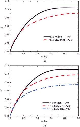
It is important to check if the model (Equation20(20) ) with a quadratic nonlinearity decreases the eddy viscosity towards centreline. The results are shown in . Compared to , the model (Equation20
(20) ) yields a smaller ν0 ≈ 0.091. This decrease yields a larger mean shear near the centreline, and hence a bigger increment and a stronger wake correction away from the logarithmic profile in the mean velocity, which is required to rectify the deficiency in the original k–ω model. Note that γ is the only parameter to be determined and is found to be 25 for pipe flows, independent of Re, which is close to 1/ν0 (noting that γν0 ≈ 2.3). Since γ determines the amount of velocity increment beyond the log-profile, it is considered to be similar to the Coles wake parameter [Citation37]. Our analysis here relates γ to ν0, which we believe is one of the important constants in fully developed pipe turbulence. To know the exact relation between γ and ν0, it needs further investigation with more general consideration of the nonlinear eddy viscosity correction term.
Figure 4. Validation of eddy viscosity. (a) Pipe. Solid line: original k–ω model with γ = 0; dashed line: modified model with γ = 25. (b) Channel and TBL. Solid line: original k–ω model for channel; dashed line: modified model with γ = 20 for channel; dash-dotted line: modified model with γ = 40 for TBL.
3.3. Validation of the MVP prediction by the modified k–ω equation
The modified k−ω model with κ = 0.45 (i.e. α∞ = 0.57 and σ = 0.488) and γ = 25 (the only extra parameter) yields a significant improvement of the prediction of the MVP for turbulent pipe. (a) shows the comparison of the numerical solutions of MVPs of the modified k−ω model equations with empirical data by Zagarola and Smits [Citation9] at 10 different Re's; they are all in excellent agreement. The relative errors, displayed in (b), are uniformly bounded within 1% – significantly smaller than that of the original k−ω model, which shows a trend of increase with increasing Re, and goes up to 6%.
Figure 5. (a) Predictions of the modified k−ω model (lines) compared with Princeton pipe data by Zagarola and Smits [Citation9] for 10 MVPs. Profiles are staggered vertically for a better display. (b) The relative errors, (UEXP/UModel − 1) × 100% of the modified k−ω model (with κ = 0.45) (solid symbols), are bounded within 1%. Also included is the Wilcox k−ω model (κ = 0.40, open symbols), showing a 6% relative error at the largest Re.
![Figure 5. (a) Predictions of the modified k−ω model (lines) compared with Princeton pipe data by Zagarola and Smits [Citation9] for 10 MVPs. Profiles are staggered vertically for a better display. (b) The relative errors, (UEXP/UModel − 1) × 100% of the modified k−ω model (with κ = 0.45) (solid symbols), are bounded within 1%. Also included is the Wilcox k−ω model (κ = 0.40, open symbols), showing a 6% relative error at the largest Re.](/cms/asset/bf038acc-ae30-4239-a1b0-3ae0c65e396a/tjot_a_1243244_f0005_c.jpg)
We have also compared the predictions with data by McKeon et al. [Citation10], keeping the same κ = 0.45 and γ = 25. The results ((a)) are also in good agreement, with relative errors bounded within 1% ((b)), while the original k−ω model overpredicts by 5% (not shown). Note that the largest deviations are about 2% for the first few measurement points at high Re's, close to experimental uncertainty. Incidentally, more recent MVP data by Hultmark et al. [Citation18] show noticeable deviations from earlier MVP data in [Citation9] and [Citation10]; and our study shows that κ ≈ 0.42 gives a satisfactory description of the MVP data in [Citation18]. Particular explanation for this deviation (due to different data uncertainty) is not apparent and not discussed here.
Figure 6. (a) Comparison of the predictions of the modified k−ω model (lines) with Princeton pipe data by McKeon et al. [Citation10] for 10 MVPs. Each profile is staggered vertically for a better display. (b) The relative errors of the modified k−ω model (solid symbols) are mostly bounded within 1%.
![Figure 6. (a) Comparison of the predictions of the modified k−ω model (lines) with Princeton pipe data by McKeon et al. [Citation10] for 10 MVPs. Each profile is staggered vertically for a better display. (b) The relative errors of the modified k−ω model (solid symbols) are mostly bounded within 1%.](/cms/asset/91836c08-0cc0-4ad8-ab43-e4aa0ded6f7b/tjot_a_1243244_f0006_c.jpg)
Moreover, we present the comparison of our predictions with DNS pipe data by Wu and Moin [Citation38] at Reτ = 1142 and by Ahn et al. [Citation39] at Reτ = 3008. Note that compared to numerous Princeton pipe experiments, the DNS pipe data are much fewer and the Re's are much lower. The latter results in a highly restricted ‘overlap region’ where a clear overlap region cannot be defined – according to the criteria set by Zagarola and Smits [Citation9] (between 600 < y+ < 0.07Reτ), or by McKeon et al. [Citation10] (between 600 < y+ < 0.12Reτ), or by Marusic et al. [Citation11] (where k also exhibits logarithmic scaling). In spite of this constraint, the major improvement of our MVPs results from the fact that the entire core region is considered in our approach to select κ. This is demonstrated in , where our modified k–ω equation gives a better prediction than the original k–ω equation, particularly for the outer flow region (errors around 2%). For y+ < 100, the two models’ predictions are indistinguishable (both are lower than the DNS data in the region 10 < y+ < 100), as our modifications focus on the outer flow. Thus, the new k–ω model presents reasonably good description of DNS data.
Figure 7. Comparison of the MVP prediction by the Wilcox k−ω model (dashed line) and modified model (solid line) for DNS pipe (symbols) at Reτ = 1142 by Wu and Moin [Citation38] (a) and at Reτ = 3008 by Ahn et al. [Citation39] (b). Inset shows the relative errors 100 × (1 − UDNS/UTheory), where ours (open symbols) are within 2% compared to 6% by the original k–ω model (solid symbols) for y+ > 100.
![Figure 7. Comparison of the MVP prediction by the Wilcox k−ω model (dashed line) and modified model (solid line) for DNS pipe (symbols) at Reτ = 1142 by Wu and Moin [Citation38] (a) and at Reτ = 3008 by Ahn et al. [Citation39] (b). Inset shows the relative errors 100 × (1 − UDNS/UTheory), where ours (open symbols) are within 2% compared to 6% by the original k–ω model (solid symbols) for y+ > 100.](/cms/asset/7ff5c844-674e-426a-960e-e9d28ce2f5e9/tjot_a_1243244_f0007_c.jpg)
(a) shows the comparison of two integral quantities of engineering interest, the centreline velocity U+c and the volume-averaged mean flux , for Reτ from 5000 to 528, 550. The modified k–ω model (solid lines) improves significantly the original k–ω model (dashed lines), which is clearly demonstrated by the plot of the relative errors in (b). Note that the systematic bias of the original k–ω model reflects a too small κ used in the original k–ω model.
Figure 8. (a) Predictions of the centreline velocity (square) and the volume-averaged mean flux (circle) of the Wilcox (dashed lines) and modified (solid lines) k−ω models compared with Princeton pipe data [Citation9]. (b) The relative errors (times 100) of the modified k−ω model (with κ = 0.45 ) (solid symbols), bounded within 1%; Wilcox k−ω model (κ = 0.40, open symbols) shows a 5% relative error at the largest Re.
![Figure 8. (a) Predictions of the centreline velocity (square) and the volume-averaged mean flux (circle) of the Wilcox (dashed lines) and modified (solid lines) k−ω models compared with Princeton pipe data [Citation9]. (b) The relative errors (times 100) of the modified k−ω model (with κ = 0.45 ) (solid symbols), bounded within 1%; Wilcox k−ω model (κ = 0.40, open symbols) shows a 5% relative error at the largest Re.](/cms/asset/9690bf47-9e70-4ba4-8d53-7bd9436aa96a/tjot_a_1243244_f0008_c.jpg)
The friction coefficient is the most important quantity to predict. It is defined as , and the results are shown in . Note that the original k–ω model displays a trend of overestimating Cf as Re increases, which reaches up to 10% at the highest Re; the new model bounds the relative errors within 1%. This significant improvement is primarily due to the use of the new Karman constant (κ = 0.45), which affects the global trend of variation.
Figure 9. (a) Predictions of the friction coefficient of the Wilcox (dashed lines) and modified (solid lines) k−ω models compared with Princeton pipe data [Citation9]. (b) The compensated plot against the predictions of the friction coefficient of the Wilcox (κ = 0.40, open squares) and modified (κ = 0.45, filled circles) k−ω model. The improvement is up to 10% at the largest Re.
![Figure 9. (a) Predictions of the friction coefficient of the Wilcox (dashed lines) and modified (solid lines) k−ω models compared with Princeton pipe data [Citation9]. (b) The compensated plot against the predictions of the friction coefficient of the Wilcox (κ = 0.40, open squares) and modified (κ = 0.45, filled circles) k−ω model. The improvement is up to 10% at the largest Re.](/cms/asset/d2516309-7dc6-4ca0-9676-46d7df5f67d6/tjot_a_1243244_f0009_c.jpg)
3.4. Predictions for channel and TBL flows
Now, we discuss the extension of the model for the prediction of MVP in channel and TBL flows. For channel flow in Cartesian coordinates, (Equation23(23) ) and (Equation24
(24) ) are simplified to
(25)
(26) where σ*SED/σ* = σSED/σ = 1 + (γν+T/Reτ)2 are the same. It is clear that the outer wake flow of channel is different from that of pipe, due to the variation of circular to flat plate geometry. We thus introduce a different γ = 20 for capturing this difference, which corresponds to a somewhat less pronounced wake (the resulted eddy viscosity is shown in (b)). On the other hand, we keep the Karman constant to be the same, and α∞ = 0.52 (hence, σ = 0.395) the same as the original k–ω model. Such a different α∞ between channel and pipe seems to reflect a geometry change. This schema is successfully tested against experimental channel flow data by Monty et al. [Citation40] with Reτ varying from 1000 to 4000. The predictions are shown in , with again very good agreement with experiments (i.e. relative errors uniformly bounded within 1% for y+ above 100). Note that the original k−ω model shows an error up to 5%.
Here, MVP for TBLs is also predicted using the same equations as for channels. The only change is by setting γ = 40 (corresponding to a much stronger wake structure with a smaller eddy viscosity, see (b)), while keeping κ = 0.45, α∞ = 0.52 (and σ = 0.395) the same as in channels. As shown in , the relative errors are also uniformly bounded within 2% for y+ above 100 – the same level of data uncertainty. Note that the current k–ω model does not involve a streamwise development, so should only be considered as a mere test of how the MVPs across three canonical wall-bounded flows (with different wakes) may be universally described with a single κ = 0.45 and one varying parameter γ, up to the data uncertainty. Also note that the cross-diffusion term is set to zero in our model (i.e. σd = 0). A non-zero σd may modify the prediction of MVP; however, our study shows that complicated and unnecessary adjustments of several other parameters would be required and hence not considered.
Figure 10. (a) Predictions of five MVPs of the modified k−ω model (lines) compared with experimental channel flow data (symbols) by Monty et al. [Citation40]. Profiles staggered vertically for a better display. (b) The relative errors, (UEXP/UModel − 1) × 100% of the modified k−ω model (with κ = 0.45 ) (solid symbols), are bounded within 1%; Wilcox k−ω model (κ = 0.40, open symbols) shows up to 5% relative error at the largest Re.
![Figure 10. (a) Predictions of five MVPs of the modified k−ω model (lines) compared with experimental channel flow data (symbols) by Monty et al. [Citation40]. Profiles staggered vertically for a better display. (b) The relative errors, (UEXP/UModel − 1) × 100% of the modified k−ω model (with κ = 0.45 ) (solid symbols), are bounded within 1%; Wilcox k−ω model (κ = 0.40, open symbols) shows up to 5% relative error at the largest Re.](/cms/asset/d6f3b58c-ee56-4fea-9c7d-e2cb7e805b89/tjot_a_1243244_f0010_c.jpg)
4. Modification of the k−ω equation for SMKP
In Section 2, we show that the original k–ω equation assumes a constant kinetic energy in the overlap region, which, however, is inconsistent with recent measurements showing an outer peak in the SMKP. Clearly, more physical consideration is needed. In our recent work [Citation44], a meso-layer is assumed to possess an anomalous dissipation triggered by an interaction between wall-attached eddies and isotropic turbulence, which yields an anomalous scaling in the ratio of kinetic energy and Reynolds stress (i.e. θ2 = K+/W+). In the overlap region where W+ ≈ 1, it implies an anomalous scaling in the kinetic energy, and thus a modification of the Bradshaw-like constant. This understanding brings in a modification on the dissipation terms in the k–ω equation, resulting in significant improvement on the SMKP predictions. Below, we describe in detail this modification of the k–ω model and discuss why the modification works.
4.1. Anomalous dissipation in the meso-layer
In our previous work [Citation36,Citation44], an integrated theory of mean and fluctuation fields is proposed by the consideration of the dilation symmetry of length functions, which play a similar role as order parameters in Landau's mean field theory [Citation45]. Specifically, two lengths are defined from a dimensional analysis involving three physically relevant quantities in wall-shearing turbulence, i.e. S+, W+ and K+, as
(27) which are called stress and energy length functions, respectively; 1,2 denote streamwise and normal direction, respectively. Then, the most important energy processes, namely turbulent production P and dissipation ε, are
(28) following the definition of ℓ+12, with an additional assumption that ℓ+11 ≈ e0ℓ+T where ℓ+T is the usual Taylor length: ϵ+ = K+ 3/2/ℓ+T (with a dimensionless coefficient e0 of order one). This description yields a specific formulation of Townsend's hypothesis [Citation25] that momentum and kinetic energy are transferred in an analogous way by wall-attached eddies of different length scales (see also [Citation26]).
It is easy to show that the ratio function θ exactly corresponds to the ratio of the two length functions:
(29) This relation indicates that the degree of eddy elongation (in the streamwise and normal directions) specified by θ determines the ratio of production and dissipation. Note that if ℓ+11 ∼ ℓ+12 ≈ κy+ (in the overlap region, corresponding to the celebrated log-law: S+ ≈ 1/ℓ+12 ≈ 1/(κy+)), then θ is constant. However, as mentioned in Section 2, empirical data indicate that θ has a notable departure from constancy in the bulk region for large (but not infinite) Re's, whose modification is presented as below.
Chen et al. [Citation44] introduced an anomalous scaling in the energy length ℓ+11∝y+ (1 + γ′), while keeping the normal scaling in the stress length ℓ+12∝y+. This choice amounts to keep the same production while introducing an anomaly in the dissipation. Moreover, empirical data indicate that for y+ ≪ y+M, and
for y+ ≫ y+M, with γb ≈ 0.05 and γm ≈ −0.09 for large Re's, where
is the meso-layer thickness defined by the peak of Reynolds shear stress. The two exponents are Re-independent empirical parameters, selected to fit Princeton pipe flow data [Citation18], whose universality will have to be examined against more data in the future. At this stage, a comprehensive expression for θ valid for both the meso-layer and the bulk region is proposed as
(30) where c is the only adjustable Re-dependent parameter. According to the definition (Equation29
(29) ), K+ = W+θ2 ≈ rθ2 (since in the bulk region, W+ ≈ r); thus, (Equation30
(30) ) fully specifies the profile of K+ in the bulk flow, and the fitting constant c is fully determined by the magnitude of the outer peak. This description was shown to agree very well with data (see [Citation44]). Below, we will show how this yields a significant modification of the k–ω model.
4.2. Modification by the anomalous dissipation factor
The success in describing the K+ profile in the outer region with an anomalous dissipation inspires us to modify the dissipation term in the k–ω equation. Let us first rewrite (Equation7(7) )–(Equation9
(9) ) as
(31)
(32)
(33)
(34) where j = 0 for channels and TBLs (Cartesian coordinate) and j = 1 for pipes (cylindrical coordinate); the wake modification σ*SED/σ* = σSED/σ = 1 + (γν+T/Reτ)2 for MVP has also been included here.
Now, we introduce modified dissipation terms to incorporate an anomalous effect by changing (Equation34(34) ) as
(35) When η = 1, (Equation35
(35) ) is the same as (Equation34
(34) ) representing the original k–ω equation; while η ≠ 1, the anomalous effect is taken into consideration as below.
According to (Equation33(33) ),
. Substituting it into (Equation35
(35) ) yields
. In the overlap region, α* ≈ 1, β* ≈ β*0 = 0.09, and ϵ+k ≈ S+W+ with S+ν+T = W+. We thus have
(36) Finally, substituting (Equation29
(29) ) and (Equation30
(30) ) into (Equation36
(36) ), we obtain
, namely
(37) Equation (Equation37
(37) ) is not yet entirely satisfactory, because it leads to η → 0 as y+ → 0, if γb > 0. A further modulation on
can be introduced, in accordance with our multi-layer ansatz, yielding
(38) with
and y+B = 40, indicating the buffer layer thickness. It can be checked that (Equation38
(38) ) satisfies the near-wall condition η → c ′ (which is of order one) as y+ → 0 for y+ ≪ y+B, as well as the overlap region condition (Equation37
(37) ) for y+ ≫ y+B. This is the final form of the anomalous scaling modification of the k–ω equation.
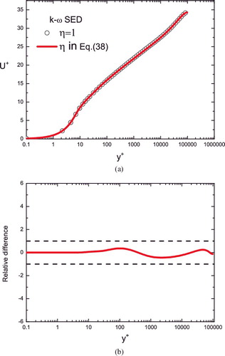
Before comparison with data, it is necessary to check that the modifications (Equation35(35) ) and (Equation38
(38) ) have negligible influence on the prediction of MVP – otherwise, we need to revise the previous modification. This is indeed verified, as shown in , where η in (Equation38
(38) ) changes the MVP by no more than 0.4%. This is tiny, compared to experimental uncertainty. Hence, (Equation31
(31) ), (Equation32
(32) ), (Equation33
(33) ) and (Equation35
(35) ) (with (Equation38
(38) )) are our final expressions for the modified k–ω equation, which results in accurate predictions of both MVP and SMKP, as demonstrated below.
Figure 11. (a) Predictions of five MVPs of the modified k−ω model (lines) compared with experimental TBL data. Reτ = 4000, 5100, 7000 are from Carlier and Stanislas [Citation41]; 13,600 from Hutchins et al. [Citation42], and 23,000 from Nickels et al. [Citation43]). Profiles are staggered vertically for a better display. (b) The relative errors, (UEXP/UModel − 1) × 100% of the modified k−ω model (with κ = 0.45 ) (solid symbols), are bounded within 2%.
![Figure 11. (a) Predictions of five MVPs of the modified k−ω model (lines) compared with experimental TBL data. Reτ = 4000, 5100, 7000 are from Carlier and Stanislas [Citation41]; 13,600 from Hutchins et al. [Citation42], and 23,000 from Nickels et al. [Citation43]). Profiles are staggered vertically for a better display. (b) The relative errors, (UEXP/UModel − 1) × 100% of the modified k−ω model (with κ = 0.45 ) (solid symbols), are bounded within 2%.](/cms/asset/3aac74e4-3b08-4322-bb93-bbed0765bd2f/tjot_a_1243244_f0011_c.jpg)
Figure 12. (a) Predicted mean velocities with and without anomalous dissipation modification in (Equation35(35) ). Note that η = 1 (symbols) means no modification while η in (Equation38
(38) ) (solid line) indicates the anomalous dissipation modification. (b) Relative differences (times 100) between the two mean velocity profiles in (a) are uniformly bounded within 0.4%, indicating that the η modification affects MVP very little.
4.3. Comparison of the new k–ω equation prediction with data
(a,b) shows the predictions of SMKP in pipes by the modified and the original k–ω equations, respectively. Data are from Hultmark et al. [Citation18] for five different Re's. The modified model reproduces the outer peak in sharp contrast to the original model predicting a constant plateau in the overlap region. The improvement is significant, entirely due to the introduced anomalous scaling factor (Equation38(38) ), with parameters given as below. The two scaling exponents are set to be constants: γb = 0.05 and γm = −0.09 (except for γm = −0.06 for the smallest Reτ =10,480), as mentioned above; the meso-layer thickness is fully specified as
with κ = 0.45. Finally, c ′ is a Re-dependent parameter, being set as 0.92, 0.97, 1.0, 1.0 and 1.0, respectively, for the five Re's varying from Reτ =10,480 to 98,187; thus, c ′ increases with increasing Re's and saturates to 1. Note that as shown in [Citation44], c ′ < 1 would underpredict the inner peak magnitude, because η → c ′ as y+ → 0. So, for the two moderate Re's, to compensate for the influence by c ′ < 1 for the inner peak, two parameters in the original k–ω model, i.e. Rk and Rβ (determining the transitions of α* and β*, respectively), are calibrated empirically. The original values, Rk = 6 and Rβ = 8, are now set to be Rk = 7 and Rβ = 11 for Reτ = 10, 480; and Rk = 6 and Rβ = 9 for Reτ = 20, 250, to take into account the moderate Re effect. The results are shown in (a), where the resulted inner peaks are invariant for all Re's, in satisfactory agreement with empirical data. In summary, with slight Re-dependence of Rk (going from 7 to 6) and Rβ (going from 11 to 9 and then to 8), we have obtained a consistently good description of SMKP in turbulent pipes through the factor η in (Equation38
(38) ) over a wide range of Re's.
Figure 13. Comparison between Princeton pipe data (symbols) [Citation18] and model predictions (lines). (a) Modified k–ω equation using (Equation38(38) ); (b) original k–ω equation with η = 1.
![Figure 13. Comparison between Princeton pipe data (symbols) [Citation18] and model predictions (lines). (a) Modified k–ω equation using (Equation38(38) ); (b) original k–ω equation with η = 1.](/cms/asset/acc49193-36a7-4934-8e0c-20d5815d7764/tjot_a_1243244_f0013_c.jpg)
We now apply the above description of the SMKP for TBL (channels are not discussed here for the lack of high Re data), in the hope of validating a unified k–ω model for all three canonical wall flows. Thanks to the recent measurements of SMKP by Vallikivi et al. [Citation20] of high Re TBL flows, one recognises a similar outer peak and a local logarithmic profile as in pipes; in contrast, the inner peak is slightly lower (by 0.5u2τ) than that in pipes. The experimental profiles are shown in for five different Reτ's varying from 4635 to 40,053 (over nearly one decade). We set j = 0 in (Equation31(31) )–(Equation33
(33) ) for flat geometry (κ, α∞, σ and γ are the same as in ). Comparison is made against η = 1 in (Equation35
(35) ), the original k–ω model, which, as shown in (b), yields a nearly constant plateau ⟨u′u′⟩ + ≈ 6.6 in the bulk flow region, significantly away from data. (a) shows the modified k–ω model with (Equation38
(38) ). The parameters are given as follows:first, γb = 0.05, y+B = 40 and Rk = 6 are the same for all Re's. For the two smallest Re's, i.e. Reτ = 4635 and 8261, γm = −0.03, −0.04; c ′ = 0.92, 0.94; and Rβ = 9, 8, respectively. For the remaining profiles, γm = −0.06, c ′ = 0.96 and Rβ = 7 are kept the same for all three larger Re's. The new predictions improve the original ones notably in the bulk flow region as well as in the inner peak region (y+ ≈ 10 ∼ 100), shown in (a).
Figure 14. Comparison between Princeton TBL data (symbols) [Citation20] and model predictions (lines). (a) Modified k–ω equation using (Equation38(38) ); (b) original k–ω equation with η = 1.
![Figure 14. Comparison between Princeton TBL data (symbols) [Citation20] and model predictions (lines). (a) Modified k–ω equation using (Equation38(38) ); (b) original k–ω equation with η = 1.](/cms/asset/f54d2acb-eadf-4d75-9379-7cf4cd3b69c5/tjot_a_1243244_f0014_c.jpg)
A notable point discussed here is the scaling of the inner peak of ⟨u′u′⟩ +. While it seems to be an invariant in the Princeton pipe [Citation18] and TBL [Citation20] data, however, Hutchins et al. [Citation42] (for TBL) and Lee and Moser [Citation46] (for channel) show that there is a trend toward a larger inner peak when Re increases. Thus, considering all recorded data, it is not certain that the inner peak keeps growing with increasing Re. Even if this was true, our modified k–ω equation still describes well the growth of the inner peak through the adjustment of the two parameters Rk and Rβ. These two parameters, which correspond to different values of α* and β*, influence the eddy viscosity and the dissipation in the near-wall region and thus affect the magnitude of the inner peak. Also note that the present version of the model does not apply to two-dimensional simulation of TBL, because (Equation31(31) )–(Equation33
(33) ) do not involve any streamwise variation along with inflow and outflow boundary conditions. The departure of predictions from data near the freestream in (a) reflects this; further treatment of this issue is beyond the scope of this paper.
4.4. Discussion for asymptotically large Re's
An important remaining issue is the asymptotic behaviour of SMKP for large Re's. It is a subtle issue compared to that of MVP which does not involve the dissipation anomaly. The question is how the anomaly varies as Re increases, since it is not certain whether current data have already reached the asymptotic similarity state such that the parameters in () become invariant for all Re's.
Let us first explain the asymptotic behaviour of SMKP when we keep γb, γm fixed (the meso-layer thickness y+M is fixed to be ). In this case, one obtains a power law scaling
and hence
for
. The resulting SKMP are shown in (a), where the solid lines are predictions for Reτ = 105, 106 and 107. While the inner peak keeps invariant, the outer peak exceeds the inner one at Reτ = 107. Moreover, the dashed line indicates the local power law scaling, agreeing well with the numerical result of the modified k–ω equation. The result indicates a possible power law scaling of SMKP for asymptotically large Re's, which is discernible from the logarithmic profile for Reτ over 107.
Figure 15. Comparison between data (symbols) and the predictions of the modified k–ω equation (solid lines). (a) The three parameters are invariant as Re, i.e. y+B = 40, γb = 0.05, γm = −0.09. Dashed line shows the local power law (y+)−0.18. (b) While y+B = 40 and γb = 0.05 are fixed, γm varies from −0.09 to −0.088, and to −0.085 for Reτ = 105, 106 and 107, respectively. Dashed line shows the log distribution with the slope −1.25.
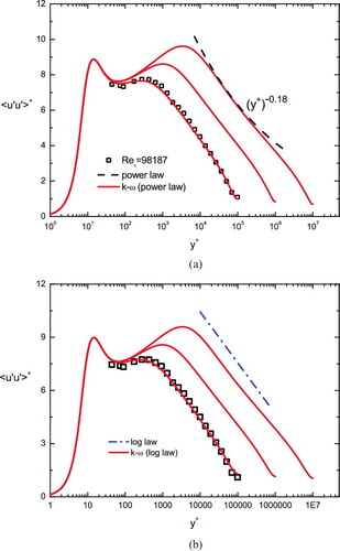
On the other hand, it is interesting to explore the possibility with the logarithmic scaling for SMKP in (Equation4(4) ). In fact, (Equation38
(38) ) also can result in a satisfactory approximation of the log profile through an Re-dependent scaling exponent, in analogy to the power law by Barenblatt [Citation47]. Note that from (Equation38
(38) ),
for
, and
. Thus, the logarithmic diagnostic function
. Since γb ≈ 0.05 is believed to be invariant, if γm∝Re− γbτ so that γmReγb − γmτ → const. and
as Reτ → ∞, then a constant Γ → const. is expected indicating the logarithmic scaling at asymptotically large Re's. In other words, to meet the log scaling as Reτ → ∞, we have γm∝Re− 0.05τ. It turns out that the convergence to such an asymptotic scaling is very slow, and here we verify that the magnitude of γm indeed decreases with increasing Re. In (b), we keep γb = 0.05 invariant and let γm = −0.09, −0.088, −0.085 for Reτ = 105, 106, 107, respectively. The predicted SMKPs are shown to exhibit more likely the log profiles marked by the dashed line, thus supporting current analysis.
Therefore, while the asymptotic scaling for SMKP is to be confirmed by more data, our modification factor (Equation38(38) ) reveals the capability to adapt to different asymptotic states of large Re.
5. Discussion and conclusion
We have presented a modified k–ω equation which predicts both MVP and SMKP with better accuracy than the Wilcox k–ω model for three canonical wall-bounded turbulent flows (channel, pipe and TBL), over a wide range of Re's. Three modifications are introduced: (1) an adjustment of the Karman constant for a better prediction of the overlap region, (2) an enhanced nonlinear turbulent transport (with parameter γ) corresponding to the wake structure, (3) and a dissipation factor η exhibiting an anomalous scaling for the meso-layer. The first two modifications yield a significant improvement of the MVP prediction (by nearly 10%), agreeing well with Princeton pipe data over a wide range of Re's, and the last one reproduces the outer peak of the SMKP for the first time.
Note that there are two main goals in this paper: to check the universality of κ, and to predict SMKP for the three canonical wall flows. It is not intended to give a mature CFD model applied in various flow systems in particular for those with complex boundary conditions (which is our future plan); still, the paper obtains several important results, discussed below. The most important result is that a single κ = 0.45 leads to highly accurate descriptions for more than 30 experimental MVPs covering all three canonical wall flows (channel, pipe and TBL). To emphasise, the universality of κ is a key issue not only for the fundamental study of wall turbulence (which is an outer standing question (Marusic et al. [Citation4])), but also for turbulent engineering applications (quoting Spalart's out claims ‘We have lost the Karman constant’ [Citation6]). To clarify this issue, highly accurate predictions of MVP are crucial to validate the values of κ, and the accuracy by the original k–ω model (with errors around 10%) is obviously not enough. The original k–ω equation is shown to fail in predicting correct overlap regions and wakes, and our modified version results in a good accuracy (in 98%–99% agreement). Although it may not be considered as the definitive proof of the universal Karman constant due to data uncertainty, we believe that κ, being part of the universal wall function, should itself be universal.
Second, the flow-dependent γ modification is motivated from physical considerations to characterise different known wake profile departures from the log-law, and it is important to discuss its generality. The nonlinear enhancement term in the eddy viscosity νT is a generic feature of the wake (increasing the wake profile above the log-law), supported by the above-mentioned fact that different choices of γ produces correctly the wake profiles for channel, pipe and zero-pressure gradient (ZPG) TBL. Note that a variation of γ from 20 to 40 only increases the wake profile by 3%, and it may be used to predict other more complicated wall flows with different wake profiles. Hence, it will be worthwhile to test how γ changes with pressure gradients [Citation48]. An example is the favourable-pressure gradient (FPG) TBL shown in . As we have explained, a smaller γ leads to a smaller weak strength; since the wake in FPG TBL is smaller than ZPG TBL, we would expect γ < 40 for the former. Also note that for TBL flows, κ varies with different pressure-gradient effects [Citation21,Citation49]. Thus, we adjust κ = 0.40 and γ = 30, and the predicted MVP agrees well with the experimental data by Oweis et al. [Citation49] at Reτ = 47, 000. Note that the inset of shows that the relative errors are within 2%. Such an agreement indicates that pressure-gradient effects can be well characterised by the parameter γ. Therefore, unlike the original k–ω model which fails to predict wake profiles, our flow-dependent γ gives an accurate description of the mean velocity in the wake region for all the flows – channel, pipe, ZPG TBL and FPG TBL.
Figure 16. Comparison of the MVP prediction by the modified k−ω model (solid line) for experimental TBL with favourable-pressure-gradient (FPG) effect (symbols) at Reτ = 47, 000 measured by Oweis et al. [Citation49]. Inset shows the relative error of our predictions bounded well within 2% (dashed lines).
![Figure 16. Comparison of the MVP prediction by the modified k−ω model (solid line) for experimental TBL with favourable-pressure-gradient (FPG) effect (symbols) at Reτ = 47, 000 measured by Oweis et al. [Citation49]. Inset shows the relative error of our predictions bounded well within 2% (dashed lines).](/cms/asset/aec8c61f-c7de-4dbc-95f9-9810f37b8580/tjot_a_1243244_f0016_c.jpg)
Third, for SMKP, three new parameters are involved, including the exponents γb and γm, and coefficient c ′; in reality, these parameters vary little. The coefficient c ′ is essentially one, varying from 0.92 to 1, and γb ≈ 0.05 is also held fixed for both pipe and TBL. The fact γb is constant is not surprising, since it characterises the meso-layer which is part of the overlap region, and hence part of the universal wall function. The only significant variation occurs in γm, from −0.09 to −0.06 for pipe and TBL, respectively, with slight Re-dependence; this is a typical feature of the bulk or wake property. Further study is needed to verify the universality of these parameter values. Also note that our current modification of dissipation introduced for the three canonical flows is a y+-dependent function. The viscous length scale y+ can be easily calculated when Reτ is given (for channel, pipe and TBL flows). However, for highly complex flows (e.g. wall curvature, flow separation), our simple approach needs to be extended. Thus, how to apply current model to predict more complex flows needs to be studied in future.
Therefore, significant improvement of the accuracy of CFD turbulence models can benefit from a careful study of the multi-layer structure of the mean flow. The present work shows that the wake modification and the anomalous dissipation factor for the meso-layer are good examples of physically inspired changes. Future work will investigate the connection between the multi-layer parameters and the k–ω model coefficients (i.e. β0, β*, σ, etc.) for wall functions, where the latter may eventually be replaced by the multi-layer parameters (amenable to adjustment for more complex flows).
Acknowledgment
We thank B. B. Wei who has contributed significantly during the initial stage of the work.
Disclosure statement
No potential conflict of interest was reported by the authors.
Additional information
Funding
References
- Smits AJ, Marusic I. Wall-bounded turbulence. Phys Today. 2013;66:25.
- Pope SB. Turbulent flows. Cambridge: Cambridge University Press; 2000.
- Davidson P. Turbulence: an introduction for scientists and engineers. Oxford: Oxford University Press; 2004.
- Marusic I, McKeon BJ, Monkewitz PA, et al. Wall-bounded turbulent flows at high Reynolds numbers: recent advances and key issues. Phys Fluids. 2010;22:065103.
- Smits AJ, McKeon BJ, Marusic I. High-Reynolds number wall turbulence. Annu Rev Fluid Mech. 2011;43:353–375.
- Spalart P. Turbulence. Are we getting smarter. In: Fluid Dynamics Award Lecture, 36th Fluid Dynamics Conference and Exhibit; San Francisco (CA); 2006. p. 5–8.
- Alfredsson PH, Imayamaa S, Lingwood RJ, et al. Turbulent boundary layers over flat plates and rotating disks - the legacy of von Karman: a stockholm perspective. Eur J Mech B-Fluids. 2013;40:17–29.
- Segalini A, Orlu R, Alfredsson PH. Uncertainty analysis of the von Karman constant. Exp Fluids. 2013;54:1460.
- Zagarola MV, Smits AJ. Mean-flow scaling of turbulent pipe flow. J Fluid Mech. 1998;373:33–79.
- McKeon BJ, Li J, Jiang W, et al. Further observations on the mean velocity distribution in fully developed pipe flow. J Fluid Mech. 2004;501:135–147.
- Marusic I, Monty JP, Hultmark M, et al. On the logarithmic region in wall turbulence. J Fluid Mech. 2013;716:R3.
- Nagib HM, Chauhan KA. Variations of von Karman coefficient in canonical flows. Phys Fluids. 2008;20:101518.
- Monkewitz PA, Chauhan KA, Nagib HM. Self-consistent high-Reynolds-number asymptotics for zero-pressure-gradient turbulent boundary layers. Phys Fluids. 2007;19:115101.
- Monkewitz PA, Chauhan KA, Nagib HM. Comparison of mean flow similarity laws in zero pressure gradient turbulent boundary layers. Phys Fluids. 2008;20:105102.
- She ZS, Wu Y, Chen X, et al. A multi-state description of roughness effects in turbulent pipe flow. New J Phys. 2012;14:093054.
- Wu Y, Chen X, She ZS, et al. On the Karman constant in turbulent channel flow. Phys Scripta. 2013;2013:014009.
- Wilcox DC. Turbulence modeling for CFD. Lake Arrowhead (CA): DCW Industries; 2006.
- Hultmark M, Vallikivi M, Bailey SCC, et al. Turbulent pipe flow at extreme Reynolds numbers. Phys Rev Lett. 2012;108:094501.
- Morrison JF, Mckeon BJ, Jiang W, et al. Scaling of the streamwise velocity component in turbulent pipe flow. J Fluid Mech. 2004;508:99–131.
- Vallikivi M, Hultmark M, Smits A. Turbulent boundary layer statistics at very high Reynolds number. J Fluid Mech. 2015;779:371–389.
- Nickels TB. Inner scaling for wall-bounded flows subject to large pressure gradients. J Fluid Mech. 2004;521:217–239.
- Del Alamo J, Jimenez J. Linear energy amplification in turbulent channels. J Fluid Mech. 2006;559:205–213.
- Panton RL. Composite asymptotic expansions and scaling wall turbulence. Phil Trans R Soc A. 2007;365:733–754.
- L’vov VS, Procaccia I, Rudenko O. Universal model of finite Reynolds number turbulent flow in channels and pipes. Phys Rev Lett. 2008;100:054504.
- Townsend AA. The structure of turbulent shear flow. 2nd ed. Cambridge: Cambridge University Press; 1976.
- Perry AE, Henbest S, Chong MS. A theoretical and experimental study of wall turbulence. J Fluid Mech. 1986;165:163–199.
- Marusic I, Kunkel GJ. Streamwise turbulent intensity formulation for flat plate boundary layers. Phys Fluids. 2003;15:2461.
- Smits AJ. High Reynolds number wall-bounded turbulence and a proposal for a new eddy-based model. In: Deville M, Le TH, Sagaut P, editors. Turbulence and interations. Berlin: Springer-Verlag; 2010. p. 51–62.
- Alfredsson PH, Segalini A, Orlu R. A new scaling for the streamwise turbulence intensity in wall-bounded turbulent flows and what it tells us about the outer peak. Phys Fluids. 2011;23:041702.
- Alfredsson PH, Orlu R, Segalini A. A new formulation for the streamwise turbulence intensity distribution in wall-bounded turbulent flows. Eur J Mech B-Fluids. 2012;36:167–175.
- Vassilicos JC, Laval JP, Foucaut JM, et al. The streamwise turbulence intensity in the intermediate layer of turbulent pipe flow. J Fluid Mech. 2015;774:324–341.
- Kolmogorov AN. The equation of turbulent motion in an incompressible viscous fluid. Izv Akad Nauk SSSR. 1942;VI:56–58.
- Saffman PG. A model for inhomogeneous turbulent flow. Proc R Soc Lond. 1970;A317:417–433.
- Saffman PG, Wilcox DC. Turbulence-model predictions for turbulent boundary layers. AIAA J. 1974;12:541–546.
- Wilcox DC. Reassessment of the scale determining equation for advanced turbulent models. AIAA J. 1988;26:1299–1310.
- She ZS, Chen X, Wu Y, et al. New perspective in statistical modeling of wall-bounded turbulence. Acta Mech Sinica. 2010;26:847–861.
- Coles D. The law of the wake in the turbulent boundary layer. J Fluid Mech. 1956;1:191–226.
- Wu XH, Moin P. A direct numerical simulation study on the mean velocity characteristics in turbulent pipe flow. J Fluid Mech. 2008;608:81–112.
- Ahn J, Lee J, Lee J, et al. Direct numerical simulation of a 30R long turbulent pipe flow at Re = 3008. Phy Fluids. 2015;27:065110.
- Monty JP, Hutchins N, Ng HCH, et al. A comparison of turbulent pipe, channel and boundary layer flows. J Fluid Mech. 2009;632:431–442.
- Carlier J, Stanislas M. Experimental study of eddy structures in a turbulent boundary layer using particle image velocimetry. J Fluid Mech. 2005;535:143–188.
- Hutchins N, Nickels TB, Marusic I, et al. Hot-wire spatial resolution issues in wall-bounded turbulence. J Fluid Mech. 2009;635:103–136.
- Nickels TB, Marusic I, Hafez S, et al. Some predictions of the attached eddy model for a high Reynolds number boundary layer. Phil Trans R Soc. A 2007;365:807–822.
- Chen X, Wei BB, Hussain F, et al. Anomalous dissipation and kinetic-energy distribution in pipes at very high Reynolds numbers. Phys Rev E. 2015;93:011102(R).
- Kadanoff LP. More is the same; phase transitions and mean field theories. J Stat Phys. 2009;137:777–797.
- Lee M, Moser R. Direct numerical simulation of turbulent channel flow up to Reτ ≈ 5200. J Fluid Mech. 2015;774:395–415.
- Barenblatt GI. Scaling laws for fully developed turbulent shear flows. Part 1. Basic hypotheses and analysis. J Fluid Mech. 1993;248:513–520.
- Slotnick J, Khodadoust A, Alonso J, et al. CFD vision 2030 study: a path to revolutionary computational aerosciences. Hampton (VA): NASA Langley Research Center; 2014. (Report no. NASA/CR 218178).
- Oweis G, Winkel E, Cutbrith J, et al. The mean velocity profile of a smooth-flat-plate turbulent boundary layer at high Reynolds number. J Fluid Mech. 2010;665:357–381.
Appendices
Appendix 1. Integrated mean momentum equation for pipe flows
For a fully developed steady pipe flow, the dimensional mean momentum equation (in cylindrical coordinates) reads
(A1) where
(δ the pipe radius). Integrating (EquationA1
(A1) ) with respect to
and using the constant pressure gradient condition (i.e. ∂xP = const.), we obtain
(A2) Defining the friction velocity as
, and assigning the positive v′ as the wall normal velocity pointing away from the wall, (EquationA2
(A2) ) is then
(A3) Normalising (EquationA3
(A3) ) with uτ and ν/uτ and defining Reτ = uτδ/ν, we obtain the integrated mean momentum equation (Equation6
(6) ) for pipes – the same as for channels.
Appendix 2. Dimensional modified k–ω equations
We rewrite the modified k–ω equations, i.e. Equations (Equation31(31) )–(Equation34
(34) ), into dimensional formulations, i.e.
(B1)
(B2) where j = 0 for channel and TBL and j = 1 for pipe; σ*SED/σ* = σSED/σ = 1 + γ2Re− 2τ(νT/ν)2. Note that the eddy viscosity νT = −⟨u′v′⟩/∂yU = α*kω is the same as the original k–ω equation. Also, (EquationB1
(B1) ) and (EquationB2
(B2) ) should be solved together with the integrated mean momentum equation (EquationA3
(A3) ).