
 ?Mathematical formulae have been encoded as MathML and are displayed in this HTML version using MathJax in order to improve their display. Uncheck the box to turn MathJax off. This feature requires Javascript. Click on a formula to zoom.
ABSTRACT
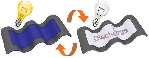
The emergence of soft energy devices provides new possibilities for various applications, it also creates significant challenges in the selection of structural design and material compatibility. Herein, we demonstrate a stretchable transmissive electrochromic energy storage device by inkjet-printing single layer of WO3 nanoparticles on an elastomeric transparent conductor. Such hybrid electrode is highly conductive and deformable, making it an excellent candidate for the application: large optical modulation of 40%, fast switching speed (<4.5 s), high coloration efficiency (75.5 cm2 C−1), good stability and high specific capacity (32.3 mAh g−1 and 44.8 mAh cm−3). The device consists of WO3-based hybrid electrode and polyaniline/carbon nanotubes composite electrode. It maintains excellent electrochromic and energy storage performance even when stretched up to 50%, and achieves a maximum areal energy density of 0.61 μWh cm−2 and power density of 0.83 mW cm−2, which is one of the highest values in stretchable transparent energy storage devices. A device featuring stretchable transparent nanowires based electrode is illustrated as an energy indicator in which the stored energy can be monitored via reversible color variation. This high performance and multifunctional electrochromic energy storage device is a promising candidate for deformable and wearable electronics.
Graphical Abstract
1. Introduction
The recent advances in wearable electronic devices with multi-functionality such as transparent, flexible, stretchability or printability have inspired the development of ‘smart and soft’ energy devices [Citation1–Citation5]. Electrochromic devices can reversibly change their colors at low power consumption and find applications in many areas, such as information displays, electronic paper, camouflage clothing, energy efficient smart windows and antiglare automotive mirrors [Citation6–Citation9]. Recently, more attention has been paid to flexible electrochromic devices because their application range can be extended to flexible displays, e-books, smart clothes and electronic camouflage skin [Citation10–Citation15]. Furthermore, electrochromic displays should be stretchable for future smart clothes and implantable display applications [Citation16], because the stretchability is a primary condition for wearable electronic systems [Citation17]. Stretchable electrochromic devices should be mechanically robust and deformable without performance degradation. They can conform to complex nonplanar surfaces, enabling integration into complex wearable systems [Citation18].
Integrating such electrochromic and energy storage effects is highly attractive to realize multifunctional portable electronic devices, because they are capable of indicating stored energy level and detection of these stored energy changes by visual color variation [Citation19–Citation22]. Several groups have fabricated electrochromic energy storage devices by deposition of various electrochromic materials such as vanadium oxide (V2O5) [Citation23], polyaniline (PANI)/WO3 [Citation24] and Prussian blue [Citation25] on transparent conducting oxide glass substrates. Recently, flexible electrochromic supercapacitors based on PANI nanowire (NW) arrays on polyethylene terephthalate (PET) substrates [Citation10] and cellulose-nanofiber/AgNW/reduced-graphene-oxide/WO3 composite electrode have been reported [Citation26]. However, there is a lack of reports in addressing the feasibility of stretchable electrochromic energy storage devices.
The electrochemical devices that possess both transparency and high stretchability still present an unprecedented challenge to date, because the electrode materials need to meet high transparency over a broad spectral range, high conductivity that does not degrade severely upon deformation, outstanding flexibility and compliance, and long-term atmospheric and electrochemical durability simultaneously. Silver nanowire (AgNW) percolation networks embedded in a polymer matrix have been widely studied as one of the most competitive ST electrodes [Citation27] for the wearable electronic systems such as sensors [Citation28], heaters [Citation29], electromagnetic interference shielding films [Citation30], etc. However, it is still a great challenge to develop stretchable transparent (ST) electrodes with highly conductivity and stability for electrochemical devices, because of the trade-off between required transparency and conductivity/stretchability/durability. For stretchable transparent electrochromic devices (STEDs), Bao and coworkers reported a stretchable e-skin by coating electrochromic polymers on single-wall carbon nanotubes (SWCNTs) elastic conductors [Citation18]. The device maintained its electrochromic properties at 20% strain state, but the electrochromic properties degraded quickly at 50% strain state. Our group also demonstrated the stretchable electrochromic devices which can maintain their electrochromic properties up to 50% strain states using AgNW/polydimethylsiloxane (PDMS) [Citation16], which is a reflective electrochromic type. Similarly, Liu and coworkers reported an elastomeric electrochromic device using AgNW/PDMS electrodes [Citation31], but the device could not be stretched. For stretchable transparent energy storage devices (STESDs), pre-strained CNT or graphene electrodes have been used [Citation32–Citation34], but the device had a low areal energy density as the nanocarbon films need to be thin enough to secure the transparency. Recently, the areal energy density of STESDs has been increased more than tenfold by adopting metal nanowires networks, e.g. Au NWs [Citation35], core-shell nanowires structures, e.g. Ag-Au [Citation36], Ag-Au-polypyrrole [Citation37] and Ag-Ni [Citation38]. However, these values are still around a tenth of those in the flexible transparent energy storage devices, e.g. graphene-FeOOH//graphene-Co(OH)2 [Citation39], because metal NWs or core-shell networks only cover a small portion of the entire electrode to maintain the transparency. In addition, metal-based ST electrodes still suffer from oxidation and corrosion in both air and electrolytes, impeding the practical electrochemical applications. For these reasons, one prior work attempted the stretchability of hybrid electrochromic-supercapacitor device using PANI/pre-strained carbon-nanotubes (CNTs) [Citation40], but the electrochromic performance of the device was not investigated under stretched mode. Therefore, innovative design of stretchable transparent electrode and device configuration are urgently required to realize high-performance stretchable transmissive electrochromic energy storage devices (STEESDs).
Herein, we proposed a novel strategy to fabricate AgNWs-based ST electrode for high-performance and stable STEESDs: (1) WO3 was selected as the electrochromic material because the operating potential of WO3 could reach below 0 V vs Ag/Ag+ (−0.6 V to −0.2 V), which was beneficial to the electrochemical stability of AgNWs-based ST electrode by retarding the electrochemical oxidation of AgNWs; (2) a thin poly(3,4-ethylenedioxythiophene)-poly(styrene sulfonate) (PEDOT:PSS) film as buffer and passivation layer was deposited between WO3 and AgNWs/PDMS because PEDOT:PSS could prevent the oxidation of Ag [Citation41], as well as provide better conductive pathway between WO3 nanoparticles and AgNWs; (3) transmissive WO3 nanoparticles were inkjet-printed uniformly on the PEDOT:PSS/AgNWs/PDMS. As a precise and non-contact direct write technique, inkjet-printing allows high resolution patterns with efficient use of materials, as well as low-cost and scalable production of high-quality homogeneous film on all kinds of substrates, which can provide multifunctionalities and improved performance [Citation42,Citation43]. Moreover, the inkjet-printing method allows precise thickness control as well as flexible patterns design compare to traditional coating process of WO3 such as spray coating, spin coating and dip coating [Citation44,Citation45]. Inkjet-printing has been extensively utilized for printing functional materials including metal nanoparticles [Citation46,Citation47] and metal oxide nanoparticles [Citation48,Citation49] on various substrates for flexible electronics. Despite some prior works on inkjet-printed metal oxide films on hard (conductive glass) [Citation50] or flexible (PET, polyimide) substrates [Citation51,Citation52], inkjet-printed metal oxide film on elastomer substrate has been particularly daunting, because the surface tension and wettability of the ink is not compatible with the elastomer substrate. In this study, a thin and uniform WO3 layer was successfully inkjet-printed on the elastomer by virtue of PEDOT:PSS buffer layer that could enhance the compatibility between ink and elastomer substrate. As a result, the inkjet-printed WO3 electrode can provide higher areal capacity in comparison to the conventional core-shell structures [Citation36–Citation38] or electrodeposited WO3 on AgNWs [Citation16], where active materials were just localized around AgNWs network. Furthermore, it can maintain its electrochromic and energy storage functionalities when stretched up to 50%. Based on these findings, the hybrid energy storage device was demonstrated for STEESDs, in which the change of the stored energy level can be monitored by coloration (or transmittance modulation). Such hybrid electrode and device have achieved the highest performance among other ST electrodes based on their electrochromic and energy storage properties.
2. Experimental details
2.1. Electrode preparation
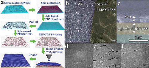
The ST conductors were fabricated through a modified approach on previously reported methods as shown in ) [Citation53,Citation54]. AgNWs solution was diluted to 0.3 mg mL−1 before use. The glass slides were washed with acetone, then de-ionized water, and finally isopropanol in an ultrasonic bath for 15 min, respectively, and then blow-dried with argon gas. The diluted AgNWs solution was uniformly spray-coated onto the pre-cleaned glass slides by a spray gun inside the fume hood. The solvent was evaporated immediately by heating on a hot plate at 100 °C. Thereafter, SiO2 nanoparticles suspension were prepared by dispersing SiO2 nanoparticles in ethanol (concentration of 3.5 wt %) and then, the suspension was spin-coated onto the AgNWs/glass surface at 1000 rpm for 50 s. PDMS was prepared by mixing the base and the cross-linking curing agent in a ratio of 10:1. The liquid mixture was poured onto the transparent conductive substrate, and then cured at 60 °C for 2 h. After that, the films were dipped into deionized water at 50 °C for 30 min. The ST conductors were obtained by peeling the composite film from the glass slides. The stable ST conductors were fabricated by spin-coating one layer PEDOT:PSS onto the ST AgNWs/PDMS substrates. Finally, the ST conductors were heated at 135 °C for 30 min for PEDOT:PSS curing. The WO3 nanoparticles and ink were prepared according to our previous report [Citation55]. The WO3 films were printed on stable ST PEDOT:PSS/AgNWs electrode, and dried at 60 °C for 2 h.
Figure 1. (a) Schematic illustration of fabrication procedure of the inkjet-printed stretchable WO3 transparent electrode. (b) SEM images of the inkjet-printed stretchable WO3 transparent electrode, showing parts of printed WO3 track. (c) The cross-section SEM images of printed WO3 PEDOT:PSS/AgNWs/PDMS electrode with about 400 nm thick WO3 layer and 530 nm thick PEDOT:PSS/AgNWs. (d-f) SEM images of the WO3 printed ST electrode at (d) 0% strain, (e) 50% strain, (f) after releasing the sample from 50% strain to the relaxed state.
2.2. Device fabrication
A stretchable electrode based on a mixture of PANI and multi-wall carbon nanotubes (MWCNTs) was synthesized by a previously reported water-surface-assisted route with modifications [Citation56]. In a typical synthesis of the PANI/MWCNT, 4 g of PDMS and 0.4 g of MWCNT were dissolved and sonicated in 50 mL of xylene, and then poured onto the DI water in a petri-dish. After the PDMS was completely cured and the xylol had volatilized, 50 nm-thick gold layer was deposited onto the MWCNTs conductor to enhance the conductivity, and then PANI polymer was electrodeposited onto the resultant stretchable MWCNTs conductor in a solution of 0.1 M aniline and 1 M H2SO4. Stretchable electrochromic energy storage devices have been assembled with WO3/PEDOT:PSS/AgNWs/PDMS, PANI/MWCNT, H2SO4/PVA gel and 3M VHB tape as the negative electrode, positive electrode, electrolyte and separator, respectively. The capacity of two electrodes in energy storage device has been charge balanced by adjusting the area ratio of each electrode.
2.3. Characterization
The structure, composition and morphology of the stretchable samples were characterized by field emission scanning electron microscopy (FESEM, JEOL 7600F, Tokyo, Japan) and Energy Dispersive X-ray spectroscopy (EDS) mapping. A customized stretching stage was used to test the change in the resistance upon stretching. Keithley analyzer (Model 4200, Cleveland, OH, USA) was used to measure the relative resistance changes under different strains. Sheet resistance of the ST electrodes was measured by a four-point probe (Jandel RM3000, Linslade, UK), taking into the account that each reported data is based on the mean of 5 measurement points. The luminance of one LED was tested under different tensile strains from 0% to 100% by a Konica CS-200 (Osaka, Japan) spectroradiometer. Electrochromic performance and galvanostatic charging/discharging curves were measured in the three electrode system with spring coiled Pt wire and Ag wire as the counter and reference electrodes in gel electrolyte composed of 0.5 M H2SO4 and 10wt % PVA. The transmittance of sample was detected by SHIMADZU UV-3600 spectrophotometer (Tokyo, Japan). Solartron 1470E was used to measure CV, galvanostatic charging/discharging curves and EIS curves. For the electrochromic energy storage tests, the tests were performed in the two-electrode system, in which the PANI/MWCNT electrode with a window frame design was assembled as the working electrode and the stretchable WO3/PEDOT:PSS/AgNWs film was used as the counter electrode, respectively.
3. Results and discussion
3.1. Microstructure change under strain
) illustrates the fabrication procedure of a stable ST electrode for STEESDs. The diluted AgNWs solution was uniformly spray-coated onto the pre-cleaned glass slides by a spray gun inside the fume hood. Thereafter, SiO2 nanoparticles suspension was spin-coated on the AgNWs/glass surface. The SiO2 nanoparticles can tremendously improve the transfer efficiency of AgNWs via strong van der Waals interaction with PDMS polymer matrices and AgNWs [Citation57]. The ST electrode without SiO2 nanoparticles was also prepared, the sheet resistance is more than 680 times higher than that of the ST electrode with SiO2 nanoparticles. Therefore, the ST electrode without SiO2 nanoparticles could not meet the requirements of the electrochromic device due to its high sheet resistance. The liquid PDMS mixture was poured onto the transparent conductive AgNWs/glass substrate, and then cured. The ST conductors were obtained by peeling the composite film from the glass slides. After that, one layer of PEDOT:PSS was spin-coated onto the ST AgNWs/PDMS conductors, and then the ST conductors were heated for PEDOT:PSS curing. As shown in the SEM images of the AgNWs electrode before and after coating PEDOT:PSS (Figure S1a and b), part of the AgNWs are embedded in the elastomer matrix while part of them are protruding, in which the exposed protrusions can serve as the conducting sites. The enlarged image of the AgNW (the inset of Figure S1a) shows that the SiO2 nanoparticles are wrapped tightly around the AgNW. There is no obvious difference in the morphology after coating PEDOT:PSS on the AgNWs/PDMS except that an additional thin layer of polymer can be observed on the surface. The homogeneous distribution of PEDOT:PSS on the whole surface of AgNWs/PDMS was further verified by EDS mapping by tracing the sulfur element that is present in the PEDOT:PSS (Figure S1c). Finally, electrochromic active WO3 nanoparticles were deposited onto the PEDOT:PSS/AgNWs via inkjet-printing approach. PEDOT:PSS as a buffer layer promotes the uniform distribution of WO3 nanoparticles with controlled thickness of about 400 nm on the conducting elastomer surface (). The microstructural change in the prepared electrode was observed by SEM under 0% strain, 50% strain, and the relaxed state (recovered from 50% strain) as shown in ). The crack widths were about 250 − 500 nm at 0% strain ()), and increased to more than 1 μm at the 50% strain ()), and most of the wide cracks become narrower after the electrode recovered from 50% strain to the relaxed state ()). These results imply that the prepared electrode can retain its electrochemical functionality under high mechanical deformation, which is highly desirable for the STEESDs.
3.2. Optical and electrical properties under strain
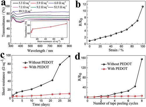
The prepared ST electrodes offer the advantage of corrosion resistance, strong adhesion and excellent mechanical durability. The PEDOT:PSS/AgNWs electrodes display flat transmittance spectra with excellent transmittance in the wavelength range of 300−900 nm ()). The transmittances at 550 nm for the 9.2 Ω sq−1, 52.5 Ω sq−1 and 89.3 Ω sq−1 electrodes are 71%, 77% and 84%, respectively (the inset of )), which are comparable to the flexible Cu [Citation58] and Ag [Citation59] based transparent electrodes, and superior to graphene [Citation60], carbon nanotube [Citation61] and conducting polymer [Citation62] based transparent electrodes. The normalized resistance variation (R/R0) upon stretching indicates that the R/R0 linearly increased to 4.4 until 70% strain, and gradually reached 11.3 at 100% strain ()). This stretchability is superior to other AgNWs-based conductors such as AgNWs embedded in PDMS with Zonyl FS-300 fluorosurfactant [Citation53] and AgNWs embedded in polyurethane acrylate (PUA) [Citation63]. The figures of merit of our ST electrodes was demonstrated by lighting up some LED indicators at various tensile strains (Figure S2); the LED maintains its brightness up to 70% strain and still displays significant brightness at 100% strain. For metal-based transparent conductors, maintaining long-term stability in air is of dire concern as it may impede practical applications. The degradation mechanism is largely due to the oxidizing or corrosion effects in air [Citation64–Citation66]. In order to illustrate the passivation role of PEDOT:PSS to prevent the oxidation of Ag in air, the ST electrodes without (9.3 Ω sq−1) and with PEDOT:PSS (6.0 Ω sq−1) was exposing in air under 25 °C and 65% RH for 30 days. The sheet resistance of the ST electrode with PEDOT:PSS layer is reduced because the junctions between the silver nanowires are tightly bridged by the conductive PEDOT:PSS polymer. The ST electrode with a PEDOT:PSS layer exhibits excellent stability than that of the ST electrode without PEDOT:PSS layer ()). The result proves that the PEDOT:PSS passivation layer can improve the corrosion resistance of the silver-based transparent conductors. Remarkably, the PEDOT:PSS passivation layer also enhances the adhesion between AgNWs and the PDMS substrate. As shown in ), the electrode with PEDOT:PSS layer is able to withstand more cycles of repeated tape peeling test compared to electrodes without PEDOT:PSS layer. The enhanced mechanical stability of Ag nanowire network is attributed to the nanojoining of PEDOT:PSS at the metal nanowire junctions [Citation67].
Figure 2. (a) Transmittance spectra of ST conductors with different AgNW densities that show different conductivities. Inset shows the sheet resistance vs optical transmission (at 550 nm) for the ST conductors. (b) Normalized resistance (the ratio of the instantaneous resistance under different strains to the initial resistance before stretching) of the ST conductor as a function of tensile strain. (c) Variations in sheet resistance of the ST conductor with and without PEDOT:PSS exposed in air at ambient temperature for 30 days. (d) Changes in sheet resistance of the ST conductor with and without PEDOT:PSS as a function of the number of cycles of repeated peeling tests by 3M Scotch tape. The same batch electrodes were used in Figure 2(b–d), the initial sheet resistance of the ST conductor without PEDOT:PSS is 9.3 Ω sq−1, it changes to 6.0 Ω sq−1 after coating PEDOT:PSS.
3.3. Electrochemical properties under strain
3.3.1. Electrochromic performance
The typical redox peak of WO3 material was observed in the CV curves of the WO3/PEDOT:PSS/AgNWs electrodes under different scan rates (10–100 mV s−1) in the potential range of −0.7 to 0.05 V (Figure S3), which is attributed to the H+ insertion/extraction according to the following reversible reaction:
A dark blue color was observed when a negative potential was applied to the film due to the insertion of H+ ions into the film, leading to the reduction of the W6+ ions to a lower valence state. The dark blue color of HxWO3 film faded away when a positive potential was applied due to the extraction of H+ ions from the WO3 film, in which the reduced W-ions were oxidized back to the higher valence states. As the scan rate increased, larger redox polarizations were observed where the oxidation peaks moved to more positive direction and reduction peaks shifted to more negative direction because of the internal resistance of electrodes. The thickness of PEDOT:PSS/AgNW/PDMS conductor is very important, because it affects both transparency and conductivity ()), as well as electrochemical properties of the electrode. The CV curves with various thickness of PEDOT:PSS/AgNW/PDMS conductors were also measured to determine the relationship between the electrochemical properties and thickness of PEDOT:PSS/AgNW/PDMS conductors (Figure S4). For thinner electrode (530 nm), higher transparency was obtained but the electrode showed poor electrochemical property. The thicker electrode (1200 nm) showed higher electrochemical property, but exhibited low transparency. Therefore, the optimum thickness of the electrode was determined around 680 nm.
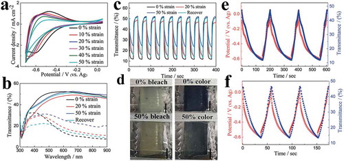
) shows the CV curves of the electrodes with varying uniaxial strain up to 50%. During the stretching process, the normalized area of the CVs curves remained 87.2% at 40% strain and 73% even at 50% strain (Figure S5), illustrating the remarkable stability under deformation. The transmittance spectra of the sample in both colored and bleached states were measured over a wavelength region from 300 to 900 nm ()), respectively. The sample displays an optical modulation, ΔT% (ΔT% = Tb%−Tc%, where Tc and Tb is the transmittance of the colored and bleached electrochromic film at a certain wavelength, respectively) of about 40% at 633 nm under 0% strain state. The optical modulation decreased slightly with increasing strain, because the transmittance in cathodic colored state was slightly increased (less intense color) with increasing strain but the transmittance in the anodic bleached state remained similar. However, it still maintained 69.8% of its initial optical modulation at 50% strain (Table S1). Moreover, the optical modulation can be recovered to 90% of its initial value after releasing the sample from 50% strain to its relaxed state (0% strain), indicating our sample has an excellent deformability without largely sacrificing its electrochromic properties. Under a square-wave potential between −0.7 and 0.05 V (Figure S6), the corresponding current density (Figure S7) and in situ kinetic transmittance curves at different strain states were obtained, respectively (). The current density decreased with increasing strain, which is consistent with the CV curves. The switching time was calculated from the in situ kinetic transmittance curves as 90% of the optical modulation between the fully bleached and colored states. At 0% strain, the switching time for coloration and bleached process was 4.1 and 2.1 s, respectively. The switching time was slightly increased upon stretching, but all the switching processes were completed within several seconds to tens of seconds. Moreover, the electrochromic films still exhibited electrochromic performance even under highly stretched states at 70% and 80% as shown in Figure S8. ) and Figure S9 show the electrochromic films at bleached and colored states under different strain (0%−50%) states, indicating that our electrochromic films maintained their electrochromic properties even at highly stretched conditions.
Figure 3. (a) CV curves of the printed ST WO3 electrodes with different tensile strains at a scan rate of 20 mV s−1. (b) Transmittance spectra of WO3 coated ST electrodes with different tensile strains in the colored and bleached states. (c) In situ transmittance response of WO3 coated ST electrodes with different tensile strains measured at 633 nm. (d) Photographs of the WO3 coated ST electrodes in the bleached and colored states at 0 and 50% strain, respectively (scale bar: 5 mm). Galvanostatic charge/discharge curves at current density of (e) 0.3 mA cm−2 and (f) 0.6 mA cm−2 in the potential range of 0.05 to −0.6 V and corresponding in situ transmittance responses collected at 633 nm for the WO3 coated ST electrodes.
Coloration efficiency (CE) is one of the most important parameters that relates the efficiency with the optical density (ΔOD) and the unit charge insertion (ΔQ), as follows:
Higher CE indicates that the electrochromic materials can achieve larger optical modulation with less energy. Figure S10 shows the relationship between ΔOD and ΔQ at a wavelength of 633 nm during a typical coloration at −0.7 V under different strain states. From the linear region of the ΔOD-ΔQ curves, CE was calculated to be 75.5 cm2 C−1 at 0% strain state (Table S1). Up-to-date, the CE of 75.5 cm2 C−1 is the highest value among the stretchable electrochromic films and devices [Citation16,Citation31]. Although the CE decreases under stretched states, the value still reached 36.2 cm2 C−1 and can be recovered to 57.1 cm2 C−1 after releasing the sample from 50% strain to its relaxed state (0% strain). The underlying stretchable mechanism can be illustrated by the unique microstructural change in the WO3 printed ST electrode as shown in ); most of the wide cracks that are induced during stretching become narrower after releasing the electrode to the relaxed state. Indeed, some irreversible microcracks can also be formed on the film after the first cycle of stretching and releasing, which would affect the electrochemical performance slightly.
The EIS of the WO3 coated stretchable transparent electrode under different strain states were further measured in the frequency range of 100 kHz to 0.01 Hz to understand the electrochemical behaviors as shown in Figure S11. All Nyquist plots of the electrode under different strain states exhibited a semicircle in the high-frequency and a straight line in the low-frequency region. The semicircle represents the charge-transfer resistance during the electrochemical reaction. The straight line in the low-frequency region can be ascribed to the diffusion-controlled Warburg impedance. Apparently, in the stretched state, there is minimal change in the Nyquist plot of the ST electrode. The semicircle becomes slightly larger (from 10 Ω to 30 Ω) while the slope of the straight line experienced slight decrease with the increased strain states up to 50%, indicating that the higher strain state has led to higher charge-transfer resistance and lower ion diffusion.
3.3.2. Energy storage performance
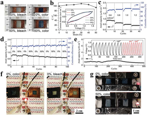
In order to illustrate the feasibility of the ST electrode as an electrochromic energy storage electrode, charge/discharge curves and in situ kinetic transmittance curves at 633 nm were measured at different current densities (). The charge/discharge curves exhibit approximate symmetrical triangle shape, indicating good reversibility. When charging, the ST electrode experienced a color change from transparent to dark blue. During the discharging process, the color of the ST electrode faded away and the electrode recovered its transparent state when the charged energy has been consumed. Hence, the level of the stored energy in the electrochromic energy storage device can be predicted by the noticeable color change. The areal capacity was calculated according to the equation of C = IΔt/A/3600, where C (mAh cm−2) represents the areal capacity, I (mA) denotes the discharge current, and Δt (sec) and A (cm2) is the total discharge time and the area of the film, respectively. The areal capacity of the WO3 coated ST electrodes reached 4.84 μAh cm−2 (32.3 mAh g−1 at 2 A g−1 based on the weight of dried WO3 ink, 44.8 mAh cm−3 at 2.78 A cm−3 calculated based on the total volume of WO3/AgNWs-PEDOT) and 3.88 μAh cm−2 (25.8 mAh g−1 at 4 A g−1, 35.9 mAh cm−3 at 5.56 A cm−3) at current density of 0.3 and 0.6 mA cm−2, respectively. Such areal capacities are much higher than those previously reported pure WO3 materials [Citation68–Citation70] and our recently reported WO3/PEDOT:PSS composites [Citation50], and is also comparable to the WO3/PANI composites [Citation68] and other transparent capacitor films such as graphene wrapped Ni(OH)2 nanosheet film [Citation71] or graphene-hollow-cubes film [Citation72].
3.3.3. Electrochemical and mechanical stability
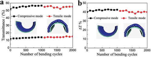
To evaluate the electrochemical and mechanical stability, the long-term kinetic transmittance curves at 633 nm were measured at initial 0% strain (Figure S12) and relaxed state after the electrode recovered from 50% strain (Figure S13). The unstretched sample retained a transmittance modulation of 69.5% of its initial optical modulation after 20,000 s continuous coloration–bleaching testing (500 switching cycles, Figure S12). The sample that was initially stretched to 50% strain then recovered to relaxed state still sustain a transmittance modulation of 70.1% of its original value after 10,000 s continuous coloration–bleaching testing (250 switching cycles, Figure S13). Additionally, the sample retained a transmittance modulation of 72.3% of its original value after 500 stretch/recover cycles between 0% and 50% strain (Figure S14). Moreover, the sample could withstand the compressive and tensile bending tests for 1000 cycles, respectively (with a curvature radius of 5 mm), and without compromising the transmittance modulation (). The resistance of the ST electrode was gradually reduced during compressive bending mode, finally reached a relatively stable value. The resistance was slightly increased during the first 100 tensile bending tests, and then attained a relatively stable value. All in all, there is no big resistance fluctuation under long term bending cycling test (Figure S15). These results indicate that the ST electrodes exhibit remarkable electrochemical and mechanical stability.
Figure 4. The mechanical stability of the WO3 coated ST electrode in the bleached and colored state under repeated compressive and tensile bending tests with a curvature radius of 5 mm. (a) The transmittance of the WO3 coated ST electrode at 633 nm in the bleached and colored state as a function of number of bending cycles. (b) The optical modulation of the WO3 coated ST electrode at 633 nm as a function of number of bending cycles.
3.4. Applications
3.4.1. Inkjet-printing and wearable devices
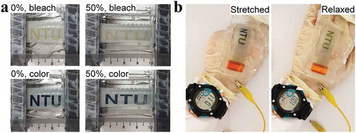
One of the appealing merits of the inkjet-printed STEESDs is the aesthetic versatility. To prove the concept of STEESDs for wearable electronics application, the letter (‘NTU’)-shaped WO3 was inkjet-printed on the ST conductors. The letter-printed electrode showed distinct pattern switching between colored and bleached state under 0% and 50% tensile strains ()). Moreover, such color change can still be observed clearly during stretching/releasing process, demonstrating the almost non-destructive printed electrode under repetitive stretching test. ) illustrates the mounting of letter-printed WO3 electrode (working electrode) on the glove and connected to a coiled Pt wire that serves as the stretchable counter electrode. The charged single cell of the letter-printed electrode was used to power the digital watch and continued to function during repeated hand gripping and releasing. A single charge of the letter-printed electrode could power the watch for more than 2 min 20 sec (Movie S1). It is noteworthy that the letter-printed electrode was charged with its color changing from transparent to dark blue, and was accompanied by the blue color fading during power delivery, demonstrating both the electrochromic indicator and power delivery functions. It demonstrates that the inkjet-printed STEESD is useful as a monolithically and aesthetically mountable power source in diverse future soft electronic systems, e.g. wearable sensors, transparent displays, human-machine interfaces, and IoT.
Figure 5. (a) Photographs of the inkjet-printed, letter (‘NTU’)-shaped WO3 on ST conductors in discharged (bleached) and charged (colored) states under 0% and 50% tensile strains. (b) Photographs show the operation of the watch by a single cell of the inkjet-printed, letter (‘NTU’)-shaped WO3 electrode (negative electrode) that was mounted on the glove and connected to a Pt wire as the counter electrode, demonstrating the electrochromic and power delivery functions under both stretched and relaxed states.
3.4.2. Device performance under strain
For the versatile applications such as integration into a smart window or deformable display, two-electrode system and all solid state STEESD was further demonstrated using a hybrid-type energy storage device. To ensure the stability of AgNWs-based ST electrode in the negative potential range, the stretchable PANI/MWCNT/PDMS composite was selected as the positive electrode material because it has a higher capacitive potential range (0–0.8 V vs Ag/AgCl) than that of WO3. By placing the stretchable PANI/MWCNT/PDMS electrode at the lateral sides of the device, the STEESD was successfully assembled. Because the prepared PANI/MWCNT electrodes covered only the lateral sides of the device, most area of the as-prepared device is transparent as shown in ). The PANI polymer was uniformly deposited onto the MWCNT/PDMS composites and exhibited a typical faradaic behavior between 0 and 0.8 V vs Ag/AgCl (Figure S16). The electrochromic performance of the device is almost not affected in this two-electrode device configuration (Figure S17), except for a reduced switching speed (22.4 s and 34.2 s for coloration and bleached processes, respectively). In addition, reversible color changes were clearly observed up to 50% strain during the charging/discharging ()). Movie S2 illustrated the charge-discharge cycles of the device under various tensile strain from 0 to 50%. The device showed deep blue coloration during the charged state and became transparent during the discharged state even at 50% strain, demonstrating the good stretchability of STEESD. Relative capacity change also indicates the good stretchability of the device – the original capacity could be maintained at 94% until 50% strain ()) and no substantial change was observed in the CV curves when stretched up to 50% strain (the inset of )). Such CV response of the assembled device exhibited a broad redox peak at 0–1.5 V, signifying that the capacities of the negative (WO3) and positive (PANI/MWCNT) electrodes were well-modulated to balance the charges. The device delivered reversible discharge capacity of 0.83 μAh cm−2 at 0.6 mA cm−2, 0.63 μAh cm−2 at 0.8 mA cm−2, 0.5 μAh cm−2 at 1.0 mA cm−2 and 0.42 mF cm−2 at 1.2 mA cm−2 ()), which surpassed the values reported on stretchable transparent energy storage devices (Table S2) [Citation32,Citation33,Citation35,Citation37,Citation38,Citation73]. ) shows the capacity retention of the device measured from galvanostatic charge-discharge profiles under relaxed (0%) and stretched (50%) states alternatively in every 10 cycles, indicating that the device retained its capacity even under the repeated stretching/releasing. The average equivalent internal resistance (ESR) values were estimated to be ~ 2.4 kΩ from the IR drop in discharge curves (Figure S18a) in both 0% and 50% tensile states, indicating that ESR values were almost unchanged during deformation. It is consistent with the EIS analysis of WO3 electrode, where the series resistance of WO3 electrode maintained similar (~ 15 Ω) during all range of tensile states (Figure S11). Furthermore, the capacity of the device maintained approximately 85% of its initial value after 400 charge–discharge cycles () and S18b), demonstrating good cycling stability as an energy storage unit. The capacity slowly decreased to 69% after 500 cycles. Additionally, the capacity of the device only shows a minute fluctuation during the 500 cycles bending tests (Figure S19). In addition, the device can deliver a maximum areal energy density of 0.61 μWh cm−2 and still maintain 0.3 μWh cm−2 at a high power density of 0.83 mW cm−2 (Figure S20), which is much higher than those stretchable energy storage devices with 50% transmittance [Citation38,Citation73,Citation74]. As a proof of concept, two devices were charged (color changing from transparent to dark blue) could successfully light up an LED and were accompanied by the blue color fading during power delivery (), Movie S3), demonstrating practical application as an indicator of the energy storage state. Furthermore, as shown in ) and Movie S4, two devices that were connected in series could power the LED even at 50% strain. These color changes could be clearly observed during the entire charge-discharge cycles. The prototype device has demonstrated that it can maintain its electrochromic and energy storage performance, as well as powering the LED light even when subjected to tensile strain. Such multi-functional and high-performance electrochromic energy storage device could be a versatile power source for next-generation soft electronics.
Figure 6. (a) Photographs of the electrochromic energy storage device composed of WO3/PEDOT:PSS/AgNWs and PANI/MWCNT electrodes as the anode and cathode, respectively. The device was discharged (bleached) and charged (colored) under 0% and 50% tensile strains. (b) Change of the capacity of the device with increasing strains. The inset shows CV curves at a scan rate of 20 mV s−1 with various strains (0 – 50%). (c) Areal capacity versus cycle number of the device cycled 10 times at different current densities (0.6, 0.8, 1, and 1.2 mA cm−2) and its corresponding Coulombic efficiency. (d) Areal capacity versus cycle number of the device under relaxed (0%) and stretched (50%) states at every 10 cycles. (e) The long-term cycling performance during 500 cycles. The inset shows the corresponding galvanostatic charge–discharge profiles in the voltage range from 0 to 1.5 V. (f) PANI/MWCNT(+)//WO3/PEDOT: PSS/AgNWs(−) electrochromic energy storage devices connected in series lit up a commercial LED, demonstrating the energy storage performance and optical color change during power delivery and upon completion of discharging. (g) Two devices connected in series turned on a LED light under relaxed (0%) and stretched (50%) states.
4. Conclusions
In summary, multifunctional STEESDs were validated using highly stretchable transmissive metal-based composite electrodes, where the stored energy can be monitored by reversible color variation. The hybrid electrodes exhibit remarkable mechanical properties, high conductivity and high stability against oxidation. It is noteworthy that inkjet-printing technology was used to prepare the thin WO3 layer on the transparent conducting elastomer. We found that PEDOT:PSS as a buffer layer promoted the uniform distribution of WO3 nanoparticles with a controlled thickness of a few hundred nanometers on the elastomer surface, so that the electrode retained its transparency and stretchability after the printing of metal oxide nanoparticles. As a result, the electrode can maintain its electrochromic and energy storage functionalities even when stretched up to 50%, because the WO3 film cracks uniformly without incurring any debonding. Even if highly stretched (80% strain), the electrode still demonstrated electrochromic performance. Moreover, as a proof of concept, a hybrid energy storage device was demonstrated as STEESDs with novel features. Such hybrid electrodes and devices achieved large optical modulation, fast switching speed, high CE, good stability and high energy density, which is one of the highest value among other ST electrodes-based electrochromic or energy storage system. These results illustrated the potential of our STEESD as a promising candidate for stretchable and wearable electronic device applications.
Supplemental Material
Download Zip (40.9 MB)Disclosure statement
No potential conflict of interest was reported by the authors.
Supplementary material
Supplemental data for this article can be accessed here.
Additional information
Funding
Related Research Data
References
- Li S, Lee PS. Development and applications of transparent conductive nanocellulose paper. Sci Tech Adv Mater. 2017;18(1):620–633.
- Chortos A, Liu J, Bao Z. Pursuing prosthetic electronic skin. Nat Mater. 2016;15(9):937–950.
- Yan C, Wang J, Kang W, et al. Highly stretchable piezoresistive graphene–nanocellulose nanopaper for strain sensors. Adv Mater. 2014;26(13):2022–2027.
- Mun S, Kim HC, Ko H-U, et al. Flexible cellulose and ZnO hybrid nanocomposite and its UV sensing characteristics. Sci Tech Adv Mater. 2017;18(1):437–446.
- Cai GF, Cheng X, Layani M, et al. Direct inkjet-patterning of energy efficient flexible electrochromics. Nano Energy. 2018;49:147–154.
- Llordes A, Garcia G, Gazquez J, et al. Tunable near-infrared and visible-light transmittance in nanocrystal-in-glass composites. Nature. 2013;500:323–326.
- Cannavale A, Eperon GE, Cossari P, et al. Perovskite photovoltachromic cells for building integration. Energy Environ Sci. 2015;8:1578–1584.
- Yang X, Zhu G, Wang S, et al. A self-powered electrochromic device driven by a nanogenerator. Energy Environ Sci. 2012;5:9462–9466.
- Cai GF, Wang JX, Lee PS. Next-generation multifunctional electrochromic devices. Acc Chem Res. 2016;49:1469–1476.
- Wang K, Wu H, Meng Y, et al. Integrated energy storage and electrochromic function in one flexible device: an energy storage smart window. Energy Environ Sci. 2012;5(8):8384–8389.
- Layani M, Darmawan P, Foo WL, et al. Nanostructured electrochromic films by inkjet printing on large area and flexible transparent silver electrodes. Nanoscale. 2014;6:4572–4576.
- Kang W, Lin M-F, Chen J, et al. Highly transparent conducting nanopaper for solid state foldable electrochromic devices. Small. 2016;12:6370–6377.
- Llordes A, Wang Y, Fernandez-Martinez A, et al. Linear topology in amorphous metal oxide electrochromic networks obtained via low-temperature solution processing. Nat Mater. 2016;15:1267–1273.
- Cao X, Lau C, Liu Y, et al. Fully screen-printed, large-area, and flexible active-matrix electrochromic displays using carbon nanotube thin-film transistors. ACS Nano. 2016;10:9816–9822.
- Cheng T, Zhang Y-Z, Yi J-P, et al. Inkjet-printed flexible, transparent and aesthetic energy storage devices based on PEDOT:PSS/Ag grid electrodes. J Mater Chem A. 2016;4:13754–13763.
- Yan C, Kang W, Wang J, et al. Stretchable and wearable electrochromic devices. ACS Nano. 2013;8(1):316–322.
- Park S, Parida K, Lee PS. Deformable and transparent ionic and electronic conductors for soft energy devices. Adv Energy Mater. 2017;7:1701369.
- Chou -H-H, Nguyen A, Chortos A, et al. A chameleon-inspired stretchable electronic skin with interactive colour changing controlled by tactile sensing. Nat Commun. 2015;6:8011.
- Xia X, Ku Z, Zhou D, et al. Perovskite solar cell powered electrochromic batteries for smart windows. Mater Horiz. 2016;3(6):588–595.
- Cai GF, Wang X, Cui MQ, et al. Electrochromo-supercapacitor based on direct growth of NiO nanoparticles. Nano Energy. 2015; 12:258–267.
- Yang P, Sun P, Mai W. Electrochromic energy storage devices. Mater Today. 2016;19(7):394–402.
- Li H, McRae L, Firby CJ, et al. Nanohybridization of molybdenum oxide with tungsten molybdenum oxide nanowires for solution-processed fully reversible switching of energy storing smart windows. Nano Energy. 2018;47:130–139.
- Wei D, Scherer MRJ, Bower C, et al. A nanostructured electrochromic supercapacitor. Nano Lett. 2012;12(4):1857–1862.
- Tian Y, Cong S, Su W, et al. Synergy of W18O49 and polyaniline for smart supercapacitor electrode integrated with energy level indicating functionality. Nano Lett. 2014;14(4):2150–2156.
- Wang J, Zhang L, Yu L, et al. A bi-functional device for self-powered electrochromic window and self-rechargeable transparent battery applications. Nat Commun. 2014;5:4921.
- Yun TG, Kim D, Kim YH, et al. Photoresponsive smart coloration electrochromic supercapacitor. Adv Mater. 2017;29(32):1606728.
- Lee P, Ham J, Lee J, et al. Highly stretchable or transparent conductor fabrication by a hierarchical multiscale hybrid nanocomposite. Adv Funct Mater. 2014;24:5671.
- Kim KK, Hong S, Cho HM, et al. Highly sensitive and stretchable multidimensional strain sensor with prestrained anisotropic metal nanowire percolation networks. Nano Lett. 2015;15:5240.
- Hong S, Lee H, Lee J, et al. Highly stretchable and transparent metal nanowire heater for wearable electronics applications. Adv Mater. 2015;27:4744.
- Jung J, Lee H, Ha I, et al. Highly stretchable and transparent electromagnetic interference shielding film based on silver nanowire percolation network for wearable electronics applications. ACS Appl Mater Interfaces. 2017;9:44609.
- Liu H-S, Pan B-C, Liou G-S. Highly transparent AgNW/PDMS stretchable electrodes for elastomeric electrochromic devices. Nanoscale. 2017;9(7):2633–2639.
- Chen T, Xue Y, Roy AK, et al. Transparent and stretchable high-performance supercapacitors based on wrinkled graphene electrodes. ACS Nano. 2014;8(1):1039–1046.
- Xu P, Kang J, Choi J-B, et al. Laminated ultrathin chemical vapor deposition graphene films based stretchable and transparent high-rate supercapacitor. ACS Nano. 2014;8(9):9437–9445.
- Chen T, Peng H, Durstock M, et al. High-performance transparent and stretchable all-solid supercapacitors based on highly aligned carbon nanotube sheets. Sci Reps. 2014;4:3612.
- Gong S, Zhao Y, Shi Q, et al. Self-assembled ultrathin gold nanowires as highly transparent, conductive and stretchable supercapacitor. Electroanalysis. 2016;28(6):1298–1304.
- Lee H, Hong S, Lee J, et al. Highly stretchable and transparent supercapacitor by Ag–au core–shell nanowire network with high electrochemical stability. ACS Appl Mater Interfaces. 2016;8(24):15449–15458.
- Moon H, Lee H, Kwon J, et al. Ag/Au/polypyrrole core-shell nanowire network for transparent, stretchable and flexible supercapacitor in wearable energy devices. Sci Reps. 2017;7:41981.
- Park S, Tan AWM, Wang J, et al. Coaxial Ag-base metal nanowire networks with high electrochemical stability for transparent and stretchable asymmetric supercapacitors. Nanoscale Horizons. 2017;2(4):199–204.
- Li N, Zhi C, Zhang H. High-performance transparent and flexible asymmetric supercapacitor based on graphene-wrapped amorphous FeOOH nanowire and Co(OH)2 nanosheet transparent films produced at air-water interface. Electrochimica Acta. 2016;220:618–627.
- Chen X, Lin H, Chen P, et al. Smart, stretchable supercapacitors. Adv Mater. 2014;26(26):4444–4449.
- Cai GF, Darmawan P, Cui MQ, et al. Highly stable transparent conductive silver grid/PEDOT:PSS electrodes for integrated bifunctional flexible electrochromic supercapacitors. Adv Energy Mater. 2016;6(4):1501882.
- Li P, Liang C, Bao B, et al. Inkjet manipulated homogeneous large size perovskite grains for efficient and large-area perovskite solar cells. Nano Energy. 2018;46:203–211.
- Cai GF, Eh AL-S, Ji L, et al. Recent advances in electrochromic smart fenestration. Adv Sustainable Syst. 2017;1:1700074.
- Lee PS, Cai GF, Eh ALS, et al. Electrochromics for printed displays and smart windows. In nanomaterials for 2D and 3D printing. Weinheim: Wiley-VCH Verlag GmbH & Co. KGaA; 2017. p. 317–339.
- McManus D, Vranic S, Withers F, et al. Water-based and biocompatible 2D crystal inks for all-inkjet-printed heterostructures. Nat Nanotech. 2017;12:343.
- Ko SH, Pan H, Grigoropoulos CP, et al. All-inkjet-printed flexible electronics fabrication on a polymer substrate by low-temperature high-resolution selective laser sintering of metal nanoparticles. Nanotechnology. 2007;18:345202.
- Chung J, Ko SH, Grigoropoulos CP, et al. Damage-free low temperature pulsed laser printing of gold nanoinks on polymers. J Heat Transfer. 2005;127(7):724-732.
- Ko SH, Lee D, Hotz N, et al. Digital selective growth of ZnO nanowire arrays from inkjet-printed nanoparticle seeds on a flexible substrate. Langmuir. 2012;28:4787.
- Kwon J, Hong S, Lee H, et al. Direct selective growth of ZnO nanowire arrays from inkjet-printed zinc acetate precursor on a heated substrate. Nanoscale Res Lett. 2013;8:489.
- Cai GF, Darmawan P, Cheng X, et al. Inkjet printed large area multifunctional smart windows. Adv Energy Mater. 2017;7(14):1602598.
- Costa C, Pinheiro C, Henriques I, et al. Inkjet printing of sol–gel synthesized hydrated tungsten oxide nanoparticles for flexible electrochromic devices. ACS Appl Mater Interfaces. 2012;4(3):1330–1340.
- Huang -C-C, Kao Z-K, Liao Y-C. Flexible miniaturized nickel oxide thermistor arrays via inkjet printing technology. ACS Appl Mater Interfaces. 2013;5(24):12954–12959.
- Wang J, Yan C, Kang W, et al. High-efficiency transfer of percolating nanowire films for stretchable and transparent photodetectors. Nanoscale. 2014;6(18):10734–10739.
- Kim J, Park J, Jeong U, et al. Silver nanowire network embedded in polydimethylsiloxane as stretchable, transparent, and conductive substrates. J Appl Polym Sci. 2016;133(33):43830.
- Cai GF, Darmawan P, Cui MQ, et al. Inkjet-printed all solid-state electrochromic devices based on NiO/WO3 nanoparticle complementary electrodes. Nanoscale. 2016;8(1):348–357.
- Yu M, Zhang Y, Zeng Y, et al. Water surface assisted synthesis of large-scale carbon nanotube film for high-performance and stretchable supercapacitors. Adv Mater. 2014;26(27):4724–4729.
- Kim J-H, Park J-W. Foldable transparent substrates with embedded electrodes for flexible electronics. ACS Appl Mater Interfaces. 2015;7(33):18574–18580.
- Wu H, Hu L, Rowell MW, et al. Electrospun metal nanofiber webs as high-performance transparent electrode. Nano Lett. 2010;10(10):4242–4248.
- De S, Higgins TM, Lyons PE, et al. Silver nanowire networks as flexible, transparent, conducting films: extremely high DC to optical conductivity ratios. ACS Nano. 2009;3(7):1767–1774.
- Kim KS, Zhao Y, Jang H, et al. Large-scale pattern growth of graphene films for stretchable transparent electrodes. Nature. 2009;457(7230):706–710.
- Li J, Hu L, Wang L, et al. Organic light-emitting diodes having carbon nanotube anodes. Nano Lett. 2006;6(11):2472–2477.
- Kim YH, Sachse C, Machala ML, et al. Highly conductive PEDOT:PSS electrode with optimized solvent and thermal post-treatment for ITO-free organic solar cells. Adv Funct Mater. 2011;21(6):1076–1081.
- Liang J, Li L, Tong K, et al. Silver nanowire percolation network soldered with graphene oxide at room temperature and its application for fully stretchable polymer light-emitting diodes. ACS Nano. 2014;8(2):1590–1600.
- Hsu P-C, Wu H, Carney TJ, et al. Passivation coating on electrospun copper nanofibers for stable transparent electrodes. ACS Nano. 2012;6(6):5150–5156.
- Liu G-S, Qiu J-S, Xu D-H, et al. Fabrication of embedded silver nanowires on arbitrary substrates with enhanced stability via chemisorbed alkanethiolate. ACS Appl Mater Interfaces. 2017;9(17):15130–15138.
- Song T-B, Rim YS, Liu F, et al. Highly robust silver nanowire network for transparent electrode. ACS Appl Mater Interfaces. 2015;7(44):24601–24607.
- Lee J, Lee P, Lee HB, et al. Room temperature nanosoldering of a very long metal nanowire network by conducting polymer assisted joining for a flexible touch panel application. Adv Funct Mater. 2013;23:4171.
- Wei H, Yan X, Wu S, et al. Electropolymerized polyaniline stabilized tungsten oxide nanocomposite films: electrochromic behavior and electrochemical energy storage. J Phys Chem C. 2012;116(47):25052–25064.
- Yang P, Sun P, Chai Z, et al. Large-scale fabrication of pseudocapacitive glass windows that combine electrochromism and energy storage. Angew Chem Int Ed. 2014;53(44):11935–11939.
- Zhu M, Huang Y, Huang Y, et al. Capacitance enhancement in a semiconductor nanostructure-based supercapacitor by solar light and a self-powered supercapacitor–photodetector system. Adv Funct Mater. 2016;26(25):4481–4490.
- Li N, Huang X, Li R, et al. Pseudocapacitive transparent/flexible supercapacitor based on graphene wrapped Ni(OH)2 nanosheet transparent film produced using scalable bio-inspired methods. Electrochim Acta. 2016;219:61–69.
- Li N, Huang X, Zhang H, et al. NaCl multistage-recrystallization-induced formation of 3D micro-structured ribbon-like graphene based films for high performance flexible/transparent supercapacitors. J Mater Chem A. 2017;5(28):14595–14603.
- Li N, Yang G, Sun Y, et al. Free-standing and transparent graphene membrane of polyhedron box-shaped basic building units directly grown using a NaCl template for flexible transparent and stretchable solid-state supercapacitors. Nano Lett. 2015;15(5):3195–3203.
- Jung HY, Karimi MB, Hahm MG, et al. Transparent, flexible supercapacitors from nano-engineered carbon films. Sci Rep. 2012;2:773.