
 ?Mathematical formulae have been encoded as MathML and are displayed in this HTML version using MathJax in order to improve their display. Uncheck the box to turn MathJax off. This feature requires Javascript. Click on a formula to zoom.
ABSTRACT
We present a methodology to accelerate and estimate the lifetime of an interlayer under dynamic loading in body-like media. It is based on accelerating corrosion fatigue processes taking place at the buried interface of a Si-based adhesion-promoting interlayer in articulating implants on a CoCrMo biomedical alloy; the implants are coated with diamond-like carbon (DLC). The number of interface loading cycles to delamination is determined by reciprocal loading in corrosive fluid. Its dependence on the load is summarized in a Wöhler-like curve of a DLC/DLC-Si/CoCrMo system in body working conditions: cyclic stresses at 37 °C in phosphate buffered saline (PBS). The presence of oxygen as a contaminant strongly affects the lifetime of the interface under corrosion fatigue. The main parameters acting on the prediction, with a special emphasis on simulated in vivo conditions, are analyzed and discussed: the media (PBS, Milli-Q water, NaCl, Ringers’ solution and bovine calf serum), the load, the frequency and the composition of the interface determined by X-ray photoelectron spectroscopy.
Graphical abstract
1. Introduction
In artificial articulating implant joints, it is desirable to have tribological pairings which are not generating wear particles such as today’s standard material combinations do. Metallic CoCrMo or ceramic heads articulating against ultrahigh molecular weight polyethylene (UHMWPE), as well as metal/metal combinations generate wear particles which may show adverse body reactions, as described in the review article by Manley and Sutton [Citation1]. In addition, total failures associated with corrosion processes have been reported [Citation2].
Many attempts have been made to use coatings which show extremely low wear in technical applications, such as diamond-like carbon (DLC) [Citation3]. DLC coatings have not only been applied to load bearing implants [Citation4], but also in static applications such as orthodontic brackets [Citation5] and stents [Citation6]. However, transferring a coating from a technical to a medical application was not straightforward. Tribological in vitro investigations using DLC-coated implant materials showed wear results scattered over several orders of magnitude, mainly due to the different types of DLC and test conditions used, as described in [Citation7,Citation8].
Implanted DLC-coated CoCrMo toe joints, with DLC articulating against DLC, as well as DLC coated TiAlV hip joint balls articulating against UHMWPE both failed after 5–10 years in vivo [Citation9,Citation10]. In previous studies of the group, it was shown that the adhesion promoting silicon interlayer was vulnerable to very slow, time-dependent crevice corrosion, resulting in delayed coating delamination [Citation11,Citation12]. Furthermore, DLC articulating against DLC in a spinal disk implant simulator did not show any detectable wear up to 100 million articulations, which correspond to approximately 100 years of in vivo use [Citation8,Citation13]. Hence, in principle, DLC-coated articulating implants can work in vivo with only marginal wear, given that the long-term adhesion of the coating/substrate interface stability can be guaranteed. The interface usually consists of a few nanometers of covalently bonded elements from the coating and the substrate, as well as any cross contamination from Ar sputter cleaning and usually some residual oxygen, depending on the deposition conditions. This reactively formed interface material has, depending on its composition, new and usually unknown properties. According to the authors’ research experience, an interface has to be considered as an additional implant material which has to be analyzed for all different deteriorating processes.
The chemical composition of this interface material can be determined for instance by X-ray photoelectron spectroscopy (XPS) [Citation14,Citation15]. Only the fracture toughness of an interface material can be measured by a standard Rockwell adhesion test. As already shown for CoCrMo at the DLC/CoCrMo interface, the susceptibility of an interface material toward stress corrosion cracking can be studied by submerging the Rockwell indent into media and observing the slow crack advancement and delamination over time [Citation16,Citation17]. By calculating the shear strength distribution, the adhesion strength at the interface of an adhesion silicon-containing DLC interlayer can be evaluated [Citation18]. Interface dissolution or corrosion can be measured using electrochemical methods. The susceptibility to be attacked by crevice corrosion, which is not accelerated in simulator testing, as seen in vivo on the 50 nm Si interlayers in DLC coated implants [Citation11,Citation12], is currently under research. Possible interface deterioration during articulation due to fatigue or corrosion fatigue may not always be seen in a joint simulator test, depending on the presence of defects and the test conditions used, as will be outlined at this paper.
In a previous work, a ball-on-socket spinal simulator was used to study DLC-coated articulating spinal disk implants, as described in [Citation13]. The interface was intentionally weakened by adding a small amount of oxygen into the deposition process. The oxygen partial pressure during argon sputter cleaning was set to O/Ar 0.5%, and measured by a mass spectrometer. It was observed that DLC film delamination started after 2–5 million cycles, always initiated from a local imperfection or local delamination. Thereafter, with increasing loading cycles the DLC defect as well as the DLC delamination always propagated along the articulating direction, as seen in . It was therefore concluded that the highest load acting on the Si-DLC/substrate interface is occurring at the edge of defects and along predamaged DLC. Consequently, this research proposes a test setup in media where a counter sphere is reciprocating over a predamaged area in the DLC coating.
Figure 1. DLC/Si-DLC(0.5%O2)/CoCrMo after 5 million cycles in the simulator. (a) Optical top view image of concave spinal disk implant; (b) SEM view of a developing DLC delamination along the articulating direction. Details in [Citation13].
![Figure 1. DLC/Si-DLC(0.5%O2)/CoCrMo after 5 million cycles in the simulator. (a) Optical top view image of concave spinal disk implant; (b) SEM view of a developing DLC delamination along the articulating direction. Details in [Citation13].](/cms/asset/9c7da033-9de7-4f59-b3c9-e92c88e4dd76/tsta_a_1580483_f0001_oc.jpg)
Furthermore, it was calculated by Hutchinson et al., that the highest load at the interface is at the place of a sufficiently large imperfection, and this is where delamination can initiate and, depending on the load, also propagate [Citation19]. Similarly, it was calculated that at the edge of a DLC film the highest shear stress acts at the interface [Citation20]. Xie et al. [Citation21] showed that under indentation loads, lateral cracking at the interface occurs, and proposed the nucleation and propagation of ring and radial cracks as the main mechanism of coating fracture. Even more, Staia et al. [Citation22] quantified a threshold stress value of 370 MPa at the vicinity of the interface, from which the nucleation and propagation of cracks will lead to the DLC-coating failure.
The failure of numerous medical devices is induced by fatigue loading [Citation23]. Nevertheless, there are very few publications on the corrosion fatigue behavior of DLC-coated materials [Citation24,Citation25]. The importance of the adhesion promotion interlayer under corrosion fatigue has been previously mentioned, but not thoroughly investigated [Citation26].
Concerning the lifetime estimation of coated implants in corrosive media or in vivo, a key issue is once more the reactively formed interface material. Our approach is to address each of the different interface deterioration mechanisms separately and accelerate them accordingly, analogous to bulk materials. As biomedical implants have to survive several years within the body, this implies extensive long-term in vitro testing. It is known that clinical tests, such as a simulator testing, have to be done at low frequencies in adequate media to be relevant to avoid protein denaturalization and mimic body frequencies. However, a sole investigation of only interface fatigue or corrosion fatigue is a material property which can be accelerated by testing at higher frequency in adequate media. There is hence a growing interest in accelerated methodologies for determining a material’s lifetime, particularly lifetime limited by corrosion, fatigue, or corrosion fatigue of bulk biomaterials [Citation27]. Among the reasons to use low frequencies in the 1–3 Hz range in an artificial implant simulator test, is to avoid local temperature increase which eventually leads to proteins denaturation [Citation13,Citation28]. These human realistic frequencies extend the essays in time. As an example, 20 year in vivo use with an averaged 6000 steps per day at a walking frequency of 1 Hz, takes approximately 72 weeks of in vitro simulations. In addition, proteins separate the two counterparts implant pieces reducing friction [Citation29] and therefore enlarging even more the in vitro testing times.
The main goals of the research are to mimic fatigue and corrosion acting in synergy at the interface; and to develop a faster methodology taking into account the additional stresses associated with pre-existing defects. The experimental methodology accesses and tests the lifetime of a buried interface under corrosion-induced delamination, such as in human synovial fluid [Citation30]. DLC-coated articulating implants testing time in a simulator can last years, whereas with the presented methodology, it is reduced to the range of hours. Nevertheless, this test does not address the in vivo wear of the DLC coating, it is only meant to test the interface stability, as this is normally the underlying cause for DLC delamination. Additionally, this study examines the influence oxygen contamination has on the interface stability, in order to give insights of standard deviations from ideal coatings.
The developed methodology contributes in achieving fast and reliable information on the long-term durability of the interface of a DLC-coated articulating implants, describing and accelerating the interface corrosion fatigue in simulated physiological medium or any other harsh environment.
2. Materials and methods
Biomedical implant alloy CoCr28Mo6 (CoCrMo) disk substrates were polished up to mirror finishing and ultrasound cleaned consecutively in acetone and ethanol for 15 min prior to deposition.
The coatings were deposited by radio frequency chemical vapor deposition (RF-CVD) in a continuous three-step process self-biased at −600 V, with a base pressure of 10−5 Pa before deposition. Firstly, the substrates were 30 min clean sputtered with 19 standard cubic centimeters per minute (sccm) Ar. Secondly, a 210–220 nm adhesion promoting interlayer was grown by using 9.6 sccm tetramethylsilane, (CH3)4Si. Finally a 4 μm hydrogenated amorphous carbon layer (DLC) was deposited using 7.2 sccm acetylene (C2H2). Three different coating systems with three oxygen contents at the interface were prepared: DLC/Si-DLC(0.0%O2)/CoCrMo, DLC/Si-DLC(0.5%O2)/CoCrMo, and DLC/Si-DLC(1.0%O2)/CoCrMo, where x%O2 (x = 0.0, 0.5 and 1.0) refers to the oxygen/argon ratio. Note that 0.0% represents no intentional contamination. The partial oxygen pressure related to Ar was set before the beginning of the process and interrupted after the second minute of interface growth, leading to oxygen presence at the Si-DLC/CoCrMo interface.
To mimic a local defect on these samples’ surface, scratches were made with a custom-built reciprocating sliding device for low frequencies using preselected speed and load along 1 cm length, with a standard pyramidal diamond tip. The scratch depth profile was studied with a Dektak XTL stylus profiler (Bruker, Santa Barbara, CA, USA). During the profilometry tests the applied force was set to 5 mN.
The alternating loads on the coating and therefore interface, were generated by means of a high-frequency reciprocating sliding rig (HFRR, PCS Instruments, London, England) with an alumina sphere 6 mm in diameter. The alumina was chosen as an inert material to minimize any influence of corrosion products. All the experiments were carried out along a stroke length of 2 mm and at a constant temperature of 37 °C. Several body-like fluids were tested, including phosphate buffered saline (PBS; Sigma-Aldrich, 0.01M, pH 7.4), 0.14 M NaCl, 3 mM KCl, 10 mM Na2HPO4, 2 mM KH2PO3, Milli-Q® water (Millipore corporation, 18.2 MΩ·cm, pH 5.5), 0.14M NaCl (pH 5.5), self-prepared Ringers’ solution (0.15 M NaCl, 5 mM KCl, 4 mM CaCl2, 2 mM NaHCO3, pH7.4), and bovine calf serum (Hyclone®, Cat No. SH30073.03, Thermo Scientific, USA), triple 0.1 mm sterile filtered with total protein concentration of 34 g/l diluted in PBS.
After the reciprocating sliding test the coatings’ surface was analyzed across the scratch by using an Axiovert 100A (Carl Zeiss Jena GmbH, Germany) microscope coupled with a camera ProgRes® Speed XTcore5.
In order to asses crack propagation at the buried interface cross-sections have been prepared by means of a gallium focused ion beam system (FIB). The cross-sections have been prepared on an FEI Helios 660 G3 UC FIB/SEM system (FEI USA), where SEM stands for scanning electron microscope. The FIB has been operated at ion energies of E = 30 keV and ion currents from 47 nA to 780 pA have been used for cutting and polishing. Prior to cutting the cross-sections a thin platinum layer has been deposited locally, by means of ion induced deposition, in order to improve the quality of the cut. The cross-sections were imaged with an SEM under an angle of 52° to the normal of the surface at an electron energy of E = 2 keV and an electron current of 25 pA.
For XPS interface analysis, special samples of only 15 nm Si-DLC(x%O2) in thickness were grown. XPS depth profiles were acquired on a Quantum 2000 photoelectron spectrometer from Physical Electronics (Eden Prairie, MN, USA) equipped with a monochromated Al-Kα X-ray source (hν = 1486.7 eV) and a hemispherical electron energy analyzer. The X-ray beam over the area analyzed had a diameter of 150 µm. During analysis the background pressure in the system was lower than 2.7 · 10−7 Pa. The electron energy scale was calibrated for the Au 4f7/2 signal to be at 84.0 ± 0.1 eV. Detail spectra of the O1s, Si2p (interferes with a Co 3s signal), Si2s, C1s, Co3p, Cr3p, Mo3d, Co2p, and Cr2p core levels were acquired at an analyzer pass energy of 46.95 eV to yield a total analyzer energy resolution of 0.95 eV (determined for Ag 3d electrons). Depth profiles were acquired using Ar ions at 2 kV over a 2 × 2 mm area. The etch rate was calibrated to be 5.13 nm/min on a 100 nm Ta2O5 reference sample. The atomic concentrations were calculated from the peak areas after Shirley background subtraction using the predefined sensitivity factors in the MultiPak 8.2 software.
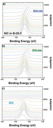
Two different approaches were used to split the different chemical states in the depth profiles. To determine the chemical states of silicon, Gauss-Lorenz peak fitting was used. In the depth profile of Si-DLC(0.0%O2)/CoCrMo the Si2s in the Si-DLC layer which consists of Si in a DLC matrix (cycle 9 in ) was determined to be at 151.73 eV (1.79 eV FWHM, where FWHM stands for full width at half maximum; 56% Gaussian contribution). The corresponding Si2p signal is located at 100.6 eV, which is therefore assigned to Si-C [Citation31]. With these values fixed, the additional signal appearing at the interface (cycle 15 in ) was fitted to be at 150.61 eV (1.81 eV FWHM, 60% Gauss). The corresponding Si2p signal, which shows interference with the Co3s signal, is at 99.5 eV. In this binding energy range only elemental silicon and metal-silicides are present; therefore this peak is assigned to metal silicides. Furthermore, these values do match with the literature values for CoSi, which are 150.8 eV for the Si2s and 99.5 eV for the Si2p signal [Citation32]. Analogously, with all these parameters fixed, the additional contribution in the samples deposited with 0.5 and 1.0% oxide in the plasma was fitted (cycle 15 and 11 in respectively) to be at 152.85 eV (2.68 eV FWHM, 90% Gauss). The corresponding Si2p signal is located at 101.8 and corresponds to Si-O bonds [Citation33]. The SiO2 signal at 103.5 eV was not detected.
The other core levels of the depth profiles have been separated into their different chemical states by linear least squares (LLS) spectral fitting. In this procedure provided by the MultiPak software two or more spectra are chosen as a reference of different chemical states. Then all spectra of the depth profile are fitted into their relative contribution to these reference spectra. As already published in the XPS analysis of a DLC/CoCrMo interface, where the reactively formed material at the interface was a (CoCrMo)1C0.5 compound, the Co2p and the Cr2p states do not show a chemical shift between the metallic and the carbidic state [Citation14]. Therefore, for analysis of metal compounds at the interface the Co3p, Cr3p as well as the Mo3d signals have been used. As reference for the metal interface compounds the first spectrum having adequate signal intensity was taken. For Co these interface state spectra show a shift of ca 0.5 eV to higher binding energy of 59.8 eV, with respect to the bulk metallic states of CoCrMo. According to the literature the Co3p is at 59.8 eV for the Co-C [Citation14] as well as for the CoSi compound [Citation32]. Therefore these cobalt interface states have not been split into metal carbides and metal silicides and these contributions are considered to be metal carbides and silicides. No metal-oxides have been seen in the Co2p and Cr 2p states on any of the depth profile. The C1s signal was split into the C state of the Si-DLC layer at 284.0 eV, composed of C in C-C and C-Si bonds, and the metal-carbide peak at the interface present at 283.0 eV. Our carbidic C1s peak position at 283.0 eV is in accordance with the peak position of the CoCrMo carbide measured on DLC/CoCrMo interface at a binding energy of 283.1 eV [Citation14].
3. Results and discussion
3.1. Local damage simulation: scratches
The added stresses concomitant with defects and cyclic loading may decrease the lifetime. Therefore, it is necessary to consider potential delamination start sites (e.g. pinholes, dust shadows, scratches, loose grains) [Citation28]. Considering that a fatigue crack usually starts at a stress concentration site, a simulated defect pre-defined as a scratch has been selected as the stress-riser at the coating surface. This study tracks the progress of pre-existing delamination sites via a controllable, reproducible and comparable damage-defect simulation performed as a scratch with a diamond tip. The aim begins to mimic a more realistic scenario where a reciprocating load in a corrosive media slides across, weakening the adhesion of the coating.
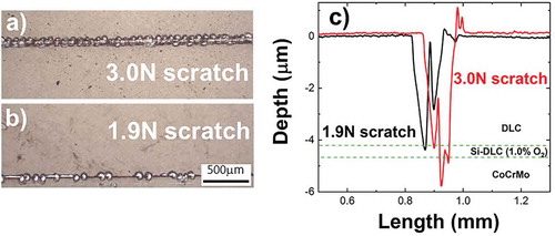
show an optical top view comparison of the pre-defined scratches achieved by applying 3.0 and 1.9 N, respectively, at a speed of 1 mm/s on DLC/Si-DLC(1.0%O2)/CoCrMo. For both loads, delamination spots are observed along the scratch with a dissimilar periodicity. As expected, the width (120, 190 μm) and depth (4.3, 5.7 μm) measured by profilometry are load dependent (), hence the straight implication is that the predamage intensity can be preselected and characterized in advance. Note the double sharp feature in both depth profiles, indicating a double vertex in the scratching diamond tip. Since the tip geometry has an influence on the scratch depth and width, the position of the tip was kept constant in all the experiments to assure reproducibility for comparative purposes of the exposed area to the electrolyte. Additionally, the influence of the tip speed on the scratch has been explored, selecting 1.0 mm/s because of the larger local damage provoked for the same load, as compared to 0.5 mm/s.
Figure 2. (a) Scratches on DLC/Si-DLC(1.0%O2)/CoCrMo created by applying 3.0 and 1.9 N with a diamond tip at 1 mm/s. (b) Depth profiles across the scratches. Dotted lines indicate the location depth of the Si-DLC(1.0%O2) interlayer.
The simulated damage dimensions affect as well the dynamic corrosion fatigue resistance of the interlayer. show the typically ellipsoidal shape wear tracks across the 3.0 N and 1.9 N scratches under the same sliding test conditions. Across the 3.0 N scratch, the test results in the failure of the coating-interlayer system, whereas across the 1.9 N scratch, the test slightly increases the delamination spots close to the scratch. While the remaining wear track is barely affected. This may be an indication of the influence the electrolyte has on the exposed interface which affects the corrosion fatigue performance.
Figure 3. Reciprocating sliding test across 3.0 N and 1.9 N scratches on DLC/Si-DLC(1.0%O2)/CoCrMo at 37 °C, in PBS, f = 12 Hz, 13,500 cycles, 4.5 N along 2 mm stroke length with an Al2O3 counterbody sphere, (a) Top view optical images of the wear tracks; (b) corresponding coefficient of friction.
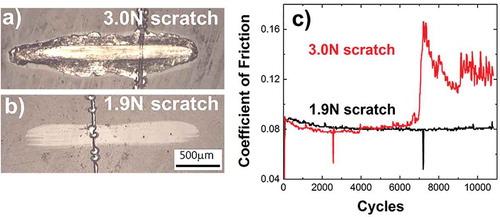
The coefficient of friction (CoF) of DLC/Si-DLC(1.0%O2)/CoCrCMo resides around 0.08 in the steady state () and before any detectable failure event such as: (i) sudden decrease in the CoF during 3–4 s (36–48 cycles), see spikes after 2000 and 7000 cycles in . Although there is no other experimental evidence, authors hypothesize that the fast drop in CoF may be associated to short time lack of contact between the rubbed surfaces due to the interaction with a delaminated DLC fragment until expelled from the contact; (ii) slight increase in CoF probably ascribed to the adhesion promoting interlayer failure (4000 cycles for 3.0 N in ); (iii) the remarkable increase in CoF as due to the total wear out of the coating and the contact between the counterbody and the substrate, that is, sliding of the alumina sphere against CoCrMo with no appreciable contribution of any remaining coating (>7000 cycles for 3.0 N in ). There are in both CoF curves events which cause the lack of measurement for short times (negative spikes). One plausible explanation is the generation of a third body which acts as a sliding surface inhibiting the contact sphere-coating for microseconds, further leading to the lack of measurements observed in the graphs. On the following, all the presented results are reciprocated across the severer simulated damage, 3.0 N–1 mm/s scratch, in order to place the experiments at the highest load at the interface and expose both the interface and the substrate to the corrosive fluid. Due to unwanted experimental geometrical limitations, in some occasions the wear track was not perpendicular to the scratch, and therefore smaller variations of the load at the interface are expected.
3.2. Realistic boundaries to accelerate the corrosion fatigue lifetime prediction for interface delamination
3.2.1. Frequency
The acceleration of an interface delamination lifetime prediction requires high frequencies and therefore protein denaturation processes are highly probable. Under these circumstances, the role played by denatured proteins is only addressed as a preliminary study. In the same sense, a prescreening study over a frequency range has been performed to determine to which extent the corrosion fatigue lifetime prediction of the interface can be accelerated. The present research explores as well any frequency related effect that may influence the load at the interface.
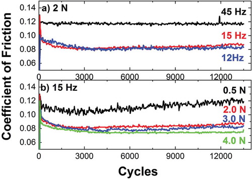
As can be seen in , the CoF is frequency dependent. For a certain load, the CoF(0.12) at 45 Hz is higher than at 12–15 Hz, CoF(0.08). A feasible explanation causing the increased CoF with frequency may have three contributions: (i) liquid partially pushed out, reducing the water lubricant effect; (ii) higher wear on the counter sphere, ascribed to the larger sliding distance at the end of the test; and (iii) higher hydrodynamic resistance of the moving alumina sphere, generating an additional tangential force. Contributions i and ii increase the load at the interface. Moreover, the CoF at 12Hz is similar to the CoF at 15 Hz and therefore, the load at the interface can be considered equivalent. Additionally, for a constant frequency of 15 Hz, the CoF slightly decreases with the normal load (), in agreement with previous studies [Citation34]. Consequently, 15 Hz has been selected as a suitable frequency which would allow the analysis of corrosion fatigue in the whole range of normal loads available in the experimental setup (0.5–10.0 N), accelerating the testing time a factor of 15, as compared to the 1 Hz employed in certified simulators (ISO14242).
Figure 4. CoF in DLC/Si-DLC(1.0%O2)/CoCrMo across 3 N–1 mm/s scratch in PBS at 37 °C with Al2O3 sphere at (a) 2 N normal load; (b) frequency of 15 Hz.
3.2.2. Selection of the body-like fluid media
In order to select a representative physiological environment which enhances the corrosion fatigue processes, comparative reciprocating sliding experiments along 13,500 cycles were performed in several media () while accounting for the potential friction and corrosion fatigue influence of water, inorganic salts and biological molecules: humid air (50% RH, relative humidity), Milli-Q® water (MQ), NaCl solution (0.14 M, NaCl diluted in MQ), Ringers’ solution, PBS, and bovine calf serum (Hyclone®) diluted in PBS to achieve a protein concentration of 34 g/l.
Figure 5. Top view of wear tracks after a reciprocating sliding test across a 3 N–1 mm/s scratch on DLC/Si-DLC(1.0%O2)/CoCrMo at 37 °C, 15 Hz, 5 N normal load, 13,500 cycles along 2 mm against an alumina sphere in (a) ambient air (50% RH); (b) MQ water; (c) 0.14 M NaCl; (d) Ringers’ solution; (e) PBS; (f) Bovine calf serum diluted in PBS with a protein concentration of 34 g/l.
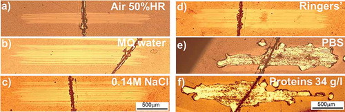
Despite the fact that under physiological conditions, the implants are not solely exposed to pure salt solutions but to protein containing serum, the influence of isolated salts was evaluated by running an experiment in a NaCl solution with the same concentration as in PBS (0.14 M). As there was no delamination, it can be stated that NaCl salts does not trigger delamination by corrosion fatigue at the tested conditions. The phosphate containing solutions showed delamination, as can be seen in . These results suggest that phosphate containing solutions play a major role when present in dynamic performance. In contrast, salts such as NaCl, or carbonates (0.0024 M) present in Ringers’ solution do not trigger the tribo-corrosion delamination at the interface. Conversely, in PBS () an enhanced tribo-chemical reaction triggers delamination. Further experiments that exceed the scope of this research are needed to have a deeper understanding about the corrosive reactions taking place at the interface. A correlation to the influence of phosphates in the corrosion of silicon in confined spaces will be published by Ilic et al.
The protein concentration in the testing fluid for artificial joints affects the lubricant properties and in consequence is relevant in determining the susceptibility to delamination. Reciprocating sliding across the simulated damage was performed in bovine calf serum Hyclone® diluted in PBS up to a protein concentration of 34 g/l, which corresponds to an albumin concentration around 14 g/l, representative in human interstitial fluid which comes out from the cartilage when high loads are applied [Citation35]. Note as well that an average protein concentration of 30 g/l was reported for human patients with artificial articulating prosthesis and is used as a standard representative concentration in spinal disk simulations [Citation28]. The protein containing media leads to enhanced delamination. However, as the media is diluted with PBS in order to achieve a realistic concentration, the influence of proteins is not possible to isolate. Consequently, PBS has been selected as a good candidate at this stage of the research to address corrosion fatigue at the interface.
Summarizing, shows the strong influence the media has on coating delamination, and supports the assumption of considering the methodology in PBS as an effective corrosion fatigue fluid for accelerating the articulating implants lifetime prediction for the DLC/Si-DLC/CoCrMo system.
shows the recorded coefficients of friction corresponding to the tests illustrated in . The CoF in the absence of liquid remains at CoF(0.1), whereas when water-based liquid or bovine calf serum fluid is present, several differences arise. On average the coefficient of friction in the presence of water based testing fluid is lower and more stable than in humid air at 50% relative humidity, RH, which can be attributed to water induced lubrication regime [Citation36–Citation38]. In addition, the removal of wear debris in a fluid can contribute to a smaller CoF; the diluting effect exerted by the fluid decreases entrapped wears debris which can abrade the contact area. It is also important to bear in mind that the reduction in friction of DLC-SiO can be associated as well with tribochemical reactions, that is, gas reactions with a mechanically stressed sp2 carbon rich surface layer, pointed out by Koshigan et al. [Citation39]. Although the higher CoF in 50% RH accounts for higher load at the interface, lower wear and absence of delamination was detected in the so called dry conditions, in contrast with the water based body-like fluids, visible in . Increased delamination under water lubrication as compared to dry rubbing, is a known behavior ascribed to the formation of low energy surfaces by the adsorbed water at the dangling carbon bonds [Citation37,Citation40]. Note that as the surface roughness is the same in all the cases, the failure can be addressed to the corrosion fatigue triggered by the fluid.
Figure 6. Coefficients of friction from reciprocating sliding tests across 3 N–1 mm/s scratch in DLC/Si-DLC(1.0%O2)/CoCrMo at 37 °C, 15 Hz, 5 N normal load, 13,500 cycles along 2 mm against an alumina sphere corresponding to 50% HR, PBS, MQ water, 0.14M NaCl, and bovine calf serum with 34 g/l protein concentration.
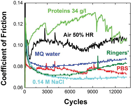
On the other hand, the CoF in Ringers’ solution shows an increase with loading time, probably ascribed to higher wear detected on the counterface surface. This explanation is suitable as well for the case of a higher CoF in MQ water than in 0.14 M NaCl. When bovine calf serum is present, the CoF is substantially higher. The effect might be attributed to the high-shear-strength layer at the surface provided by denatured proteins upon adsorption which weaken the lubrication [Citation41,Citation42], favoring a mixed boundary-liquid lubrication mechanism [Citation28]; and to the increased wear at the counterpart.
Finally, it is important to remark that illustrates why the CoF cannot be used as the sole delamination evaluation criteria, since even in the case of a severely delaminated system (, PBS), no clear correlation between the delamination event and the CoF can be observed in the first stages.
3.3. Wöhler-like curve: accelerated corrosion fatigue of an interface
3.3.1. Interface failure criteria
To assess the failure of the interlayer in the vicinity of the simulated damage the authors have followed visual inspection criteria. As an illustrative example, displays the difference between successful essays when performed in Milli-Q water, NaCl solution, Ringers’ solution ( respectively), and essays performed in body-like fluid (37 °C, 50% relative humidity, RH) such as PBS () or with a certain protein concentration in bovine calf serum (). In the case of interface failure () a bright area corresponding to the reflection of the light in the CoCrMo substrate is clearly visible. Note that although the delamination spots mainly propagate from the simulated damage (scratch), they also take place at several positions along the wear track. It has been observed that these later delamination spots usually appear after delamination has been initiated from the initial scratch. Therefore a reasonable assumption is to consider that the initial wear debris at the weakest site of the system propagates further delamination in a sort of avalanche process. According to the visual failure interface criteria, and considering that once the delamination has been initiated it is propagated along the wear track, will be considered as failed interfaces.
3.3.2. Cumulative fatigue damage
The phenomenon that leads to the failure of an interface under simultaneous action of cyclic loads and chemical interaction is assigned in this article to corrosion fatigue. Typically, the corrosion fatigue of a bulk material is described by stress cycles to failure, S-N, or Wöhler curves. A highly localized plastic deformation during cyclic loading results in alteration of the material’s properties, leading to crack initiation and growth. The Wöhler curve represents the number of cycles needed to concentrate the plastic strain leading to crack initiation, growth, and subsequent material fatigue failure. A corrosive media can contribute to and accelerate the initiation time in a combined corrosion fatigue activity, and modify the endurance limit. In this study, similar corrosion fatigue failure concepts are adapted to the particular case of a buried interface. Instead of describing the critical stress, the proposed Wöhler-like curve considers the load at the interface. The justification is that the induced tangential force during the reciprocating sliding (Load·CoF) is proportional to the shear strength at the interface. Summarizing, this research proposes a fatigue-wear setup as the experimental methodology to introduce shear forces at the interface and therefore it will be used unconventionally to address the interface corrosion fatigue.
The experimental Wöhler-like curves for the three different Si-DLC/CoCrMo interfaces are illustrated in , summarizing the results of the critical load needed for the interface corrosion fatigue failure as a function of loading cycles. To determine the critical load, Lc, at which interface failure under corrosion fatigue took place, reciprocating sliding tests were performed across a scratch. The normal load was increased at intervals of 0.5 N, up to the load at which an enhanced delamination at the vicinity of the induced scratch was detected by visual inspection under the microscope. contains only the detected Lc values, and therefore all the experimental data corresponding to essays after which the delamination was not enhanced, are not included in the Wöhler-like graph for clarity purposes. It is important to remark that the omitted experiments were necessary steps for determining the critical load, mainly for two reasons: (i) this methodology can trace the wear track evolution and therefore the critical load at which delamination starts limited by the incremental steps of the experimental device, in our particular case, 0.5 N; (ii) another approach was evaluated: the experiment was intentionally stopped and, after visual checking, continued. This approach was discarded because the discontinuity leads to a decrease in the CoF which affects the shear strength at the interface.
Figure 7. Wöhler-like curve of the Si-DLC/CoCrMo interface vs Al2O3 at 15 Hz and 37 °C in PBS. The dotted lines present fitting results using EquationEquation (1)(1)
(1) .
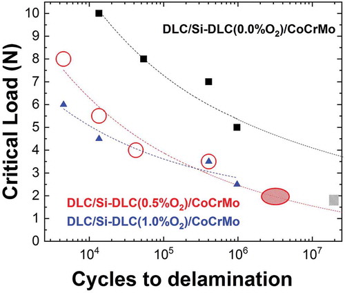
The Wöhler-like curves in show that the absence of oxygen places the L-N curve above those corresponding to oxygen containing interfaces, which indicates that the presence of oxygen decreases the fatigue life and endurance limit. The points on the graph correspond to the experimental Lc data whereas the dotted lines are the L-N curves fittings according to the empirical condition revealed in 1914 by Stromeyer [Citation43]:
Where Le is the extrapolated endurance limit, A is a coefficient affecting the endurance, and Lc is the nominal load required to cause the interface delamination after N reciprocating sliding cycles. summarizes the values obtained from the fitted L-N curves. Although additional experimental data would improve the fitting quality and reduce errors, the trend already gives an indication of the interface lifetime prediction under corrosion fatigue. Note the substantially higher endurance limit Lc for the interface with no contaminant oxygen, as compared to the Lc when oxygen is present. The predicted crossing of fitted curves DLC/Si-DLC(x%O2)/CoCrMo (x = 0.0 and 0.5%O2) remains under the calculated errors and therefore do not incur any contradiction. Conversely, the predicted A coefficients are proportional to the oxygen content. Therefore the combination of both trends evidences that the presence of oxygen decreases the lifetime of the interface Si-DLC/CoCrMo under corrosion fatigue.
Table 1. Summary of fitted parameters from the Wöhler-like curve (1) of the interfaces DLC/Si-DLC(X%O2)/CoCrMo, X = 0.0, 0.5, and 1.0%O2.
It is important to bear in mind that the influence of body-like media could lead to modify, or even eliminate the endurance limit of the interfaces. However, the fitting from Equationequation (1)(1)
(1) can be further used to link these experiments with the lifetime results of the coatings tested in the ball-on-socket spinal disk simulator [Citation28]. Therefore, the information contributes to the description of the simulated physiological conditions to achieve reliable information on the long-term behavior of the implant. According to the fitting, the sample DLC/Si-DLC(0.5%O2)/CoCrMo that started to delaminate after 2–5 million cycles in the spinal disk simulator (), would have a similar delamination pattern in the reciprocating sliding setup at a load around 2 N. Therefore, a striped oval has been placed in as a semiquantitative result, connecting the two experimental results through the Wöhler-like curve fitting. Conversely, the DLC/Si-DLC(0.0%O2)/CoCrMo coating did not delaminate after 20 million cycles in the spinal disk simulator, and therefore only a striped square has been placed below the corresponding Wöhler-like curve. The detailed simulator results are in preparation in a dedicated article.
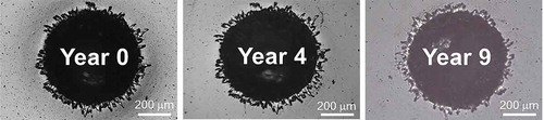
It is interesting to add that after more than 9 years immersed in PBS at 37 °C, these coatings do not present stress corrosion cracking, as can be seen in the photos made along the years on the Rockwell indentations performed in DLC/Si-DLC(0.5%O2)/CoCrMo (). Therefore, we can conclude that the observed delamination enhanced by the reciprocating sliding test is mainly related to corrosion fatigue, validating the described methodology to address corrosion fatigue phenomena at interfaces.
Figure 8. Top view images of the same Rockwell indentation on 4 μm DLC/Si-DLC(0.5%O2)/CoCrMo coating deposited by RF-CVD, immersed in PBS for 9 years.
3.4. Plastic deformation by corrosion fatigue
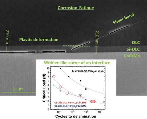
A SEM image of a DLC/Si-DLC(1.0%O2)/CoCrMo cross-section is shown in . The longitudinal FIB cut was performed along the sliding direction, on a delamination generated in PBS at 37 °C, 12 Hz, applying 4N after 13,500 cycles. A crack is formed, approximately 8 μm in length, along the Si-DLC(1.0% O2)/CoCrMo interface resulting in a much higher load acting on the still adhering zones nearby. During dynamic deformation of the system the weakest interface fractures, probably enhanced by the corrosive media. In contrast, the Si-DLC(1.0%O2)/DLC interface do not present any crack parallel to the substrate. Furthermore, as a result of highly plastically deformed areas, shear bands are formed across the Si-DLC(1.0%O2)/DLC interface, and propagate thorough the DLC (). The shear banding itself evidences that the amorphous carbon matrix undergoes plastic deformation associated with fatigue. Similarly as in the case of amorphous metals, the deformation is associated to a local rearrangement of atoms to accommodate shear strain [Citation44]. The shear bands appear at an angle of 28°. A possible explanation as to why the angle appears to be smaller than 45°, is the superimposed compression of loading to the pure shear tension. The plastic deformation of the Si-DLC(1.0%O2) layer is clearly visible as well, supporting the fatigue regime hypothesis. Besides, the invariance in thickness of Si-DLC(1.0%O2) layer above the crack and after the shear band (), verifies that there is no material dissolution and supports the fracture assumption after plastic deformation. As can be seen at the end of an open crack in the DLC (), the shear band formation precedes the crack formation. Discontinuous cracks on similar DLC coatings were previously detected in tests performed after 100 million cycles in a spinal disk simulator [Citation13]. This study proposes that the continuous fatigue deformation boosts the highly localized plastic deformation of the carbon matrix, leading to crack formation at several locations. If the dynamic loading continues, the cracks eventually connect leading finally to coating delamination.
Figure 9. SEM cross-section of a delamination observed in DLC/Si-DLC(1.0%O2)/CoCrMo after 13,500 cycles in PBS at 37 °C, 12 Hz and 4 N. (a) Overview; (b) beginning of a shear band at the end of a crack at the interface Si-DLC/CoCrMo; (c) cavities at the end of a shear band in DLC. The thickness of the Si-DLC interlayer is marked by arrows (210 nm).
Using finite element calculations it could be shown that at the edge of the crack on the Si-DLC/CoCrMo interface, a tensile stress is induced when the alumina sphere slides over the surface. These results will be published in a dedicated article.
3.5. Composition of the interface
The decrease in the corrosion fatigue resistance with increasing amount of oxygen is likely connected with internal modifications of microstructure and therefore with mechanical properties. To determine the composition of materials formed at interfaces, we have prepared samples with a thickness of 15 nm and examined them by XPS depth profiling. The profiles are shown in .
Figure 10. XPS depth profiles chemical composition of interfaces (a) Si-DLC(0.0%O2)/CoCrMo; (b) Si-DLC(0.5%O2)/CoCrMo; and (c) Si-DLC(1.0%O2)/CoCrMo performed in 15 nm thickness coatings.
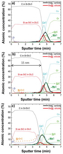
For interpretation of the depth profiles, it has to be considered that the original interface state may have been altered by the 2 kV argon ions used for material removal during depth profiling. However, the samples have been produced by plasma deposition at −600 V self-bias voltage, which is also much more energy per ion than an average chemical bond. Therefore during depth profiling, although higher ion energy is used then during deposition, the reactively formed interface may appear slightly wider but is still to a large extent displaying its original chemical situation. For example a C/Si interface with only 0.3 nm SiC present, determined by non-destructive angle resolved XPS, will show ca. 3 nm SiC at the interface when analyzed in a depth profile using 3 kV Ar ions [Citation45]. Therefore, when the depth profile the interfaces using 2 kV Ar ions is performed, it is estimated that up to 2 nm of the total 5 nm reactively formed interface material may have been generated by the depth profile analysis. So the interface compositions presented here can be considered semi-quantitative only, however, they still allow a comparison between the different samples.
The pure DLC/CoCrMo interface, published previously, showed a carbidic interface of ca. 5 nm extension and a stoichiometry close to (CoCrMo)2C [Citation14]. This interface material showed a severe sensitivity to stress corrosion cracking (SCC), resulting in film delamination in the presence of water or even humidity [Citation16,Citation17]. The depth profiles on the Si-DLC/CoCrMo interfaces () show beside the metal-carbides an additional contribution of metal-silicides of comparable intensity. It appears that the carbides are more extended into the interface than the silicides. It is not clear if the extended carbide signal is real or additional carbides have been generated by the Ar sputtering during depth profile analysis. Therefore, the stoichiometry of this interface material is approximately Me2CSi0.8. The interface Si-DLC(0.0%O2)/CoCrMo with the additional silicide compound did not show any sensitivity to SCC, and did not show any delamination even under high load. It also showed good performance when tested on articulating joints in a spinal disk simulator up to 20 million articulations (results in preparation). This clearly demonstrates that a change in the interface composition can have a drastic effect on the corrosion stability and therefore on the coating adhesion behavior.
As seen in respectively, the addition of 0.5 and 1.0% oxygen contamination during the deposition process results in an additional Si-O compound, mainly visible in the 1.0% interface (). Also, there is a reduced amount of metal-silicides at the Si-DLC(1.0%O2)/CoCrMo interface. It seems that Si species, when they are oxidized, are not available any more for the formation of metal-silicides during the deposition process. Therefore, we conclude that the beneficial effect of metal silicides, in preventing coating delamination by SCC of the interface material, is diminished by the addition of oxygen. However, we also cannot exclude that the addition of the Si-O species at the interface is increasing the sensitivity toward SCC, or any other form of deterioration.
Figure 11. Stack plot of XPS depth profiles of (a) Si-DLC(0.0% O2)/CoCrMo; (b) Si-DLC(0.5% O2)/CoCrMo; and (c) Si-DLC(1.0% O2)/CoCrMo.
4. Conclusions
This study of the boundaries created to accelerate interface corrosion fatigue by dynamic loading demonstrates that the predamage scratch dimensions, the frequency and the media strongly affect the interface lifetime performance. A frequency of 15 Hz and a corrosive media containing phosphates, such as PBS, were chosen as the better candidates to accelerate corrosion fatigue with stability of CoF for the load range studied (0.5–10N). The interfaces show a Wöhler-like curve in their corrosion fatigue. The properties of materials created at the interfaces change during corrosion fatigue experiments. The higher oxygen content weakens the corrosion fatigue resistance of the coating. In addition, it has been experimentally demonstrated that both the interface Si-DLC/CoCrMo and the DLC coating show plastic deformation along the sliding direction. The Wöhler-like behavior and the experimental evidence of plastic deformation validate the proposed corrosion fatigue setup as an experimental methodology to introduce shear forces at the interface. The corrosion fatigue methodology can be applied to any interface as long as an appropriate media is used. However, this test accelerates only interface corrosion fatigue causing delamination. Other deterioration effects such as crevice corrosion, stress corrosion cracking, electro-corrosion, and dissolution have to be addressed and accelerated separately.
Acknowledgments
The authors would like to express their gratitude to Bernhard Weisse, Sigfried Roos, Christian Affolter and Rowena Crockett for helpful discussions and comments.
Disclosure statement
No potential conflict of interest was reported by the authors.
Additional information
Funding
References
- Manley MT, Sutton K. Bearings of the future for total hip arthroplasty. J Arthroplasty. 2008;23(7):47–50.
- Della Valle AG, Becksaç B, Anderson J, et al. Late fatigue fracture of a modern cemented forged cobalt chrome stem for total hip arthroplasty: A report of 10 cases. J Arthroplasty. 2005;20(8):1084–1088.
- Bewilogua K, Hofmann D. History of diamond-like carbon films-From first experiments to worldwide applications. Surf Coat Tech. 2014;242:214–225.
- Love CA, Cook RB, Harvey TJ, et al. Diamond like carbon coatings for potential application in biological implants—a review. Tribol Int. 2013;63:141–150.
- Akaike S, Kobayashi D, Aono Y, et al. Relationship between static friction and surface wettability of orthodontic brackets coated with diamond-like carbon (DLC), fluorine- or silicone-doped DLC coatings. Diam Relat Mater. 2016;61:109–114.
- Nam ND, Lee SH, Kim JG, et al. Effect of stress on the passivation of Si-DLC coating as stent materials in simulated body environment. Diam Relat Mater. 2009;18(9):1145–1151.
- Hauert R. A review of modified DLC coatings for biological applications. Diam Relat Mater. 2003;12(3):583–589.
- Hauert R, Thorwarth K, Thorwarth G. An overview on diamond-like carbon coatings in medical applications. Surf Coat Tech. 2013;233(SupplementC):119–130.
- Taeger G, Podleska LE, Schmidt B, et al. Comparison of diamond-like-carbon and alumina-oxide articulating with polyethylene in total hip arthroplasty. Materialwissenschaft und Werkstofftechnik. 2003;34(12):1094–1100.
- Joyce TJ. Examination of failed ex vivo metal-on-metal metatarsophalangeal prosthesis and comparison with theoretically determined lubrication regimes. Wear. 2007;263(7):1050–1054.
- Hauert R, Falub CV, Thorwarth G, et al. Retrospective lifetime estimation of failed and explanted diamond-like carbon coated hip joint balls. Acta Biomater. 2012;8(8):3170–3176.
- Hauert R, Thorwarth G, Müller U, et al. Analysis of the in vivo failure of the adhesive interlayer for a DLC coated articulating metatarsophalangeal joint. Diam Relat Mater. 2012;25:34–39.
- Thorwarth K, Thorwarth G, Figi R, et al. On interlayer stability and high-cycle simulator performance of diamond-like carbon layers for articulating joint replacements. Int J Mol Sci. 2014;15(6):10527–10540.
- Mueller U, Falub CV, Thorwarth G, et al. Diamond-like carbon coatings on a CoCrMo implant alloy: A detailed XPS analysis of the chemical states at the interface. Acta Mater. 2011 Feb;59(3):1150–1161.
- Hauert R. DLC films in biomedical applications. In: Donnet C, Erdemir A, editors. Tribology of diamond-like carbon films: fundamentals and applications. Boston (MA): Springer US; 2008. p. 494–509.
- Falub CV, Mueller U, Thorwarth G, et al. In vitro studies of the adhesion of diamond-like carbon thin films on CoCrMo biomedical implant alloy. Acta Mater. 2011;59(11):4678–4689.
- Falub CV, Thorwarth G, Affolter C, et al. A quantitative in vitro method to predict the adhesion lifetime of diamond-like carbon thin films on biomedical implants. Acta Biomater. 2009 Oct;5(8):3086–3097.
- Cemin F, Boeira CD, Figueroa CA. On the understanding of the silicon-containing adhesion interlayer in DLC deposited on steel. Tribol Int. 2016;94:464–469.
- Hutchinson JW, He MY, Evans AG. The influence of imperfections on the nucleation and propagation of buckling driven delaminations. J Mech Phys Solids. 2000;48(4):709–734.
- Yu HH, He MY, Hutchinson JW. Edge effects in thin film delamination. Acta Mater. 2001;49(1):93–107.
- Xie ZH, Singh R, Bendavid A, et al. Contact damage evolution in a diamond-like carbon (DLC) coating on a stainless steel substrate. Thin Solid Films. 2007;515(6):3196–3201.
- Staia MH, Puchi-Cabrera ES, Iost A, et al. Sliding wear of a-C:H coatings against alumina in corrosive media. Diam Relat Mater. 2013;38:139–147.
- Teoh SH. Fatigue of biomaterials: a review. Int J Fatigue. 2000;22(10):825–837.
- Schaufler J, Durst K, Haas T, et al. The influence of hydrogenated amorphous carbon coatings (a-C:H) on the fatigue life of coated steel specimens. Int J Fatigue. 2012;37:1–7.
- Sundaram VS. Diamond like carbon film as a protective coating for high strength steel and titanium alloy. Surf Coat Tech. 2006;201(6):2707–2711.
- Puchi-Cabrera ES, Staia MH, Ochoa-Pérez EA, et al. Fatigue behavior of a 316L stainless steel coated with a DLC film deposited by PVD magnetron sputter ion plating. Mater Sci Eng A. 2010;527(3):498–508.
- Laribi MA, Tamboura S, Fitoussi J, et al. Fast fatigue life prediction of short fiber reinforced composites. Int J Innov Res Sci Eng Technol. 2015;4(5):3659–3664.
- Thorwarth G, Falub CV, Müller U, et al. Tribological behavior of DLC-coated articulating joint implants. Acta Biomater. 2010;6(6):2335–2341.
- Crockett R. Boundary lubrication in natural articular joints. Tribol Lett. 2009;35(2):77–84.
- Igual Munoz A, Schwiesau J, Jolles BM, et al. In vivo electrochemical corrosion study of a CoCrMo biomedical alloy in human synovial fluids. Acta Biomater. 2015;21:228–236.
- Hauert R, Muller U, Francz G, et al. Surface analysis and bioreactions of F and Si containing a-C:H. Thin Solid Films. 1997;308:191–194.
- Zhao J, Poirier DM. Characterization of cobalt silicide formation by X-ray photoelectron spectroscopy. I CoSi Surf Sci Spectra. 2000;7:322–328.
- Lopez JAL, Lopez JC, Valerdi DEV, et al. Morphological, compositional, structural, and optical properties of Si-nc embedded in SiOx films. Nanoscale Res Lett. 2012;7:1–10.
- Pardo A, Gómez-Aleixandre C, Celis JP, et al. Friction and wear behavior of plasma assisted chemical vapor deposited nanocomposites made of metal nanoparticles embedded in a hydrogenated amorphous carbon matrix. Surf Coat Tech. 2012;206(13):3116–3124.
- Bruinink A. Handbook of Biomaterials. New York (NY): John Wiley & Sons Inc; 2019.
- Tokoro M, Aiyama Y, Masuko M, et al. Improvement of tribological characteristics under water lubrication of DLC-coatings by surface polishing. Wear. 2009;267(12):2167–2172.
- Sutton DC, Limbert G, Stewart D, et al. The friction of diamond-like carbon coatings in a water environment. Friction. 2013;1(3):210–221.
- Zhang TF, Xie D, Huang N, et al. The effect of hydrogen on the tribological behavior of diamond like carbon (DLC) coatings sliding against Al2O3 in water environment. Surf Coat Tech. 2017;320:619–623.
- Koshigan KD, Mangolini F, McClimon JB, et al. Understanding the hydrogen and oxygen gas pressure dependence of the tribological properties of silicon oxide–doped hydrogenated amorphous carbon coatings. Carbon. 2015;93:851–860.
- Jiang J, Zhang S, Arnell RD. The effect of relative humidity on wear of a diamond-like carbon coating. Surf Coat Tech. 2003;167(2):221–225.
- Roba M, Naka M, Gautier E, et al. The adsorption and lubrication behavior of synovial fluid proteins and glycoproteins on the bearing-surface materials of hip replacements. Biomaterials. 2009;30(11):2072–2078.
- Munoz AIMS. Interactive effects of albumin and phosphate ions on the corrosion of CoCrMo implant alloy. J Electrochem Soc. 2007;154(10):562–570.
- Stromeyer CE. The determination of fatigue limits under alternating stress conditions. Proc R Soc Lon Ser A. 1914;90(620):411–425.
- Park ES. Understanding of the shear bands in amorphous metals. Appl Microsc. 2015;45(2):63–73.
- Zehringer R, Hauert R. Depth profile analysis of the C/Si interface-Comparison of destructive and nondestructive techniques. Surf Sci. 1992;262(1–2):21–24.