?Mathematical formulae have been encoded as MathML and are displayed in this HTML version using MathJax in order to improve their display. Uncheck the box to turn MathJax off. This feature requires Javascript. Click on a formula to zoom.
ABSTRACT
The plastic deformation behavior of single crystals of α-Nb5Si3 with the tetragonal D8l structure has been investigated by micropillar compression at room temperature as a function of crystal orientation and specimen size. Three slip systems, (001)<010>, {110}<10> and {0
1}<111>, are found to be operative in micropillar specimens of α-Nb5Si3 single crystals at room temperature, as in the case of isostructural Mo5SiB2. The CRSS values obtained for the three slip systems are extremely high above 2.0 GPa and exhibit the ‘smaller is stronger’ trend, which can be approximated by the inverse power-law relationship. The fracture toughness evaluated by single-cantilever bend testing of a chevron-notched micro-beam specimen is 1.79 MPa m1/2, which is considerably lower than that (2.43 MPa m1/2) reported for isostructural Mo5SiB2. The selection for the dissociation schemes and possible glide planes for dislocations of the three slip systems is discussed based on generalized stacking fault energy (GSFE) curves theoretically calculated by first-principles calculations.
GRAPHICAL ABSTRACT

CLASSIFICATION:
1. Introduction
There is a strong demand in recent years on the reduction of carbon dioxide emissions to slow down the rate of global warming. In view of the fact that carbon dioxide emissions are due mostly to fossil fuel burning, the thermal efficiency improvement of various combustion systems including those used in power generation and transportations is considered to be one of the most realistic solutions for the reduction of carbon dioxide emissions. In order to improve the thermal efficiency of gas-turbine systems used in power plants and transportations, further increase in the turbine inlet temperature above 1600°C is required. To achieve this, the development of novel structural materials that can endure at such high temperatures is mandatory, since the temperature for this demand is far beyond the upper limit for Ni-based superalloys (melting temperature: around 1400°C) currently used in the hottest sections of gas turbine systems [Citation1,Citation2]. Nb-silicide based alloys have been considered as one of the promising candidates for some decades because of their high melting temperatures above 1700°C, high strength, and very good fracture toughness achieved mainly by the inclusion of the ductile Nb solid-solution phase [Citation3–6]. Most Nb-silicide based alloys so far developed consist of the ductile Nb solid-solution phase and the Nb5Si3 strengthening phase with high stiffness. While the high strength (especially at high temperatures) is achieved by the Nb5Si3 strengthening phase, the brittleness of developed alloys arising from Nb5Si3 has been a drawback in the development history of Nb-silicide based alloys. Nb5Si3 crystalizes into two polymorphs; α-Nb5Si3, a low temperature form with the tetragonal D8l structure (tI32, space group: I4/mcm, a = 0.657 nm, c = 1.1884 nm [Citation7]) and β-Nb5Si3, a high temperature form with the D8m structure (tI32, space group: I4/mcm, a = 1.0026 nm, c = 0.50717 nm [Citation7]), with polymorphic transition occurring approximately at 1700°C. It is α-Nb5Si3 that has been used for the strengthening phase of Nb-silicide based alloys. However, mechanical properties of monolithic α-Nb5Si3 have remained largely unknown, mainly because of the difficulty in single crystal preparation due to the β-α polymorphic transformation. There is only one report on plastic deformation behaviors of α-Nb5Si3 studied with Nb-Nb5Si3 two-phase polycrystalline alloys with Ti addition [Citation8]. Two types of dislocations having the Burgers vectors of <100> and 1/2 < 111> were observed by transmission electron microscopy (TEM) in α-Nb5Si3 in Ti-alloyed Nb-Nb5Si3 two-phase alloys deformed at 1400°C. Three slip systems, {01}<111>, {100}<010> and {001}<010> were inferred to be operative in α-Nb5Si3 based on trace analysis of dislocation line vectors in the TEM [Citation8]. In view of the fact that significant dislocation climb occurs at high temperatures during and after mechanical testing, however, slip system identification with the trace analysis method in the TEM has its own limitation for the accuracy. Moreover, critical resolved shear stress (CRSS) for these slip systems has never been evaluated.
Recently, we have investigated deformation behavior of various materials including hard and brittle materials such as 6H-SiC by utilizing the micropillar compression method [Citation9–19] and have found that plastic deformation indeed occurs in some of these hard and brittle materials even at room temperature when the specimen size becomes smaller down to micrometer scale [Citation10–12,Citation16–18]. Mo5SiB2 is one of the hard and brittle materials we tested by micropillar compression [Citation17]. Mo5SiB2, which is isostructural with α-Nb5Si3, has also been considered as the strengthening phase (called T2 phase) of Mo-Mo5SiB2 based alloys, which have attracted research interest in recent years as a candidate for new ultra-high temperature structural materials [Citation2]. In Mo5SiB2, we successfully identified three operative slip systems, (001)<100>, {110}<10> and {0
1}<111>, at room temperature through surface trace analysis and TEM analysis of dislocation structures, and evaluated their CRSS values [Citation17]. This clearly indicates the usefulness of micropillar compression testing for identification of operative slip systems and their CRSS values.
In this study, we investigate the room-temperature plastic deformation behavior of α-Nb5Si3 with the tetragonal D8l structure by compression tests of single crystalline micropillar specimens as a function of loading axis orientation and specimen size in order to identify the operative deformation modes and to evaluate their CRSS values. We calculate generalized stacking fault energy (GSFE) curves for possible slip systems by first-principles density functional theory (DFT) calculations in order to interpret the experimental results obtained by micropillar compression tests and to discuss the similarities and differences between two isostructural silicides, α-Nb5Si3 and Mo5SiB2.
2. Experimental procedure
Rod ingots in the stoichiometric composition (Nb-37.5 at.%Si) were prepared from high-purity Nb and Si by Ar arc-melting. A single crystal of high-temperature modification of Nb5Si3 (β-Nb5Si3) of approximately 5 mm in diameter and 70 mm in length was grown from the rod ingots using an optical floating-zone furnace equipped with a Xe-arc lamp as a heat source (FZ-20065XHV, Vacuum Metallurgical Co., Ltd., Japan) at a growth rate of 20 mm h−1 under Ar gas flow. The single crystal of β-Nb5Si3 was heat-treated at 1500°C for 96 hours to obtain a polycrystal of α-Nb5Si3 formed through the β-α polymorphic transformation. A polycrystalline ingot thus obtained consisted of relatively large grains of about 40 to 80 μm in diameter. A rectangular parallelepiped specimen was cut from the ingot, and the specimen surfaces were mechanically polished with 1 µm diamond paste and finished with colloidal silica. Crystallographic orientations of α-Nb5Si3 grains appeared on the finished surface were analyzed by electron backscatter diffraction (EBSD) in a scanning electron microscope (SEM) equipped with a field-emission gun (JSM-7001FA, JEOL, Japan) operated at 20 kV. Four different loading axis orientations, [021], [010], [001] and [10] were selected as in our previous micropillar compression tests for isostructural Mo5SiB2 [Citation17]. The largest Schmid factors for some possible slip systems selected based on the magnitude of Burgers vectors are listed in . Micropillar specimens with a square cross-section (edge length L ranging from 0.7 to 5 μm) and a height-to-edge length ratio of approximately 2 ~ 3 ([021], [010], and [
10] orientations) and 3 ~ 4 ([001] orientation) were fabricated from grains with their surface normal parallel to the selected loading axis orientations (within 2 degree deviation from the exact orientations) with a focused ion beam (FIB) machine (JIB-4000, JEOL, Japan) at an operating voltage of 30 kV. The relatively high height-to-edge length ratio was taken for the [001] orientation so that the possible slip systems ({0
1}<111> and {1
2}<111>, see ) can be activated within the gauge section as in the case of isostructural Mo5SiB2 [Citation17]. Micropillar compression tests were conducted at room temperature at a nominal strain rate of 1 × 10⁻⁴ s−1 with a nanomechanical tester (Nano Indenter G200, Agilent Technologies, USA) equipped with a flat punch indenter tip under the displacement-rate controlled mode. Microstructures of micropillar specimens before and after compression tests were examined with a SEM (JSM-7001FA, JEOL, Japan). All SEM observations were made from the oblique direction 30° from the loading axis unless otherwise noted.
Table 1. The largest Schmid factors for some slip systems in α-Nb5Si3 single crystals with the [021], [010], [001] and [10] orientations
Fracture toughness was evaluated by micro-cantilever bend testing on a chevron-notched micro-beam specimen (l: 12 μm, W: 4.5 μm, B: 3 μm, see Appendix) at room temperature and at a constant displacement rate of 5 nm s−1, as in our previous paper [Citation17]. The fracture toughness value, KIC was evaluated from the maximum load (Pmax) with numerical analysis using the equations proposed by Deng et al. [Citation17,Citation20,Citation21] (see Appendix for the details).
GSFE and surface energy for (001), (110) and (0¯11) planes were calculated by first-principles DFT using the Vienna ab initio simulation package (VASP) code [Citation22–24]. The generalized gradient approximation of Perdew-Burke-Ernzerhof (GGA-PBE) was used to treat the exchange-correlation functional [Citation25]. The lattice constants for the optimized unit cell calculated with an energy cutoff of 440 eV and a Monkhorst-Pack k-point mesh of 20 × 20 × 10 were a = 0.6614 nm and c = 1.195 nm, which are in good agreement with the experimental ones (a = 0.657 nm, c = 1.1884 nm [Citation7]). For the GSE and surface energy calculations for (001), (110) and (01) planes, supercells containing 64, 64 and 80 atoms with the in-plane units defined by two <100> for (001) plane, and two 1/2 < 111> for (110) and (0
1) planes were used. A vacuum layer with a total thickness of 1.5 nm along the glide plane normal direction is included in each supercell. Monkhorst-Pack k-point meshes of 12 × 12 × 2, 10 × 10 × 2 and 8 × 8 × 2 were used for the supercells for (001), (110) and (0
1) planes, respectively [Citation26]. All atoms were relaxed along the direction perpendicular to the glide plane so as to minimize the energy of the supercell with a given in-plane displacement. An energy cutoff of 440 eV was used throughout the calculations.
3. Results
3.1. Stress-strain behavior and slip trace observation
Typical stress-strain curves for micropillar specimens of α-Nb5Si3 single crystals with the [021], [010], [001] and [10] orientations are shown in , respectively. For the [021] orientation, failure is observed, at a first glance, to occur soon after elastic loading for most specimens. However, careful inspection of these stress-strain curves, especially those for larger specimens (L > ~ 1 μm) reveals that a very slight deviation from elastic loading occurs prior to failure, implying the possibility of plastic flow occurring in these specimens, as seen in insets in ) for magnified stress-strain curves just before failure). A slight deviation from elastic loading prior to failure is similarly observed for larger specimens with the other three orientations . For these three orientations, a significant strain burst (a flat part of the stress-strain curve) is usually observed to occur for smaller specimens with L < ~ 1 μm, resulting in failure accompanied by a load drop (not shown in ). Strain bursts are generally considered to originate from the dislocation avalanches in mechanical tests of single-crystalline micropillars [Citation27,Citation28]. Slight deviation from elastic loading as well as significant strain burst is likely to indicate the occurrence of plastic flow by dislocation motion in most micropillar specimens of α-Nb5Si3 single crystals at room temperature, similarly to the case of isostructural Mo5SiB2 [Citation17].
Figure 1. Typical stress-strain curves obtained for micropillar specimens of α-Nb5Si3 single crystals with the loading axis orientations of (a) [021], (b) [010], (c) [001] and (d) [10]. Insets are magnified curves just before failure. A pair of straight gray lines with the elastic slope are indicated as a guide for the eyes in each of the insets. Arrows in the insets indicate the yield points determined as either the elastic limit or the stress for the first strain burst
![Figure 1. Typical stress-strain curves obtained for micropillar specimens of α-Nb5Si3 single crystals with the loading axis orientations of (a) [021], (b) [010], (c) [001] and (d) [1ˉ10]. Insets are magnified curves just before failure. A pair of straight gray lines with the elastic slope are indicated as a guide for the eyes in each of the insets. Arrows in the insets indicate the yield points determined as either the elastic limit or the stress for the first strain burst](/cms/asset/ef98019d-1ce5-4b88-b2a1-4ae7d0bca6aa/tsta_a_1855065_f0001_b.gif)
show SEM secondary electron images of deformed micropillar specimens with the four loading axis orientations tested in this study. For the [021] and [001] orientations, slip traces are successfully observed on their side-surfaces of some micropillar specimens, for which the compression tests could successfully be interrupted prior to instantaneous failure. For the [021] orientation ()), a straight slip trace appears clearly on the (01) side-surface, while it is observed rather faintly on the (100) side-surface, indicating that the slip direction is contained on the (100) side-surface. Slip trace analysis reveals that the slip plane is (001), so that the slip system operative for the [021] orientation is (001)[010], which is exactly identical to that observed in Mo5SiB2 with the same orientation [Citation17]. For the [001] orientation ()), a straight slip trace is observed on the (110) and (1
0) side-surfaces and trace analysis indicates that the slip plane is (0
1). The slip direction, however, could not be determined merely from the SEM observation. On the (0
1) slip planes, possible slip directions with relatively short Burgers vectors are [100], [111] and [
11], among which [100] can be excluded because no shear stress is applied under the uniaxial loading along [001]. Then, the slip directions are inferred to be [111] and/or [
11], so that the slip systems operative for the [001] orientation are (0
1)[111] and/or (0
1)[
11]. The activation of {0
1}<111> slip is considered to be highly probable in view of the fact that it has been confirmed to occur in the isostructural Mo5SiB2 with the same loading axis orientation at room temperature [Citation17]. Further confirmation of the slip direction of <111> by TEM could not be made because of the occurrence of instantaneous failure for most specimens as well as the very limited number of slip traces generated in some survived specimens.
Figure 2. Deformation microstructures of micropillar specimens of α-Nb5Si3 single crystals with orientations of (a) [021] (L = 3.1 μm), (b) [010] (L = 2.4 μm), (c) [001] (L = 0.75 μm) and (d) [10] (L = 1.4 μm). All images were taken along the oblique direction 30° from the loading axis
![Figure 2. Deformation microstructures of micropillar specimens of α-Nb5Si3 single crystals with orientations of (a) [021] (L = 3.1 μm), (b) [010] (L = 2.4 μm), (c) [001] (L = 0.75 μm) and (d) [1ˉ10] (L = 1.4 μm). All images were taken along the oblique direction 30° from the loading axis](/cms/asset/e6a968cf-b16f-4e4c-8cf7-bf3a8540a8e9/tsta_a_1855065_f0002_b.gif)
shows the appearance of [010]- and [10]-oriented micropillar specimens after instantaneous failure accompanied by a significant strain burst and a load drop. Although detailed trace analysis could not be made, ‘slip plane failure’ or ‘shear failure’, in which failure occurs parallel to the slip plane along the slip direction, seems to occur for both orientations as deduced from directional shape change of the micropillar specimens. If this is the case, the slip directions must be contained in the (001) and (110) side-faces for the [010] and [
10] orientated micropillars, respectively. The slip systems operative for the [010] and [
10] orientations in Mo5SiB2 are reported to be {110}<1
0> and {0
1}<111> [Citation17], and [1
0] and [
11] directions are contained respectively in the (001) and (110) side-faces. Then, it may be reasonable to conclude that plastic flow by dislocation motion occurs also in α-Nb5Si3 with the [010] and [
10] orientations by the operation of the slip systems of {110}<1
0> and {0
1}<111>, respectively.
3.2. Fracture toughness
) shows a load-displacement curve obtained in a micro-cantilever bend test of a chevron-notched micro-beam specimen having a notch parallel to (001). The fracture surface is fairly flat as shown in ), which suggests the occurrence of cleavage fracture. The fracture toughness value is calculated to be 1.79 MPa m1/2 using equations (A1,A2) in Appendix. Although only one data was obtained in this study, its reliability is expected to be sufficiently high, considering the fact that a very high success rate with a standard error of about 10% (0.76 ± 0.08 MPa m1/2) has been achieved by the similar cantilever bend tests of chevron-notched specimens of single crystalline Si at the micrometer scale [Citation29]. The fracture toughness value is comparable with that (1 ~ 2 MPa m1/2) estimated by the indentation method [Citation30] but is lower than that (2.43 MPa m1/2) we evaluated for isostructural Mo5SiB2 by the same method (with the notch plane parallel to (100)) [Citation17].
Figure 3. (a) A load-displacement curve obtained in a micro-cantilever bend test of a micro-beam specimen having a chevron-notch parallel to (001). (b) An SEM secondary electron image of the fracture surface of the fractured micro-beam specimen
3.3. GSFE calculations
In our previous studies for Mo5SiB2 [Citation17], GSFE calculations were proven to be very effective for predicting the selection of glide plane and dislocation dissociation schemes for the three slip systems experimentally observed. GSFE calculations were carried out for three slip systems, (001)<010>, {110}<10> and {0
1}<111> in α-Nb5Si3, to provide the basis to discuss the similarity and differences in the observed deformation behavior for α-Nb5Si3 and Mo5SiB2.
The GSFE curves and their derivatives (corresponding to the gradient of the GSFE curve) for three slip systems of (001)<010>, {110}<10> and {0
1}<111> are plotted in as a function of displacement u along their slip directions, respectively. The unstable stacking fault energies γusf (equals to the maximum of GSFE curve), stable stacking fault energies γsf and the maximum of the derivative curves (corresponding to the lattice resistance against the slip deformation, i.e., theoretical shear strength τth) are summarized in . For (001)<010> slip, there are two crystallographically non-equivalent (001) slip planes located between (a) pure Nb and pure Si atomic layers (as indicated (001)a in ) pure Nb and (Nb+Si) atomic layers ((001)b in )). Both the unstable stacking fault energy γusf and the theoretical shear strength τth are lower on (001)a than on (001)b, indicating that the (001)a plane would be preferred as the glide plane for <010> dislocations from the energetical view point, as in the case of Mo5SiB2. However, the differences in both the unstable stacking fault energies γusf and the theoretical shear strength τth for the two (001) glide planes may be too small to select the (001)a plane as the unique glide plane, and we suspect that both (001)a and (001)b planes can be the glide plane for <010> dislocations. In addition, the existence of an energy minima of 2.14 J/m2 and 2.04 J/m2 in the GSFE curve along <010> on both (001)a and (001)b implies that a < 010> perfect dislocation may dissociate into two collinear partial dislocations having an identical Burgers vector of 1/2 < 010 >. The separation distances d between two collinear partial dislocations are estimated to be 1.04 nm and 1.35 nm for pure screw and pure edge dislocations based on the stable stacking fault energy γsf of 2.14 J/m2 on (001)a and isotropic elastic constants (G = 127.9 GPa, ν = 0.229 [Citation31]) using the equation for the equilibrium condition for an extended dislocations (see for example, eq. 10.14 in [Citation32]).
Table 2. Summary of first-principles DFT calculations of generalized stacking fault energy and the critical shear stress τcrit for instantaneous nucleation of new dislocations for (001)<010>, {110}<10> and {0
1}<111> slip in α-Nb5Si3 and Mo5SiB2 [Citation17]. The isotropic elastic constants of G = 127.9 GPa, ν = 0.229 for α-Nb5Si3 [Citation31] and G = 127.9 GPa, ν = 0.229 for Mo5SiB2 [Citation41] were used for the calculations of the τcrit values
Figure 4. The calculated GSFE curves and their derivatives for three slip systems, (a) (001)<100>, (b) {110}<10> and (c) {0
1}<111> in α-Nb5Si3. (d) and (e) indicate the glide planes selected for the GSFE calculations
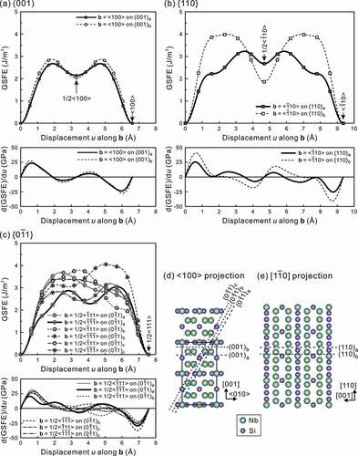
For {110}<10> slip, two glide planes ({110}a and {110}b in )) can be considered. Both the unstable stacking fault energy γusf and the theoretical shear strength τth are much lower on {110}a as summarized in , suggesting that {110}a is selected as the glide plane for <1
0> dislocations as in the case of the isostructural Mo5SiB2 [Citation17]. A < 1
0> perfect dislocation on {110}a is expected to dissociate into two collinear partial dislocations with an identical Burgers vector of 1/2 < 1
0> because of the existence of an energy minima of about 2.67 J/m2 on {110}a, and the dissociation distances are estimated to be in the range from 1.67 nm (for pure screw) to 2.16 nm (for pure edge). Of interest to note is that the stable stacking fault energy γsf is much lower on {110}b (1.86 J/m2) than on {110}a (2.67 J/m2) that is predicted to be the glide plane for <1
0> dislocations, the trend of which was similar to that evaluated for the isostructural Mo5SiB2 [Citation17]. This suggests that <1
0> dislocations may be formed on {110}b if formed as grown-in dislocations because of the lower stable stacking fault energy but that they cannot act as a dislocation source because they experience the difficulty in motion for the high resistance in both α-Nb5Si3 and Mo5SiB2.
In the case of {01}<111> slip, there are three crystallographically non-equivalent {0
1} slip planes ({0
1}a, {0
1}b and {0
1}c in )) and two non-equivalent <111> directions on each of three {0
1} planes, so that we have to consider six different cases for {0
1}<111> slip. As shown in ) and , <
> slip on {0
1}a has the lowest values for both the unstable stacking fault energy γusf and theoretical shear strength τth, which suggests that {0
1}<111> slip prefers to occur along <
> on {0
1}a. There are an energy minima at around 1/4 <
> on {0
1}a, so that a perfect 1/2 <
> dislocation dissociates into two collinear partial dislocations with an identical Burgers vector of 1/4 <
>. The dissociation distances for the coupled partial dislocations in pure screw and edge orientations are estimated to be 1.08 nm and 1.46 nm, respectively.
4. Discussion
4.1. Critical resolved shear stress
Based on the characteristics observed in stress-strain curves and deformation microstructures, we suspect that three slip systems, (001)<010> (in the [210] orientation), {110}<10> (in the [010] orientation) and {0
1}<111> (in the [001],[
10] orientations), operate in α-Nb5Si3 as in the case of Mo5SiB2. While three slip systems, {0
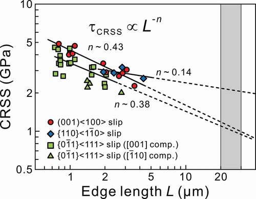
1}<111>, {100}<010> and {001}<010> were inferred to be operative in α-Nb5Si3 from trace analysis of dislocation line vectors in the TEM [Citation8], {100}<010> was not identified in the present study. The absence of the {100}<010> slip activation in the micropillar of binary α-Nb5Si3 the present study may be related partly to the difference in the chemical composition because the materials previously investigated contained Ti as a major alloying element [Citation8]. However, the detailed effects of alloying elements on the relative ease of the {100}<010> slip activation have not been clarified yet. The critical resolved shear stress (CRSS) for the three slip systems are plotted in as a function of edge length L. The CRSS values are calculated from the yield stress obtained as either the elastic limit or the stress for the first strain burst, and Schmid factors listed in . An inverse power-law scaling is applicable for each of the three slip systems as in the cases of many crystalline materials [Citation9–19,Citation33–37]. The power-law exponents n for (001)<010>, {110}<1
0> and {0
1}<111> slip are estimated to be about 0.43, 0.14 and 0.38, respectively. To be noted in is that the n values for (001)<010> and {110}<1
0> slip in α-Nb5Si3 are much higher than the corresponding values (0.18, 0.16) for Mo5SiB2 and are close to those reported for body centered cubic (bcc) metals. Although the n value for the {110}<1
0> slip in α-Nb5Si3 may contain a somewhat larger error than the other two because of the limited number of data points used for the power-law fitting, the following discussion will be conducted based on these n values.
Figure 5. Specimen size (edge length L) dependence of CRSS for (001)<100>, {110}<10> and {0
1}<111> slip. The shaded area (L = 20 − 30 μm) corresponds to the size range, where the CRSS values for micropillar specimens coincide with those obtained for bulk single crystals of many fcc and bcc metals
The size-dependent CRSS values are known to coincide with the corresponding bulk CRSS value when the specimen size is 20 − 30 μm for many face centered cubic (fcc) and bcc metals [Citation33]. Assuming the same holds true for (001)<010>, {110}<10> and {0
1}<111> slip in α-Nb5Si3, the bulk CRSS (τbulk) values at room temperature can be estimated to be 1.1 ± 0.1, 2.1 ± 0.1 and 1.0 ± 0.1 GPa, respectively. The estimated bulk CRSS values for (001)<010> and {0
1}<111> slip in α-Nb5Si3 are much lower than those (2.7 ± 0.1 and 2.1 ± 0.1 GPa) in Mo5SiB2, while that for {110}<1
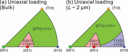
0> slip is comparable to that (1.9 ± 0.1 GPa) in Mo5SiB2. ) shows the orientation dependence of operative slip system calculated based on the estimated bulk CRSS values for (001)<010>, {110}<1
0> and {0
1}<111> slip. In contrast to Mo5SiB2, there is no orientation range where {110}<1
0> slip is expected to operate in the bulk of α-Nb5Si3, because of its relatively high bulk CRSS. {110}<1
0> slip is expected to operate in α-Nb5Si3 when the specimen size becomes smaller ()) as calculated with the CRSS values for the three slip systems at L ~ 2 μm.
Figure 6. Orientation dependence of the operative slip systems under uniaxial loading calculated with (a) the estimated bulk CRSS values and (b) those for micropillar specimens with L ~ 2 μm for the three slip systems, (001)<100>, {110}<10> and {0
1}<111> in α-Nb5Si3.
In intermetallic compounds with very complex crystal structures (such as TM5Si3-type silicides (TM: transition metal) with the D8l, D8m and D88 structures), the density of grown-in dislocations is expected to be very low (virtually zero) because the dislocation generation as well as dislocation motion are considered to be terribly difficult due to the very high self-energy of dislocations and very high frictional stress for their motion, all of which are related to the brittleness of these intermetallics. It is thus reasonable to assume that no grown-in dislocations that can act as a dislocation source are contained in micropillar specimens of α-Nb5Si3 single crystals. Consequently, the CRSS values experimentally obtained in the present study are considered to correspond to the critical shear stress required to nucleate new dislocations in the micropillar specimen, as proposed by Bei et al. [Citation38].
Following the method used by Bei et al. [Citation38], the critical shear stress τcrit required for spontaneous nucleation of new dislocations are evaluated for the following three cases; (a) a full dislocation loop formation inside the micropillar specimen, (b) a half dislocation loop formation from the side surface, and (c) a quarter dislocation loop formation from the corner of the micropillar specimens. The evaluation method for τcrit is detailed in our previous paper [Citation18]. The values of surface energy used for the evaluation are listed in . The geometry-dependent correction factor m is estimated to be 0.537 using eq. 17 in [Citation39] for the case (b) of a half dislocation loop formation, while it is assumed to be 0.3 for the case (c) of a quarter dislocation loop formation based on the discussion by Bei et al. [Citation38]. The core cut off radius is set equal to the magnitude of the Burgers vector b. The values of τcrit are estimated to be about 9.3, 5.8 ~ 6.1, 3.2 ~ 3.5 GPa for the three cases, respectively. The estimated τcrit values do not vary much with slip system because the isotropic elastic constants (G = 127.9 GPa, ν = 0.229 [Citation31]) are used for the present evaluations. The CRSS values for (001)<010>, {110}<10> and {0
1}<111> slip obtained for smaller micropillar specimens with L < ~1 μm () are in fairly good agreement with the estimated τcrit for cases (b) and (c), suggesting that the CRSS values obtained in the micropillar compression tests actually correspond to the critical shear stress for spontaneous dislocation nucleation from the surfaces or edges of micropillar specimens.
4.2. Comparison with Mo5SiB2
Although the operative slip systems in single crystalline micropillars of α-Nb5Si3 are identical to those observed in isostructural Mo5SiB2, the relative CRSS values among the three operative slip systems as well as the magnitude of the power-law exponent (n) are quite different for these two silicides, α-Nb5Si3 and Mo5SiB2. Here, we discuss possible reasons for these characteristics based on the results of the first-principles DFT calculations. The power-law exponent n is generally reported to depend on the bulk CRSS values (corresponding to the frictional stress) so that the n value decreases with the increase in the bulk CRSS for many fcc and bcc metals, in which the so-called single-arm dislocation source (SAS) model is considered to be applicable to describe the size-dependent strength. ) plots the n values for the three operative slip systems both in α-Nb5Si3 and Mo5SiB2 as a function of the bulk CRSS τbulk values estimated based on the size-dependent CRSS obtained in micropillar compression tests. There seems a clear trend that slip systems with the higher bulk CRSS values exhibit the lower n values as in the case of fcc and bcc metals, although the mechanism that governs the size-dependent CRSS in α-Nb5Si3 and Mo5SiB2 is the dislocation nucleation from the surfaces or edges of micropillar specimens as described above. The bulk CRSS values (τbulk) obtained in micropillar testing for α-Nb5Si3 and Mo5SiB2 are plotted in ) as a function of the theoretical shear strength τth evaluated as the maximum of the derivative of the GSFE curves, indicating a positive linear relationship between the two values. This is reasonable in that the stress required to nucleate new dislocations from the surfaces or edges of micropillar specimens (τbulk) depends positively on the theoretical shear strength τth. Therefore, a negative linear relationship is also found between the power-law exponent (n) and the theoretical shear strength τth, as shown in ). Nix and Lee [Citation40] proposed a surface nucleation model to describe the size dependent CRSS for micropillars that do not contain any dislocation sources. In their simplified model, the steady-state flow stress τss for micropillar specimens in a cylindrical shape with a diameter D is estimated to follow an inverse power-law relationship,. The parameter m is an exponent that characterizes the stress τ dependence of the dislocation nucleation frequency ω approximated with the following equation,
Figure 7. Relationship among the power-law exponent (n), estimated bulk CRSS (τbulk) and theoretical shear strength (τth). (a) n – τbulk, (b) τbulk – τth and (c) n – τth. Error bars for τbulk correspond to the values calculated using the fitted power-law equations for L = 20 μm (upper limit) and 30 μm (lower limit)
where ω0 is the average nucleation frequency per atomic site on the surface at the theoretical shear strength τth. Assuming that the Nix-Lee model is applicable to the present case, the negative relationship between the n value and theoretical shear strength τth shown in ) indicates that the m parameter in Equationeq. (1)(1),
(1), exhibits a tendency to increase with theoretical shear strength τth. The positive correlation between τth and m would be quite reasonable because it means that the higher the τth is, the harder the dislocation nucleation from the surface is.
To be noted is that although the estimated bulk CRSS values (1.1 ± 0.1 and 1.0 ± 0.1 GPa) for the (001)<010> and {0¯11}<111> slip in α-Nb5Si3 are much lower than those (2.7 ± 0.1 and 2.1 ± 0.1 GPa) for Mo5SiB2, instantaneous failure occurs rather easily in α-Nb5Si3, as can be recognized from the unsuccessful trials of the interruption of compression tests for the [010] and [110]-oriented micropillar specimens before the failure occurred (), which is in marked contrast to the case of Mo5SiB2 [Citation17]. This is believed to be due to the lower fracture toughness value for α-Nb5Si3, as also predicted from the lower surface energies for α-Nb5Si3 (2.5 ~ 2.6) than for Mo5SiB2 (2.8 ~ 3.1) () by first-principles DFT calculations. Unfortunately, these characteristics may indicate that α-Nb5Si3 possesses an inherent disadvantage over Mo5SiB2 as a strengthening phase in refractory metal (Mo or Nb)-based alloys. However, we believe that improvement of the inherent brittleness of α-Nb5Si, for example, by adding alloying elements would be highly possible so as to utilize α-Nb5Si3 as a strengthening phase in refractory metal-based alloys.
5. Conclusions
Micropillar compression tests of α-Nb5Si3 single crystals with four different loading axis orientations of [021], [010], [001] and [10] were conducted at room temperature as a function of specimen size. The results obtained are summarized as follows.
Three slip systems, (001)<010>, {110}<1
0> and {0
The CRSS values for (001)<010>, {110}<1
The value of fracture toughness by single-cantilever bend testing of a micro-beam specimen with a chevron notch parallel to (001) is 1.79 MPa m1/2, which is considerably lower than that (2.43 MPa m1/2) reported for isostructural Mo5SiB2.
Disclosure statement
No potential conflict of interest was reported by the authors.
Additional information
Funding
References
- Zhao JC, Westbrook JH. Ultrahigh-temperature materials for jet engines. MRS Bull. 2003;28:622–627.
- Perepezko JH. The hotter the engine, the better. Science. 2009;326:1068–1069.
- Subramanian PR, Mendiratta MG, Dimiduk DM. The development of Nb-based advanced interemetallic alloys for structural applications. JOM. 1996;48:33–38.
- Jackson MR, Bewlay BP, Rowe RG, et al. High-temperature refractory metal-intermetallic composites. JOM. 1996;48:39–44.
- Bewlay BP, Jackson MR, Zhao JC, et al. A review of very-high-temperature Nb-silicide-based composites. Metall Mater Trans. 2003;34A:2043–2052.
- Tsakiropoulos P. On Nb silicide based alloys: alloy design and selection. Materials. 2018;11:844.
- Villars P, Calvert L, editors Pearson’s handbook of crystallographic data for intermetallic phases. Vol. 2. Materials Park (OH): American Society for Metals; 1985.
- Sekido N, Miura S, Yamabe-Mitarai Y, et al. Dislocation character and operative slip systems in α-Nb5Si3 tested at 1673 K. Intermetallics. 2010;18:841–845.
- Inoue A, Kishida K, Inui H, et al. Compression of micro-pillars of a long period stacking ordered phases in the Mg-Zn-Y systems. MRS Symp Proc. 2013;1516:151–156.
- Okamoto NL, Kashioka D, Inomoto M, et al. Compression deformability of Γ and ζ Fe-Zn intermetallics to mitigate detachment of brittle intermetallic coating of galvannealed steels. Scripta Mater. 2013;69:307–310.
- Okamoto NL, Inomoto M, Adachi H, et al. Micropillar compression deformation of single crystals of the intermetallic compound ζ-FeZn13. Acta Mater. 2014;65:229–239.
- Nakatsuka S, Kishida K, Inui H. Micropillar compression of MoSi2 single crystals. MRS Symp Proc. 2015;1760:mrsf14-1760-yy05-09.
- Okamoto NL, Fujimoto S, Kambara Y, et al. Size effect, critical resolved shear stress, stacking fault energy, and solid solution strengthening in the CrFeMnCoNi high-entropy alloy. Sci Rep. 2016;6:35863.
- Chen ZMT, Okamoto NL, Demura M, et al. Micropillar compression deformation of single crystals of Co3(Al,W) with the L12 structure. Scripta Mater. 2016;121:28–31.
- Zhang J, Kishida K, Inui H. Specimen size and shape dependent yield strength in micropillar compression deformation of Mo single crystals. Int J Plast. 2017;92:45–56.
- Higashi M, Momono S, Kishida K, et al. Anisotropic plastic deformation of single crystals of the MAX phase compound Ti3SiC2 investigated by micropillar compression. Acta Mater. 2018;161:161–170.
- Kishida K, Maruyama T, Matsunoshita H, et al. Micropillar compression deformation of single crystals of Mo5SiB2 with the tetragonal D8l structure. Acta Mater. 2018;159:416–428.
- Kishida K, Shinkai Y, Inui H. Room temperature deformation of 6H-SiC single crystals investigated by micropillar compression. Acta Mater. 2020;187:19–28.
- Kishida K, Kim J, Nagae T, et al. Experimental evaluation of critical resolved shear stress for the first-order pyramidal c + a slip in commercially pure Ti by micropillar compression method. Acta Mater. 2020;196:168–174.
- Deng X, Bitler J, Chawla KK, et al. Toughness measurement of cemented carbides with chevron-notched three-point bend test. Adv Eng Mater. 2010;12:948–952.
- Mueller MG, Pejchal V, Žagar G, et al. Fracture toughness testing of nanocrystalline alumina and fused quartz using chevron-notched microbeams. Acta Mater. 2015;86:385–395.
- Vitek V. Intrinsic stacking faults in body-centered cubic crystals. Philos Mag. 1968;18:773–786.
- Vitek V, Paidar V. Chapter 87, Non-planar dislocation cores: a ubiquitous phenomenon affecting mechanical properties of crystalline materials. In: Hirth JP, editor. Dislocations in solids. Vol. 14. Amsterdam (Netherlands): Elsevier; 2008. p. 439–514.
- Kresse G, Furthmüller J. Efficient iterative schemes for ab initio total-energy calculations using a plane-wave basis set. Phys Rev B. 1996;54:11169–11186.
- Perdew JP, Burke K, Ernzerhof M. Generalized gradient approximation made simple. Phys Rev Lett. 1996;77:3865–3868.
- Monkhorst HJ, Pack JD. Special points for Brillouin-zone integrations. Phys Rev B. 1976;13:5188–5192.
- Dimiduk DM, Woodward C, LeSar R, et al. Scale-free intermittent flow in crystal plasticity. Science. 2006;312:1188–1190.
- Devincre B, Kubin L. Scale transitions in crystal plasticity by dislocation dynamics simulations. C R Physique. 2010;11:274–284.
- Jaya BN, Kirchlechner C, Dehm G. Can microscale fracture tests provide reliable fracture toughness values? A case study in silicon. J Mater Res. 2015;30:686–698.
- Mendiratta MG, Lewandowski JJ, Dimiduk DM. Strength and ductile-phase toughening in the two-phase Nb/Nb5Si3 alloys. Metall Trans A. 1991;22A:1573–1583.
- Chen Y, Hammerschmidt T, Pettifor DG, et al. Influence of vibrational entropy on structural stability of Nb-Si and Mo-Si systems at elevated temperatures. Acta Mater. 2009;57:2657–2664.
- Hirth JP, Lothe J. Theory of dislocations. 2nd ed. New York: John Wiley & Sons; 1982.
- Dimiduk DM, Uchic MD, Parthasarathy TA. Size-affected single-slip behavior of pure nickel microcrystals. Acta Mater. 2005;53:4065–4077.
- Schneider AS, Kaufmann D, Clark BG, et al. Correlation between critical temperature and strength of small-scale bcc pillars. Phys Rev Lett. 2009;103:105501.
- Uchic MD, Shade PA, Dimiduk DM. Plasticity of micrometer-scale single crystals in compression. Annu Rev Mater Res. 2009;39:161–186.
- Korte S, Clegg WJ. Discussion of the dependence of the effect of size on the yield stress in hard materials studied by microcompression of MgO. Philos Mag. 2011;91:1150–1162.
- Lee SW, Nix WD. Size dependence of the yield strength of fcc and bcc metallic micropillars with diameters of a few micrometers. Philos Mag. 2012;92:1238–1260.
- Bei H, Gao YF, Shim S, et al. Strength differences arising from homogeneous versus heterogeneous dislocation nucleation. Phys Rev B. 2008;77:060103.
- Beltz GE, Freund LB. On the nucleation of dislocations at a crystal surface. Phys Stat Sol (B). 1993;180:303–313.
- Nix WD, Lee SW. Micro-pillar plasticity controlled by dislocation nucleation at surfaces. Philos Mag. 2011;91:1084–1096.
- Ito K, Ihara K, Tanaka K, et al. Physical and mechanical properties of single crystals of the T2 phase in the Mo-Si-B system. Intermetallics. 2001;9:591–602.
Appendix.
The fracture toughness, KIC was evaluated from the result of a single cantilever bend test for a chevron-notched micro-beam specimen with dimensions of l = 12 μm, W = 4.5 μm and B = 3 μm, and notch lengths a0 and a1, and a crack length a () using the following equation [Citation20,Citation21]).
where Pmax is the maximum load reached during the bend test. YC(α0, α1) is the dimensionless geometrical factor that can be calculated with the following equation.
where CV(α) is compliance of the specimen, α0 = a0/W, α1 = a1/W, α = a/W, αC = aC/W, and aC is a critical crack length (). For the calculation of YC(α0, α1), the method proposed by Deng et al. [Citation20] was applied. Please refer to [Citation20] for the details.
Figure A1. Schematic illustration of (a) a chevron-notched micro-beam specimen for single cantilever bend test and (b) the shape of a chevron-notch