
ABSTRACT
The purpose of this study was to clarify how elite artistic (synchronised) swimmers generate fluid forces with their hands during two kinds of sculling motions: flat sculling in the back-layout position and support sculling in the vertical position. We used the pressure-distribution measuring method to estimate unsteady fluid forces acting on the hand during sculling motions performed by seven elite artistic swimmers. In addition, we simultaneously analysed sculling motions using three dimensional-direct linear transformation methods. We found that sculling motions continuously generated fluid forces that are large during the stroke phase and small during the transition phase. Lift force was efficiently generated, and a large upward propulsive force was obtained during the stroke phase in both flat and support sculling. During the outside transition from out- to in-sculling, the net vertical load (= gravitational force—buoyant force) was supported by the drag force. In both flat and support sculling, artistic swimmers generated an even fluid force in the upward direction during the in-sculling and out-sculling phases to maintain a stable position.
Introduction
In artistic swimming, which is also known as ‘synchronised swimming’, flat sculling is used to maintain a horizontal position and support sculling is used to maintain vertical positions. Homma (Citation2017) reported net vertical load (= gravitational force—buoyant force) values for eight female artistic swimmers with an average weight of 52.7 ± 4.40 kg: 7.77 ± 0.95 kgf at the highest ballet-leg position, in which one leg is raised above water in the back-layout position and 12.95 ± 1.72 kgf at the highest ballet-leg double position, in which both legs are raised above the water. Based on these results, it is clear that sculling is needed to maintain body position and provide an upward propulsive force to balance the net vertical load. Sculling is an important technique used not only for supporting and maintaining balance for body positions (Nesbitt, Citation1991), but also for propulsion, changing direction, and rotation (Forbes, Citation1989; Homma & Homma, Citation2006; Lundholm & Ruggieri, Citation1976). Thus, it is an indispensable technique for artistic swimming.
Several kinematic studies have investigated various sculling techniques, most of which have focused on motion analysis (Francis & Smith, Citation1982, Citation1983; Gomes et al., Citation2014; Hall, Citation1985, Citation1996; Homma & Homma, Citation2005, Citation2006; Homma, Homma, & Washizu, Citation2008; Rutkowska-Kucharska & Wuchowicz, Citation2016; Rybuyakova, Lesgaft, & Pybyakova, Citation1991; Zinzen, Antonis, Cabri, Serneels, & Clarys, Citation1992). In particular, for flat sculling, Homma and Homma (Citation2005) analysed flat sculling techniques used by ten elite artistic swimmers employing a three dimensional-direct linear transformation (3D-DLT) method. Sculling techniques for more advanced artistic swimmers included holding the elbows and upper arms stationary and changing the attack angles of the hands smoothly and evenly. Motion characteristics of flat sculling include spreading elbows to the outside, combining forearms and hands into a single unit, and using horizontal motions during sculling. The trajectory of the hands during sculling do not transverse a figure eight, as described in most training conventions. Instead the hand trace a droplet-shaped figure with the inside tapered.
Homma and Homma (Citation2006) analysed support sculling movements performed by 10 world-ranked artistic swimmers using the 3D-DLT method. During support sculling, swimmers kept their elbows and upper arms stationary and their forearms horizontal. Palms faced downwards throughout the sculling motion and the attack angle of the hands was maintained to produce an effective vertically upward force.
Characteristics of elite artistic swimmers’ motions during flat and support sculling are reported in previous kinematic studies. Sculling motions produce propulsive forces by imparting momentum to water or any other medium, thus generating various fluid forces. Analysis of sculling therefore requires measurement of fluid force generated by the hands. A few studies are available on fluid forces generated during sculling motions (Diogo et al., Citation2010; Gomes et al., Citation2019; Gomes, Tremea, Silveira, de Souza Castro, & Loss, Citation2011; Homma, Kawai, & Takagi, Citation2016; Kamata, Miwa, Matsuuchi, Shintani, & Nomura, Citation2006; Lauer, Rouard, & Vilas-Boas, Citation2016; Takagi et al., Citation2014). Gomes et al. (Citation2011) analysed the effective propulsive force produced one swimmer when sculling in a vertical position with head above the water’s surface. Each cycle was divided into four phases: in-sweep, transition from in-sweep to out-sweep, out-sweep and transition from out-sweep to in-sweep. Force was almost constant across all phases (approximately 9.5 N). Takagi et al. (Citation2014) investigated how unsteady forces are generated during sculling by a competitive swimmer using particle image velocimetry (PIV) to acquire data on the kinematics. They found that a skilled swimmer produces large unsteady fluid forces when a leading-edge vortex forms on the dorsal side of the hand and wake capture occurs on the palm side. Homma et al. (Citation2016) analysed hydrodynamic forces acting on the hand during flat sculling and support sculling by one elite artistic swimmer. Their results were consistent with the findings of Takagi et al. (Citation2014). However, in the above reports, a single participant was studied or the participant was not an artistic swimmer. How elite artistic swimmers generate fluid forces by hand during sculling remains unclear.
To estimate the fluid forces, a pressure-distribution method recently became available for underwater measurements. This method directly measures pressure distributions on hands of swimmers using small pressure sensors. The method enables estimation of forces generated in a fluid under variable conditions, such as those produced during sculling. Momentum vectors and acceleration constantly change during sculling (Kudo, Yanai, Wilson, Takagi, & Vennell, Citation2008; Takagi & Sanders, Citation2002; Takagi & Wilson, Citation1999). Since the experimental procedure involves only equipping the hand with a sensor for making periodic measurements, the method can be easily used during training. The effectiveness of the method for evaluating propulsion techniques has been demonstrated in previous studies (Takagi et al., Citation2014; Tsunokawa, Takagi, Sengoku, & Tsubakimoto, Citation2012). The above information suggests that valuable information on effective sculling motions can be obtained by estimating fluid forces generated on swimmers’ hands during sculling using the pressure-distribution measuring method. Characteristics of propulsive force generated by elite artistic swimmers, including magnitude and direction, has not been investigated.
The objective of this study was to estimate unsteady fluid forces on the hands during sculling motions (flat and support) using pressure-distribution measurements and to clarify characteristics of propulsive force generated by elite artistic swimmers, including magnitude and direction, has not been investigated. We hypothesise that elite artistic swimmers generate vertical upward fluid forces continually to support their net vertical load in both sculling motions. Data that emerges from this study are expected to become useful for all athletes and coaches involved the artistic swimming to enhance swimmer performance.
Materials and methods
Participants
Participants in this study were seven elite female artistic swimmers. Participants were all proficient swimmers who were members of the Japanese National Team; five participated in the London Olympics in 2012 or the Rio de Janeiro Olympics in 2016 or both, and the other two competed in the World Swimming Championships in 2013 (). This study was conducted with approval from the Research Ethics Committee of the Faculty of Sports, University of Tsukuba and Health Sciences and following the Helsinki Declaration. Participation in the experiment was agreed to by each swimmer after the purpose and the method of this study were fully explained.
Table 1. Characteristics of participants.
Experiment
Flat sculling in the stationary back-layout position and support sculling in the stationary vertical position () were each performed for 5 s. Participants were instructed to maintain the same body height as much as possible during both sculling motions.
Figure 1. Flat sculling in the back-layout position (left) and support sculling in the vertical position (right).
Sculling motions were monitored using four video cameras (), which were set with a shutter speed of 1/500 s and a sampling frequency of 60 Hz. A calibration tool (1.6 m × 1.82 m × 1.3 m) and 168 control points were used to reconstruct 3D coordinate space by the DLT algorithm. A fixed coordinate system (x-y-z) corresponded to the calibration tool. In the longitudinal direction while participants were performing the trials, left and right were considered the x-axis, front and rear the y-axis, and up and down the z-axis. The errors that occurred during recreation of calibrated coordinates were 0.0028 m (x-axis), 0.0038 m (y-axis) and 0.0047 m (z-axis). Light-emitting diode (LED) markers were placed at three points on the participants: 1) lateral aspect of the left wrist, 2) medial aspect of the left elbow and 3) the left acromion. Marking points on the left hand were the tips of the first, third and fifth fingers. Four video cameras were synchronised using an LED lamp (PH-110, DKH, Japan) in the view-angle of each video camera. To synchronise the video cameras with pressure data, the LED lamp in the view of the video cameras and the electric signal to flash the LED lamp were used as triggers. A switch that generated an electric signal was used to flash the LED lamp. The same electric signal was fed to the sensor interface, which initiated recording via the pressure sensor.
Figure 2. Experimental apparatus and a layout of cameras.
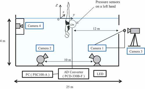
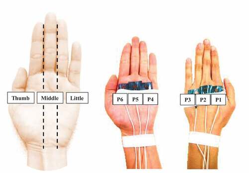
Small waterproof pressure sensors (PS.05KC, Kyowa, Japan) were attached to six points on each participant’s left hand to measure pressure distributions during sculling motions. Before the experiments, all pressure sensors were carefully calibrated based on a relationship between water depth and hydrostatic pressure (mean error: 2.3%). Using previous studies (Ozaki, Matsuuchi, Takagi, & Nakashima, Citation2008; Ozaki, Takagi, Nakashima, & Matsuuchi, Citation2009), pressure sensors were attached to three areas of the hand: thumb, and middle and little fingers, as shown in , on both the palm and the dorsum. On the dorsum, sensors were attached around the metacarpophalangeal joints of the second, third and fourth fingers, and the sensors on the palm corresponded with those on the dorsum (). The hand was sectioned into the following three longitudinal areas: thumb, from the first finger to the border of the second and third fingers; middle, from the border of the second and third fingers to the border of the third and fourth fingers; and little, from the border of the third and fourth finger to the fifth finger. A pressure sensor was attached to each area on the palm and the dorsum of the hand using acrylic air-tight waterproof tape and vinyl tape. Signals from pressure sensors were collected by data acquisition software (DCS-100A, Kyowa, Japan) via a sensor interface (PCD-330B-F, Kyowa, Japan), and were recorded on a personal computer with a sampling frequency of 200 Hz.
Figure 3. The hand area which is divided into three and the attachment position of the six pressure sensors on the palm side and the dorsal side.
Definition of sculling phase
As previously defined (Homma & Homma, Citation2005, Citation2006), the outermost position (from the body) was defined as Out and the innermost position as In. The phase from In to Out was defined as the out-sculling phase and the phase from Out to In as the in-sculling phase. Sculling comprised two phases. The elbow angle in the x-y plane was used for flat sculling and the pronation/supination angle of the forearm in the x-y plane for support sculling to distinguish these phases. The elbow angle was defined as an angle between a line joining the acromion, medial aspect of the elbow and medial aspect of the wrist. The definition of each phase was as follows:
Out-sculling phase: The phase from the minimum value (In) of the elbow angle and the pronation/supination angle of the forearm to the maximum value of these two angles.
In-sculling phase: The phase from the maximum value (Out) of the elbow joint angle and the pronation/supination angle of the forearm to the minimum value of the two angles.
Data analysis
A sculling cycle starts at the In position with the hand placed the closest to the centre of the body. One cycle, which was the most stable motion from three cycles in the middle part of each trial, was analysed. Numerical analysis software (MATLAB, MathWorks, USA) was used to interpolate the pressure data to 60 Hz using spline interpolation. Pressure values and actual coordinate values were smoothed using a low-pass Butterworth digital filter with a cut-off frequency at 6 Hz (Tsunokawa et al., Citation2012). Each marking point on the body recorded in the images was manually digitised using the motion-analysis software (Frame DIAS IV, DKH, Japan), and actual coordinates on the fixed-axis system were calculated using the 3D-DLT method.
We assumed that the thickness of the palm and the dorsum of the hand was small. In addition, the dynamic pressure on the hand due to sculling was estimated by first subtracting the pressure on the dorsum of the hand from that on the palm and then eliminating the effect of static pressure at the location of the pressure sensor. The measured pressure value for each area was taken as a representative value. The fluid force on each area was calculated by multiplying the calculated dynamic pressure by the projected area. The projected area of the three areas constituting the hand was calculated by a quadrature method through visual observation, with the hand forms described on grid paper with 1 mm intervals. The sum of fluid forces in the three areas was defined as the fluid force on the entire hand (Fhand). The reliability of Fhand measured by pressure distribution has been reported in previous studies (Takagi & Wilson, Citation1999).
Definitions and calculations of kinematic parameters and directions of fluid forces
Marking points on the hand were labelled as points M1 (third fingertip), M2 (first fingertip) and M3 (fifth fingertip) and are shown in ). We assumed that the midpoint between M2 and M3 was the centre of the hand. The midpoint between M2 and M3 was defined as point C, and the velocity of the hand (VH) was obtained by taking the derivative of the displacement at point C.
Figure 4. Definitions of the local coordinate system on a hand (a) and a definition of the angle of attack, various components of the fore (b).
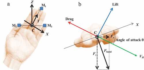
The fluid-force vector and the hand-attachment angle were calculated from actual coordinate values obtained via motion analysis; thus, a moving axis system H (X-Y-Z) originating from point C was defined ()). When defining this system, the Y-axis was set along the line connecting point C and point M1, and the Z-axis was set to be perpendicular to the line joining C to M1, and C to M2. The X-axis was set perpendicular to both Z and Y. Here, VH is defined as the velocity vector and was transformed into the moved axis system H.
The attack angle θ was defined as the angle of VH with respect to the X-Y plane. In addition, since the estimated fluid force acted perpendicularly on the hand, it was assumed that the direction of vector Z and the fluid force crossed at point C. Consequently, the direction of the fluid force was determined based on vector Z, and the fluid-force vector acting on the hand was calculated (Fhand). However, since not all fluid forces on the hand acted as propulsive forces during sculling, it was necessary to consider the direction in which the fluid force was applied. Thus, a unit vector was obtained from vector Z, and the fluid-force vector on the hand was divided into the three directions (x, y and z). Force in the direction of the swimmer’s propulsion [or the perpendicular direction (z-axis)] was denoted by Fz and defined as the upward propulsive force. Moreover, the forces on the x- and y-axes were denoted as Fx and Fy, respectively ()). The force which acts in a direction perpendicular to VH was defined as lift and the force which acts in a direction opposite to the VH was defined as drag.
Analysis items
The analysis items were:
Fhand: sum of fluid forces acting on the entire hand (N). Fhand is measured without considering direction, and it assumes a positive value when the palm generates fluid force on the water.
Fx, y, z: fluid force in each direction (N). Fz is the fluid force generated by the palm in the direction of propulsion; it assumes a negative value when the swimmer pushes water vertically downward and generates upward fluid force.
P1- 6: pressure measured by each sensor (N/m2).
Sculling velocity: composite velocity of the hand (m/s).
Sculling time: time required for sculling (s).
Angle of attack: the angle of the hand with respect to the velocity vector (deg).
Sculling pattern: orbit of the hand on the x-z plane.
Mean values of the kinematic and kinetic variables were calculated. Data comparison between Out-sculling and In-sculling in each sculling technique within the participants was conducted by using paired t-tests, and the significance level was set at p < 0.05.
Results
Motion analysis of the upper limb
Sculling time, velocity and angle of attack in flat and support sculling are shown in . The sculling time during the out-sculling phase was significantly longer than that during the in-sculling phase in both sculling techniques. Moreover, the velocity during the in-sculling phase was significantly higher than during the out-sculling phase.
Table 2. Sculling time, velocity and attack angle for flat sculling and support sculling.
As a typical example, a) the temporal change in the sculling velocity, b) the angle of attack during one cycle and c) the sculling pattern of the cycle during the two kinds of sculling (flat sculling in swimmer G and support sculling in swimmer C) are shown in , respectively.
Figure 5. Changes in hand moving velocity (a), angle of attack (b), movement locus of the origin of a hand (c), resultant force: Fhand (d) and three-direction component of force: Fx, y, z (e) during flat sculling for swimmer G.
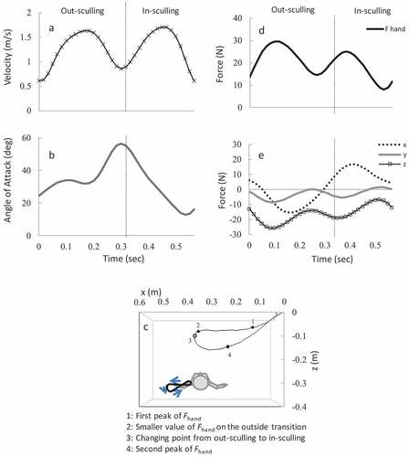
Figure 6. Changes in hand moving velocity (a), angle of attack (b), movement locus of the origin of a hand (c), resultant force: Fhand (d) and three-direction component of force: Fx,y,z (e) during support sculling for swimmer C.
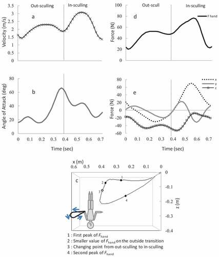
For all swimmers in both sculling modes, sculling-velocity peaked during strokes showing a curve with bimodal characteristics (See ). The angle of attack increased from the start of the sculling until the stroke of the out-sculling phase. The mean angle of attack during the stroke was 33.8 ± 2.07° for flat sculling and 27.2 ± 4.11° for support sculling. Later, the angle gradually increased during the outward transition which is a switching phase from out- to in-sculling phase, assuming a maximum value of 60–70° for both sculling modes. The angle then gradually decreased during the inward transition which is a switching phase from in- to out-sculling phase, and assumed a minimum value of 1–17º for flat sculling and 0–14º for support sculling (See ).
Flat sculling showed a drop-shaped pattern with a sharp corner inside. Patterns exhibited higher In (closer to the surface) and lower Out. The hand moved almost horizontally during the stroke for the out-sculling phase; it moved towards the bottom of the pool during the outward transition (See ). For support sculling, all swimmers except one exhibited elliptical patterns with a shaper corner inside, and their hands moved almost horizontally after they switched the direction of the hands in front of their body and during the out-sculling phase (See ).
Fluid force acting on the hand
shows maximum, minimum and mean fluid force, mean impulse on the entire hand (Fhand), and fluid force in the propulsion direction (Fz) during flat and support sculling. As a typical example, d) the temporal change in the resultant fluid force (Fhand) and e) three-direction component of force (Fx,y,z) in flat and support sculling are shown in , respectively.
Table 3. The maximum, minimum, mean, and impulse of Fhand and Fz for flat sculling and support sculling.
Fhand in both sculling modes peaked during the out-sculling phase and in-sculling phase (See ), and Fhand was less during transitions which is a switching phase either from in- to out-sculling or from out- to in-sculling phases. A curve with bimodal characteristics was seen for all swimmers. For flat sculling, no significant difference was observed in maximum and mean Fhand between the in-sculling and out-sculling phases; however, a significant difference for minimum Fhand and impulse Fhand was found between in-sculling and out-sculling phases. As with Fhand, a significant difference for minimum Fz and impulse Fz was found between in-sculling and out-sculling phases, but no significant differences were found for maximum and mean Fz. For support sculling, maximum F hand during the in-sculling phase was significantly higher than that during the out-sculling phase by approximately 25 N.
Discussion and implications
In competitive swimming, a swimming stroke has phases that generate propulsive force and phases that do not (Maglischo, Citation2003). Nevertheless, this study shows that sculling motions continuously provide vertically upward fluid force (Fz), and all phases are propulsive. This result is consistent reports from Francis and Smith (Citation1982, Citation1983) and Homma et al. (Citation2016).
The fluid force waveform (Fhand) in both sculling motions showed a curve with bimodal characteristics. This finding implies that the stroke phase produces the larger propulsive force and the transition phase generates less propulsive force. This result is consistent with reports from Takagi et al. (Citation2014) and Gomes, Boeira, and Fagundes (Citation2017). During a stroke in which fluid force peaks, the sculling velocity peaks almost simultaneously, and the angle of attack at that moment is 20–50°. Schleihauf (Citation1979) studied lift generation by propulsive force under steady conditions via a wind-tunnel experiment using a hand model and showed that an angle of attack of approximately 40º maximises the lift component. Zielinski (Citation2005) reported that elite synchronised swimmers displayed angles of attack of 20–50º. The above findings suggest that swimmers in this study effectively generated the lift during a stroke. Swimmers showed an angle of attack of 60–70° during the outward transition and sculled downward, and they likely supported the net vertical load by using drag forces during the transition from out- to in-sculling. These results are again consistent with previous studies (Francis & Smith, Citation1982, Citation1983; Homma & Homma, Citation2005, Citation2006; Homma et al., Citation2008). These studies indicated that the horizontal stroke significantly contributes to lift and generates a propulsive force with a large drag component in during outward transition. The trajectory of the hands during sculling was clarified and did not transverse a figure eight, as described in several manuals for coaches and swimmers (DeNegri & McGowan, Citation2005; Lundholm & Ruggieri, Citation1976; Rybuyakova et al., Citation1991; Yates & Anderson, Citation1958; Zielinski, Citation2001, Citation2005). Rather, hands traced a droplet-shaped figure with the inside tapered.
As expected, the fluid force and the impulse of the out-sculling phase and the in-sculling phase were similar in flat sculling. We did not expect the same result for support sculling. Support sculling is a technique unique to artistic swimming because it involves external and internal rotations of the shoulders in addition to supination and pronation of the forearms. Homma and Homma (Citation2006) and Homma et al. (Citation2008) reported that when artistic swimmers executed support sculling techniques their shoulders are rotated external and forearms are kept in supination to maintain a constant angle of attack during the out-sculling phase. When in-sculling, the shoulders are rotated internal and the forearms are kept in pronation to maintain an optimal angle of attack, and the arms are then bought back to the front of the body. Moreover, they scull in the shape of a quarter in the range from the centre of the front of the body, where the arms can be easily moved, to the side of the body. In general, the range of motion of the radioulnar joints in the supination of the forearms with the palm facing inside at 0°, is approximately 80–90° (Thompson & Floyd, Citation2002). For this reason, support sculling, which is performed the palms facing towards the head, is an unusual because it is accomplished at almost the maximum range of motion of supination of the forearms. This finding shows that the out-sculling phase, in which the arms move from the front of the body to the side, is an anatomically difficult motion that does not effectively activate muscles, but posture is easier to maintain because the arms are opened to the left and right, coming to the side of the body. These findings suggest that even though the out-sculling phase cannot attain a high velocity because of the difficulty of the motion, it stabilises the position and lengthens sculling time, thereby producing equivalent fluid force and impulse to those produced during the in-sculling phase. This result corroborates the statement in the Star Program Manual by Synchro Canada (Citation2002), the most representative instruction manual in artistic swimming that indicates that the forces in the out-sculling and in-sculling phases are the same.
Furthermore, in both flat and support sculling, the smaller fluctuation of Fz value over one cycle can contribute to the stability of the body. As clarified in this study, even top athletes in the world cannot maintain to produce the steady Fz over one cycle. Therefore, it is important to minimise the fluctuation of Fz as much as possible. Arellano, de la Fuente, and Domínguez (Citation2009) analysed sculling propulsive arm actions in a horizontal position and concluded that the sculling propulsive action helped body displacement in the inward-, transition(supination)-, outward-phase, while the other transition (pronation) phase had a reduced contribution. Our findings that Fz decreases during transitions is consistent with Arellano’s results. We, therefore, suggest that it is important to keep the propulsive force continuously by shifting smoothly at the transition phases, i.e. a pronation and supination action of the forearm.
There were some limitations that must be considered while interpreting study results. The sample size was not sufficient for statistical analysis because participants were limited to top ranked swimmers. Only left hand data were analysed regardless of the participants’ dominant hand. In the further study we should investigate fluid forces generated by both right and left hand and increase the number of participants.
Conclusion
In this study, we used a pressure-distribution measuring method to estimate unsteady fluid forces acting on the hand during sculling motions performed by elite artistic swimmers. We found that sculling motions continually generate vertical upward fluid forces, which are larger during a stroke and smaller during transitions, as we hypothesised. Moreover, sculling motions produced equivalent vertical impulse forces during the out-sculling and in-sculling phases; these forces help swimmers maintain a stable position. In both flat and support scullings, it is recommended to move their hands horizontally during out-sculling and to feel the water pressures by the hands continuously throughout sculling. Additionally, for generating well-balanced impulse force during the out-sculling and in-sculling phases for support sculling with a large vertical net load, swimmers need advanced sculling techniques that involve forearm extra-supination and external rotation of the shoulder.
Acknowledgments
This work was supported in part by the Faculty of Health and Sport Sciences, University of Tsukuba. We are pleased to acknowledge the considerable to Dr. Takaaki Tsunokawa.
Disclosure statement
No potential conflict of interest was reported by the author(s).
References
- Arellano, R., de la Fuente, B., & Domínguez, R. (2009). A study of sculling swimming propulsive phases and their relationship with hip velocity. In A. Harrison, R. Anderson, & I. Kenny (Eds.), Scientific proceedings of the 27th international conference on biomechanics in sports (pp. 353–355). Limerick: University of Limerick.
- DeNegri, L. V., & McGowan, J. (2005). Understanding sculling mechanics. In FINA (Ed.), Synchronised swimming coaches manual, summary of presentations from previous world synchronised swimming seminars (pp. 5–9). Moscow, Russia.
- Diogo, V., Soares, S., Tourino, C., Abraldes, J. A., Ferragut, F., Morouço, P., … Fernandes, R. J. (2010). Tethered force production in standard and contra-standard sculling in synchronized swimming. In P.-L. Kjendlie, R. K. Stallman, & J. Cabri (Eds.), xith international symposium for biomechanics & medicine in swimming (pp. 67–69). Oslo: Norwegian School of Sport Science.
- Forbes, M. S. (1989). Coaching synchronized swimming effectively (2nd ed., pp. 22–24, 80–82). Champaign, IL: Leisure Press.
- Francis, P. R., & Smith, K. W. (1983). A preliminary investigation of the support scull in synchronized swimming using a video motion analysis system. In J. Terauds (Ed.), Biomechanics in sports: proceedings of the 1st International Symposium on Biomechanics in Sports (pp. 401–407). Del Mar, Calif: Research Centre for Sports: Academic Publishers.
- Francis, P. R., & Smith, K. W. (1982, June). A preliminary investigation of the support scull using video motion analysis. Synchro, pp. 17–19.
- Gomes, L. E., Boeira, L., & Fagundes, L. J. (2017). The suitability of Sanders’ model for calculation of the propulsive force generated by the hands during sculling motion. Journal of Sports Sciences, 35, 936–944. doi:10.1080/02640414.2016.1206207
- Gomes, L. E., Diogo, V., Castro, F. A. S., Vilas-Boas, J. P., Fernandes, R. J., & Figueiredo, P. (2019). Biomechanical analyses of synchronised swimming standard and contra-standard sculling. Sports Biomechanics, 18, 354–365. doi:10.1080/14763141.2017.1409258
- Gomes, L. E., Melo, M. D. O., Tremea, V. W., Torre, M. L., Silva, Y. O. D., Castro, F. D. S., & Loss, J. F. (2014). Position of arm and forearm, and elbow flexion during performance of the sculling technique: Technical recommendation versus actual performance. Motriz: Revista De Educação Física, 20, 33–41. doi:10.1590/S1980-65742014000100005
- Gomes, L. E., Tremea, V. W., Silveira, R. P., de Souza Castro, F. A., & Loss, J. F. (2011). Effective propulsive force during a support scull – A case study. Revista Mackenzie De Educacao Fisica E Esporte, 10, 28–37.
- Hall, B. (1985, October). The mechanics of sculling. Synchro, pp. 14–17.
- Hall, S. J. (1996). Support scull kinematics in elite synchronized swimmers. Paper presented at the 13th International Symposium on Biomechanics in Sports, Ontario, Canada in 1995, July (pp. 44–47). Academic Publishers, Thunder Bay, Ont.: Lakehead University.
- Homma, M., & Homma, M. (2005). Sculling techniques in synchronized swimming. In Q. Wang (Ed.), Proceedings of XXIII international symposium on biomechanics in sports (Vol. 2, pp. 932–935). Beijing: International Society of Biomechanics in Sports.
- Homma, M., & Homma, M. (2006). Support scull techniques of elite synchronized swimmers. In J. P. Vilas-Boas, F. Alves, & A. Marques (Eds.), Biomechanics and medicine in swimming X (pp. 220–223). Porto, Portugal: University of Porto.
- Homma, M., Homma, M., & Washizu, K. (2008). How do synchronized swimmers keep their legs above water surface? In T. Nomura & B. E. Ungerechts (Eds.), The book of proceedings of the 1st international scientific conference of aquatic space activities (pp. 110–115). Tsukuba: University of Tsukuba.
- Homma, M. (2017). The relationship between buoyancy and airborne weight in synchronized swimmers. Japanese Journal of Sciences in Swimming and Water Exercise, 20, 10–18. 2017-12. doi:10.2479/swex.20.10
- Homma, M., Kawai, Y., & Takagi, H. (2016). Estimating hydrodynamic forces acting on the hand during sculling in synchronized swimming. In34th International Conference on Biomechanics in Sports (pp. 1–4). Tsukuba, Japan: University of Tsukuba.
- Kamata, E., Miwa, T., Matsuuchi, K., Shintani, H., & Nomura, T. (2006). Analysis of Sculling propulsion mechanism using two-components particle image velocimetry. In J. P. Vilas-Boas, F. Alves, & A. Marques (Eds.), Biomechanics and medicine in swimming X (pp. 50–52). Porto: University of Porto.
- Kudo, S., Yanai, T., Wilson, B., Takagi, H., & Vennell, R. (2008). Prediction of fluid forces acting on a hand model in unsteady flow conditions. Journal of Biomechanics, 41, 1131–1136. doi:10.1016/j.jbiomech.2007.12.007
- Lauer, J., Rouard, A. H., & Vilas-Boas, J. P. (2016). Upper limb joint forces and moments during underwater cyclical movements. Journal of Biomechanics, 49, 3355–3361. doi:10.1016/j.jbiomech.2016.08.027
- Lundholm, J., & Ruggieri, M. J. (1976). Introduction to synchronized swimming (pp. 27–34). Minneapolis, MN: Burgess Publishing Company.
- Maglischo, E. W. (2003). Swimming fastest. Champaign, IL: Human Kinetics.
- Nesbitt, S. (1991, April/May). Basic sculling. transitions and drills. Synchro, pp. 23–25.
- Ozaki, T., Matsuuchi, K., Takagi, H., & Nakashima, M. (2008). Analysis of crawl force and flow field using a robot arm. In 13th annual ECSS Congress. Estoril, Portugal: Estoril Congress Centre.
- Ozaki, T., Takagi, H., Nakashima, M., & Matsuuchi, K. (2009). Propulsive force acting on a robot arm and its flow field. In Cape Town: XXII Congress of the International Society of Biomechanics (p. 71). Cape Town, South Africa.
- Rutkowska-Kucharska, A., & Wuchowicz, K. (2016). Body stability and support scull kinematic in synchronized swimming. Human Movement, 17, 29–35. doi:10.1515/humo-2016-0008
- Rybuyakova, T., Lesgaft, P., & Pybyakova, T. (1991, June/July). Analysis of the vertical sculling technique. Synchro, pp. 18–21.
- Schleihauf, R. E. (1979). A hydrodynamic analysis of swimming propulsion. In J. Terauds & E. W. Bedingfield (Eds.), Swimming III (pp. 173–184). Baltimore: University Park Press.
- Synchro Canada. (2002). Star 1 back layout position and stationary (Flat) scull. Star Program Manual, pp. 15.
- Takagi, H., & Wilson, B. (1999). Calculating hydrodynamic force by using pressure differences in swimming. In K. L. Keskinen, P. V. Komi, & A. P. Hollander (Eds.), Biomechanics and medicine in swimming VIII (pp. 101–106). Jyväskylä: Gummerus Printing.
- Takagi, H., & Sanders, R. (2002). Propulsion by the hand during competitive swimming. In S. Ujihashi & S. J. Haake (Eds.), The engineering of sport 4 (pp. 631–637). Oxford: Blackwell Publishing.
- Takagi, H., Shimada, S., Miwa, T., Kudo, S., Sanders, R., & Matsuuchi, K. (2014). Unsteady hydrodynamic forces acting on a hand and its flow field during sculling motion. Human Movement Science, 38, 133–142. doi:10.1016/j.humov.2014.09.003
- Thompson, C., & Floyd, R. (2002). Manual of structural kinesiology (9th ed.). New York, NY: McGraw-Hill.
- Tsunokawa, T., Takagi, H., Sengoku, Y., & Tsubakimoto, S. (2012). Relationship between swimming performance and fluid force determined by pressure distribution analysis of breaststroke kicking motion. Japan Journal of Physical Education, Health and Sport Sciences, 57, 515–525. doi:10.5432/jjpehss.12003
- Yates, F., & Anderson, T. W. (1958). Synchronized swimming second edition. New York, NY: The Roland Press Company.
- Zielinski, D. (2001). Synchro as simple as 1-2-3. Walnut Creek: The Duke Zielinski Corporation and ESYNCHRO.
- Zielinski, D. (2005). Synchronizing the mind and body. In FINA (Ed.), Synchronised swimming coaches manual, summary of presentations from previous world synchronised swimming seminars (pp. 25–33). Lausanne: Author.
- Zinzen, E., Antonis, J., Cabri, J., Serneels, P., & Clarys, J. P. (1992). Synchro-swimming: An EMG-study of the arm muscles during the scull movement in the “single ballet leg alternate”. In D. MacLaren, T. Reilly, & A. Lees (Eds.), Biomechanics and medicine in swimming. Swimming Science VI (pp. 117–122). London: E & FN Spon.