
 ?Mathematical formulae have been encoded as MathML and are displayed in this HTML version using MathJax in order to improve their display. Uncheck the box to turn MathJax off. This feature requires Javascript. Click on a formula to zoom.
ABSTRACT
MiniCan is a field test designed to highlight certain aspects of corrosion in a KBS-3 type repository for spent nuclear fuel. Five experimental packages containing miniature copper-cast iron canisters were installed in the Äspö Hard Rock Laboratory in 2006. Three packages have been retrieved, MiniCan 3 in 2011 and MiniCan 4 and 5 in 2015. The packages were examined regarding surface chemistry, microbiology and corrosion of copper and iron. The main difference in design between the retrieved packages was the presence and density of bentonite clay. Black deposits of sulphides were visually noted during dismantling of both MiniCan 3 (low density clay) and MiniCan 5 (no clay), but not in MiniCan 4 (high density clay). Extensive corrosion of cast iron specimens was observed in all three packages, with local attacks corresponding to the loss of hundreds of µm/y. Sulphate reducing bacteria (SRB) were found to be present in ground water, in bentonite clay and on surfaces of various specimens of iron and copper, and it is suggested that the SRB activity had a pronounced influence on the corrosion observed. Copper surfaces display a roughness at the µm level and the integrated corrosion rate of copper mass-loss specimens was generally low.
This paper is part of a supplement on the 6th International Workshop on Long-Term Prediction of Corrosion Damage in Nuclear Waste Systems.
Introduction
MiniCan is a field test of certain aspects of corrosion in the KBS-3 concept for geological disposal of spent nuclear fuel in copper-cast iron canisters embedded in bentonite clay. The experiment was installed in 2006 at a depth of 450 m in the Äspö Hard Rock Laboratory (HRL), located in the 1.91–1.75 Ga Svecokarelian granitoids in south-east Sweden. Initially the test contained five experimental packages, differing in several aspects, but most importantly regarding the presence and density of the bentonite clay surrounding the miniature copper-cast iron canisters [Citation1]. In the MiniCan experiment, the copper-cast iron canisters were mounted inside stainless steel cages, which held the bentonite clay in place in the boreholes that were filled with ground water. This is in contrast to the design of the KBS-3 repository, in which the copper-cast iron canisters will be installed directly in the boreholes with high density bentonite clay filling the space between canister and rock. In the MiniCan packages 1–3, the canisters were surrounded by low density (1300 kg m−3 dry) bentonite made from pellets, spatially separated from the canister by an inner steel cage and a sintered steel filter with 10 µm pores. The clay was thus not in direct contact with the canister (). The steel cage was isolated from the canister by a plastic ribbon to avoid galvanic coupling. In package 4 the canister was embedded in high density (1600 kg m−3 dry) bentonite made from prefabricated blocks in direct contact with the copper surface. In package 5, no bentonite was present and the copper surface was exposed directly to the ground water. In the void volume inside the steel cage (but outside the copper canister), various electrodes and corrosion specimens were installed on a nylon rack ( and ). In all packages, the miniature canister had one or two holes (1 mm in diameter) penetrating the copper shell in order to mimic accidental leaking points that could possibly appear during electron beam (EB) welding of the canister lid. Since the start of the MiniCan test, SKB has replaced the EB weld method with a friction stir weld and thus the aspect of porosity in the weld is no longer regarded as being of great importance in the safety assessment of the KBS-3 concept. Nevertheless, it remains an important design feature of the MiniCan experiment since it allows corrosion of the cast iron insert. Further details of the design of the MiniCan test series are described in an earlier report [Citation1].
Figure 1. Similarities and differences in design and installation between the three MiniCan packages retrieved to date.
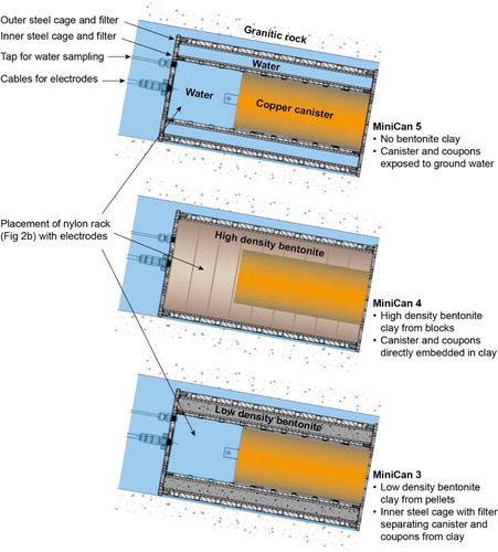
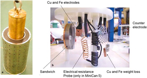
Figure 2. Design and assembly of the MiniCan packages. (a) The miniature copper-cast iron canister being inserted into the steel cage. (b) The nylon rack with electrodes and coupons, emplaced inside the steel cage, but outside the miniature canister.
The first package to be retrieved was MiniCan 3. This was done in 2011 and the results of the post-test examinations have been presented earlier [Citation2–6]. During the examination of MiniCan 3 it became apparent that microbial sulphate-reduction had a pronounced influence on the corrosion of cast iron components in this particular package with low density bentonite. In order to better understand the observations in MiniCan 3, it was decided to retrieve both packages 4 and 5, since these differed from package 3 in some important aspects as mentioned above. The retrieval of MiniCan 4 and 5 took place during the fall of 2015. Two complete reports of the post-test examination of these packages will be published by SKB [Citation7,Citation8]. In this proceeding, we will focus on the differences in the corrosion of iron and copper in the three packages of the MiniCan series that have been retrieved and examined until today.
Experimental
All copper components were made of phosphorous doped oxygen free copper (Cu-OFP) according to SKB’s design criteria for the full-scale canister of the KBS-3 concept (<5 weight ppm O, 30–100 weight ppm P). Copper electrodes and mass-loss coupons were polished with 600 grit emery paper and degreased before installation. The insert and other components of iron were made from cast iron. The bentonite clay used was MX-80 (high in montmorillonite) in the form of pellets in MiniCan 3 and prefabricated blocks and pellets in MiniCan 4. A typical ground water composition at 450 m depth at the Äspö HRL is shown in , while the development of the ground water composition in each of the MiniCan boreholes can be found in [Citation9] (chapter 4.1). Residual air made the environments inside the MiniCan oxidising right after closure of the boreholes. Continuous monitoring of Eh and potentials of various electrodes showed that it took at least 4 months for the experiments to reach the Eh of ca −300 mV vs. SHE that is typical for the Äspö ground water at this depth (see chapter 4.2 in [Citation9], or [Citation10]). During retrieval, handling and transportation the experimental packages were immersed in N2 saturated ground water in order to minimise air exposure and post-test oxidation of the surfaces. For the same purpose, samples for metallographic, chemical and microbiological examination were prepared inside an N2-filled glove-box (chapter 2 in [Citation7], chapters 5 and 6 in [Citation4]). Samples were placed in air tight boxes made of acrylic glass with a microscope glass lid attached with epoxy-based resin. The microscope glass enabled Raman spectroscopy under strictly anoxic conditions (Appendix 1 in [Citation4], Appendix 7 in [Citation7]). Fourier transform infra-red (FTIR) spectroscopy and X-ray diffraction (XRD) were applied after hours (FTIR) or days (XRD) of exposure to air (Appendix 1 in [Citation4], Appendices 8 and 9 in [Citation7]). Scanning electron microscopy (SEM) and energy dispersive X-ray analysis (EDX) were used to examine the topology of the sample surfaces and the elemental composition of deposits (Appendix 1 in [Citation4], Appendix 10 in [Citation7]). Gravimetric analysis was performed according to the standard SS-EN ISO 8407:2014 (Chapter 7.1.2 and 7.1.4 in [Citation4], Appendix 4 in [Citation7]). Sulphate reducing bacteria (SRB) were quantified using the method of most probable number (MPN), and the cultivation media had a composition based on the ground water composition at the Äspö site (Chapter 2 in [Citation3], and [Citation8]). Further details of the experimental methods and materials used in the post-test examination of MiniCan 3–5 can be found in other reports and papers [Citation3–5,Citation7,Citation8].
Table 1. Typical ground water composition at 450 m depth at the Äspö HRL.
Results and discussion
General observations and composition of surface films and deposits
When dismantling the experimental packages MiniCan 3 and 5, a thick black deposit was rather evenly distributed on electrodes and other specimens mounted on the nylon rack, while a thinner black deposit was unevenly distributed over the copper canister () [Citation4,Citation5,Citation7]. In MiniCan 4 there was no black deposit, but the surfaces were covered by a dark greyish layer of bentonite clay. In MiniCan 3, the thick black deposit surrounding the electrodes and other specimens mounted on the nylon rack were found to be partially amorphous but contained small (<5 µm) crystallites [Citation4]. XRD indicated that the black deposit contained magnetite (Fe3O4) and troilite (FeS), but also varying amounts of Si. Raman spectroscopy showed that the copper surface underneath the black deposit on the MiniCan 3 copper canister was covered with sulphide and graphitic carbon [Citation4,Citation5]. SEM-EDX of the copper shell revealed a thin film composed of Cu, Fe and S. Similar observations were made for the outside of the copper canister in MiniCan 5 [Citation7]. Raman showed that the surface film on the copper canister contained cuprite (Cu2O) and carbon, but SEM-EDX detected also Fe and S. It appears reasonable to assume that the origin of Fe, S and C on the surfaces in both MiniCan 3 and 5, is the corrosion of cast iron components mounted on the nylon rack. Quantitatively, all copper surfaces examined from the three MiniCan packages retrieved, had a background level of a few wt-% Fe in SEM-EDX, while many areas of copper surfaces in MiniCan 3 and 5 showed levels of more than 10 wt-% Fe, and occasionally even higher values were observed (Appendix 10 in [Citation7]).
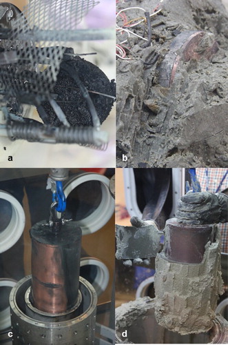
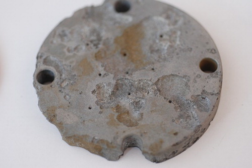
Figure 3. Appearance of the packages during dismantling under anoxic conditions. (a) The circular Fe–Cu sandwhich specimen of MiniCan 5 was covered with a thick black deposit, which was the case for most specimens of both MiniCan 3 and 5. (b) The sandwich specimen of MiniCan 4 appeared unaffected by the exposure, even the iron half had its colour and sharp edges remaining. (c) The canister of MiniCan 5 was partially covered with a black deposit and was thus very similar to MiniCan 3. (d) The canister of MiniCan 4 did not show any unevenly distributed deposits but was covered with a thin grey layer after removal of the clay.
On the copper electrodes mounted on the nylon racks in MiniCan 3 and 5, Raman analyses detected mainly Cu2O and mixed Cu and Fe sulphides, albeit some areas showed high content of Si. The surfaces of MiniCan 4 were generally more difficult to examine, since all components had been embedded in bentonite, which adhered to the surfaces.
Applying Raman at the iron electrodes of MiniCan 3, mainly a composition of iron sulphides was detected at corroded areas. Graphitic carbon was also detected but there were no indications of oxygen-containing corrosion products. In MiniCan 5, Raman similarly revealed mainly iron sulphides, however, when XRD was applied after a few days of air exposure, mainly ‘red rust’ was observed. The iron electrodes of MiniCan 4 were again difficult to examine spectroscopically, since they had been embedded in bentonite.
Corrosion of copper
Visually, all copper specimens appeared unaffected by corrosion after pickling to remove surface deposits. Macroscopically, no distinct areas of localised corrosion were found; the ∼100 µm machine marks of the canister surface remains (), as well as the sharp edges of the electrodes and coupons. At the microscopic level, SEM revealed a surface roughness with distinct pit-like defects of a few µm depth (Appendix 10 in [Citation2,Citation6,Citation7]). It is unclear if this morphology has appeared during ground water exposure or if the pits were present in the canister material at the initiation of exposure. The observed morphology is, however, in line with earlier observations of bentonite-embedded OFP copper exposed to ground water at the same geological site [Citation11,Citation12].
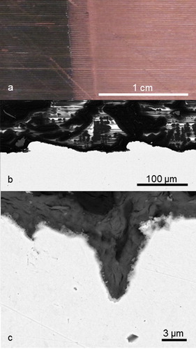
Figure 4. Morphology of the copper canister in MiniCan 4. (a) From a macroscopic perspective, the band structure (horizontal lines in the photo) introduced during manufacturing the miniature canister remains visibly intact over the whole canister surface. In the left part of the photo sulphides are still present (black), in the right part the surface has been cleaned using citric acid. (b) At the microscopic level, SEM reveals the same ∼100 µm band structure and distinct pits of a few µm depth. (c) Close-up of a distinct pit from the EB welding material of MiniCan 4.
The integrated corrosion rates in MiniCan 3 (low density bentonite), 4 (high density bentonite) and 5 (no bentonite) were 0.15, 0.02 and 0.11 µm/y respectively (). Although the single specimens admittedly provides no insight to the variation within each experimental package, it may be noted that the corrosion was about one order of magnitude lower in presence of highly compacted bentonite clay, than both in the absence or presence of low density bentonite clay [Citation4,Citation7]. Alternatively, one could view the three gravimetrically determined corrosion rates for copper as three repeated measurements from the same experiment. However, since the conductive conditions were rather different between for example MiniCan 4 (with compact clay) and MiniCan 5 (without clay), this is a questionable interpretation of the experiment.
Table 2. Integrated corrosion rates from gravimetric analysis of weight loss coupons installed in MiniCan 3, 4, and 5 (µm/y).
Corrosion of cast iron
For the specimens intended for gravimetric analysis, the integrated corrosion rate was around 500 µm/y in MiniCan 3, while only 2.1 and 3.2 µm/y in MiniCan 4 and 5, respectively (). However, the corrosion of iron was heterogeneous and varied between different cast iron specimens. While several samples from both MiniCan 3 and 5 showed extensive and localised corrosion damage corresponding to hundreds of µm/y by dimensional estimates (see e.g. sandwich specimen in ), only one of the iron electrodes of MiniCan 4 showed an attack of similar magnitude (Chapter 4.5.2 in [Citation7]), otherwise the iron components embedded in the compact bentonite clay were only slightly and evenly corroded (see e.g. sandwich specimen with sharp edges in (b)).
Figure 5. Wide shallow pits on outer iron surface of the Cu–Fe sandwich specimen of MiniCan 5 after pickling.
Development of water chemistry
Since the start of the experiment, the water chemistry has been monitored in boreholes and within the steel cages of MiniCan 3 and 5. In MiniCan 4 the steel cage was filled with compact bentonite, leaving no space for advective water and thus it could not be sampled. A common feature of the waters inside MiniCan 3 and 5 is a dramatic increase in [Fe2+], from initially 0.1–0.3 mg L−1 to 60–80 mg L−1 ([Citation10], chapter 4.1.2 in [Citation9]). On the other hand, [Fe2+] remained nearly unaffected (<1 mg L−1) in the bore holes. Sulphide levels have been measured at several occasions but the variations between the sampling dates are large and no clear trend is observed (Chapter 4.1.1 in [Citation9]). It should be noted though that large amount of sulphide has precipitated as iron sulphide (black deposits in e.g. (c)) inside the steel cages. While pH in the boreholes has remained around 7.5 since the start of the experiments, there has been a slight but varying decrease of the pH inside the experimental packages (Chapter 4.1.3 in [Citation9]).
Microbiology
Several types of microorganisms have been analysed in the waters and on the surfaces of MiniCan [Citation3,Citation8,Citation13], however, sulphide production by SRB is the microbial process that have the most pronounced influence on corrosion in anaerobic groundwater. Quantification of SRB in water samples showed that the MPNs of SRB in the water inside MiniCan 3 and 5 had increased from 2007 to 2015 [Citation8]. Already in 2007, when the experiments had been installed for less than a year, MPN indicated much higher numbers inside the MiniCan 2, 3 and 5 packages, than in the bore hole water [Citation3].
SRB were analysed in the bentonite clay of both MiniCan 3 and 4 [Citation3,Citation8]. In MiniCan 3, the dry density of the clay was 1300 kg m−3. The wet density was never measured after retrieval, however, compared to the clay of MiniCan 4 it appeared soft [Citation4]. The dry density of MiniCan 4 was 1600 kg m−3, aiming at a target wet density of 2000 kg m−3, which is a design criterion in the license application for the KBS-3 concept. The wet density of MiniCan 4 was measured at ten points along the canister and was found to vary between 1902 and 1959 kg m−3 with a mean value of 1930 (SD 0.02) kg m−3 (Chapter 2.2 in [Citation7]). This means that the target density was not fully achieved, either because of a slight expansion of the steel cage, or that too little dry mass was used during installation. The MPN of SRB in the low density bentonite of MiniCan 3 was nearly 105 cells/g [Citation3], albeit, it was only measured at one position. In MiniCan 4, the high density clay was sampled for SRB at several positions, giving MPN values from below the detection limit of 2 cells/g to 100 cells/g [Citation8]. The highest value was shown by a sample taken in the vicinity of the iron part of the sandwich specimen, however, viable SRB were found at varying positions in the clay. This difference of MPN of SRB in low- and high density clays is in good agreement with well controlled laboratory tests performed by Pedersen and co-workers [Citation14,Citation15].
In addition to water and clay samples, various surfaces inside the experiment packages were also sampled for analysis of SRB. There appears to be a correlation between MPN of SRB and corrosion of cast iron for the sandwich specimens of MiniCan 4 and 5. In MiniCan 4, the iron part of the sandwich had no visible corrosion and two samples from its surface gave around 20 cells/cm2 SRB. On the other hand, the iron part of the sandwich in MiniCan 5 was heavily corroded ((a) and ) and the MPN of SRB was 5 × 10² cells/cm2 at one point and 5 × 10⁵ cells/cm2 at another point [Citation8].
Corrosion scenario
Given the results available from the retrieval and examination of packages 3–5, the most plausible explanation for the extensive corrosion of cast iron seems to be the presence and metabolic activity of SRB that have colonised the metal surfaces and formed biofilms. Galvanic corrosion of iron has been considered since the iron half of the sandwich specimen in especially MiniCan 5 was so heavily corroded. However, this mechanism must be abandoned as a general explanation due to the extensive corrosion of some iron electrodes (connected by a carbon steel wire) and the mass-loss coupon (fastened and isolated by a nylon thread) in MiniCan 3 that were not in contact with copper or other more noble metals. The observed variability of corrosion between the different iron specimens of MiniCan 3 and 5 might be attributed to heterogeneous biofilm formation of SRB, but could possibly also be explained by variable wetting inside the steel cages of MiniCan 3 and 5, due to formation of gas bubbles after sampling campaigns. However, this could not explain the variable corrosion among iron specimens in MiniCan 4, which was not sampled internally due to the compact clay filling the space between the steel cage and the copper canister. At this stage, the cause behind the observed variation in the corrosion of different cast iron specimens in MiniCan remains unclear, however, SRB activity seems to be the most plausible cause.
For copper, the integrated rate of corrosion was low in all three packages (). Notably, the rate of corrosion in MiniCan 4 (high density bentonite) was as low as 0.02 µm/y, which is one order of magnitude lower than in MiniCan 3 and 5 (), but also lower than what has been observed in other large-scale field test of copper embedded in bentonite clay in saline ground water at the same geological site [Citation16]. Taking into account that it took several months for MiniCan 4 to reach fully reducing conditions [Citation9,Citation10] and that there thus was an initial period of oxygen-driven corrosion, it is not possible to say with certainty at which rate the sulphide corrosion of the mass-loss sample in MiniCan 4 has actually occurred, only that the integrated rate of 0.02 µm/y sets an upper limit. Raman spectroscopy detected both oxide and sulphide on the surface of the mass-loss specimen (chapter 4.5.3 in [Citation7]). Similarly, SEM-EDS indicated that the amount of O (3 wt-%) and S (6 wt-%) were similar on the surface of the copper mass-loss specimen of MiniCan 4, with the exception of some spots of bentonite clay (Appendix 10 of [Citation7]).
A final comment on earlier reported electrochemical measurements is appropriate. Unlike the gravimetric analysis presented and discussed herein, LPR (linear polarisation resistance) and ACI (AC impedance) measurements in the MiniCan series have previously indicated high (in some cases unrealistically high, meaning the electrodes would have been consumed) instantaneous corrosion rates of iron and copper (chapter 4.3 and 5.3 in [Citation9]). In the post-test analysis of MiniCan 3 these results were attributed to disturbances due to the presence of iron sulphide deposits on the surfaces of both the iron and copper electrodes in the experiment [Citation4,Citation5]. However, the copper electrodes in MiniCan 5 were also covered with black sulphur-rich deposits (figure 4–12 in [Citation7]), but there the rates interpreted from LPR and ACI were only a few µm/y (chapter 4.3 in [Citation9]). Notably, electrical resistance measurements of copper wires in MiniCan 2 (not yet retrieved) and MiniCan 5, have indicated average corrosion rates of 0.25 µm/y (MiniCan 2) and 0.39 µm/y (MiniCan 5) (chapter 4.4 in [Citation9]), which is more in line with the gravimetric results. Regarding the LPR and ACI measurements in MiniCan 4, no deposits of sulphide were detected, nevertheless, the direct embedment of the electrodes in the bentonite clay might have caused disturbances in the measurements.
Conclusions
MiniCan is a field test of certain aspects of corrosion in a KBS-3 type repository for spent nuclear fuel, originally consisting of five experimental packages, each containing a copper-cast iron canister supplemented with various electrodes and corrosion specimens, exposed to groundwater in the Äspö HRL since 2006. Three packages have been retrieved and examined regarding corrosion and surface chemistry of copper and iron. The main difference between the packages is that in MiniCan 3 the miniature canister was surrounded by low density bentonite, in MiniCan 4 it was embedded in high density bentonite, while MiniCan 5 had no bentonite present. The main conclusions from the post-test examination of MiniCan 3–5 are:
Locally extensive corrosion of cast iron specimens was observed in all three packages, although it was generally more widespread among the iron specimens in MiniCan 3 and 5 than in MiniCan 4. For some specimens the integrated corrosion rate was several hundreds of µm per year. The corrosion morphology of cast iron was heterogeneous with localised attacks in the form of wide pits of mm depth.
The integrated corrosion rate of mass-loss specimens of copper was 0.02 µm/y in MiniCan 4, thus one order of magnitude lower than in MiniCan 3 (0.15 µm/y) and MiniCan 5 (0.11 µm/y). The copper surfaces displayed a roughness with frequently occurring pits or defects at the µm scale.
SRB were present in ground water, in water inside the packages as well as in the bentonite clay and on the surfaces of various samples of iron and copper. High numbers of SRB were found in the low density bentonite of MiniCan 3, but viable SRB were found also in the high density bentonite of MiniCan 4. SRB activity is suggested to have a pronounced influence on the corrosion of iron, especially in the absence of high density clay (as in MiniCan 3 and 5).
Acknowledgments
The authors would like to acknowledge Nick Smart, Andy Rance, and Bharti Reddy at Amec Foster Wheeler, as well as Reza Javaherdashti, for useful discussions of the results presented herein. The retrieval of the packages was done by SKB staff at the Äspö HRL. Staff from Ninolab AB assisted the work in the glove box.
Disclosure statement
No potential conflict of interest was reported by the authors.
ORCID
Adam Johannes Johansson http://orcid.org/0000-0001-7686-7776
Andrew Gordon http://orcid.org/0000-0002-9863-0777
Lotta Hallbeck http://orcid.org/0000-0002-4999-1568
Additional information
Funding
References
- Smart NR, Rance AP. Minature canister corrosion experiment – results of operation to May 2008. Stockholm: SKB TR-09-20, Swedish Nuclear Fuel and Waste Management Co (SKB); 2009.
- Aggarwal S, Addepalli V, Smart N. Further metallographic analysis of MiniCan SCC test specimens. Stockholm: SKB R-15-11, Swedish Nuclear Fuel and Waste Management Co (SKB); 2015.
- Hallbeck L, Edlund J, Eriksson L. Microbial analyses of groundwater and surfaces during the retrieval of experiment 3, A04, in MINICAN. Stockholm: SKB P-12-01 29, Swedish Nuclear Fuel and Waste Management Co (SKB); 2011.
- Smart N, Rance A, Reddy B, et al. Analysis of SKB MiniCan Experiment 3. Stockholm: SKB TR-12-09, Swedish Nuclear Fuel and Waste Management Co (SKB); 2012.
- Smart NR, Rance AP, Reddy B, et al. In situ evaluation of model copper-cast iron canisters for spent nuclear fuel: a case of microbiologically influenced corrosion (MIC). Corros Eng Sci Technol. 2014;49:548–553. doi: 10.1179/1743278214Y.0000000213
- Smart N, Rose S, Nixon D, et al. Metallographic analysis of SKB MiniCan experiment 3. Stockholm: SKB R-13-35, Swedish Nuclear Fuel and Waste Management Co (SKB); 2013.
- Gordon A, Sjögren L, Taxen C. Post-test examination of packages 4 and 5 of the MiniCan field experiment. Stockholm: SKB TR-16-12, Swedish Nuclear Fuel and Waste Management Co (SKB); 2017.
- Hallbeck L, Johansson L, Edlund J, et al. Microbial analysis of ground water, bentonite and surfaces during the post-test analysis of packages 4 (A05) and 5 (A06) in the MiniCan experiment. Stockholm: SKB TR-16-13, Swedish Nuclear Fuel and Waste Management Co (SKB); 2017.
- Smart N, Reddy B, Nixon D, et al. Miniature Canister (MiniCan) Corrosion experiment Progress report 5 for 2008-2013. Stockholm: SKB P-14-19, Swedish Nuclear Fuel and Waste Management Co (SKB); 2015.
- Smart N, Rance A, Reddy B, et al. Further studies of in situ corrosion testing of miniature copper-cast iron nuclear waste canisters. Corros. Eng. Sci. Technol. 2011;46:142–147. doi: 10.1179/1743278210Y.0000000020
- Taxén C. Ytprofiler på kopparkapslar från deponeringshål 5 och 6 i försöksserien Prototyp. Stockholm: SKB P-13-50, Swedish Nuclear Fuel and Waste Management Co (SKB); 2013.
- Taxén C, Lundholm M, Persson D, et al. Analyser av koppar från prototypkapsel 5 och 6. Stockholm: SKB P-12-22, Swedish Nuclear Fuel and Waste Management Co (SKB); 2012.
- Lydmark S, Hallbeck L. Results report. Sampling and analyses of gases and microorganisms in the water from MINICAN in 2007, 2008 and 2010. Stockholm: SKB P-11-32, Swedish Nuclear Fuel and Waste Management Co (SKB); 2011.
- Bengtsson A, Edlund J, Hallbeck B, et al. Microbial sulphide-producing activity in MX-80 bentonite at 1750 and 2000kg m-3 wet density. Stockholm: SKB R-15-05, Swedish Nuclear Fuel and Waste Management Co (SKB); 2015.
- Bengtsson A, Blom A, Hallbeck B, et al. Microbial sulphide-producing activity in water saturated MX-80, Asha2012 and Calcigel bentonite at wet densities from 1500 to 2000kg m−3. Stockholm: SKB TR-16-09 report in press; 2016.
- Rosborg B. Recorded corrosion rates on copper electrodes in the Prototype Repository in the Äspö HRL. Stockholm: SKB R-13-13, Swedish Nuclear Fuel and Waste Management Co (SKB); 2013.