
ABSTRACT
Canada is currently considering Cu-coated carbon steel containers for the long-term storage of used nuclear fuel in a deep geological repository. The Cu coating provides a corrosion-resistant barrier, protecting the underlying steel from coming into contact with groundwater. However, galvanically accelerated corrosion of steel is possible if there is a defect through the Cu coating. To investigate this scenario, the progression of steel corrosion at the base of a simulated though-coating defect was imaged using synchrotron X-ray micro-computed tomography. Results show that coatings produced using different methods (cold spray, annealed cold spray, electrodeposition) lead to different corrosion propagation geometries. These findings can be used for modelling steel corrosion at a though-coating defect under deep geological repository conditions.
This paper is part of a supplement on the 6th International Workshop on Long-Term Prediction of Corrosion Damage in Nuclear Waste Systems.
Introduction
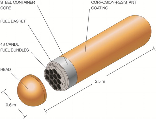
Within the multi-barrier system proposed for the permanent disposal of spent nuclear fuel, the primary engineered barrier is the sealed metallic container. The present Canadian container design involves a Cu-coated carbon steel vessel, , with a coating thickness of a few millimetres. The coating methods being considered are electrodeposition for the container body and head, before filling the container with fuel, and annealed cold spray on the ‘weld zone’, which is the region where the steel container will be seal-welded in the used fuel packing plant [Citation1,Citation2].
Figure 1. Proposed design for Canadian used nuclear fuel containers.
After the containers are emplaced in a deep geological repository (DGR), the heat generated by radioactive decay in the fuel will drive humidity from the environment close to the container walls and negligible corrosion will be expected. However, as containers cool, moisture will return and repository conditions will then evolve from humid, warm, and oxidising to saturated, cool, and anoxic. This evolution in redox conditions will lead to a number of possible corrosion processes [Citation3], most of which will be short term and cease once anoxic conditions are established. However, two processes could persist beyond this initial period: (i) the reaction with sulphide, which is expected to be present in the groundwater due to the action of sulphate reducing bacteria in the bentonite clay surrounding the container and potentially the presence of sulphide-rich minerals (such as pyrite) [Citation4]. (ii) Corrosion of steel if the container is emplaced with a through-coating defect, an unlikely situation that should be avoided by proper inspection of the container before emplacement. In the presence of dissolved O2 in the groundwater, this second process would occur galvanically [Citation5–7], with steel oxidation/dissolution at the base of the defect being supported by O2 reduction on the adjacent Cu surface. When all the O2 is consumed, corrosion could continue, albeit at a considerably reduced rate, since steel remains unstable in H2O without being galvanically coupled to Cu. In addition, whether or not the two processes ((i) and (ii)) could occur simultaneously and interact remains undetermined.
We are using synchrotron X-ray micro-computed tomography (micro-CT) to follow the latter corrosion process non-destructively, with the long-term objective of calculating the volume of metal lost to corrosion and observing, directly, the morphology of propagation of the corrosion process. In this publication, we compare the corrosion of the steel at the base of simulated defects in cold spray, annealed cold spray, and electrodeposited coatings in oxygenated chloride solutions. Experiments with other O2 levels are under way.
Experimental methodology
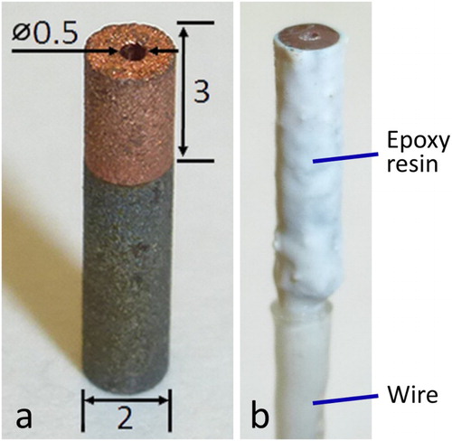
The 2 mm (diameter) samples were cut from A516 grade 70 carbon steel plates that had been Cu-coated via cold spray or electrodeposition; details of the coating processes have been given elsewhere [Citation2,Citation3]. Cold spray specimens were cut as-deposited and a portion of these were annealed at 350°C for 1 h under Ar gas. To simulate a defect, a hole (approx. 0.5 mm in diameter) was drilled through the 3 mm-thick coating down to the Cu/steel interface, (a). For all specimens, the top Cu surface was wet-polished by hand with SiC paper to a P1200 grit finish, using a minimal amount of water and drying the sample frequently to ensure that the steel at the base of the drilled hole remained dry. To enable electrochemical measurements, a wire was soldered to the steel substrate and heat-shrink PTFE tubing was used to cover the wire. Samples were sonicated in methanol before being coated with Torr Seal® epoxy (Kurt J. Lesker Canada Inc., Concord, Canada) on all sides except for the top Cu surface, (b). Torr Seal® epoxy was used because, unlike many other epoxies, it does not degrade when exposed to synchrotron X-rays, which are extremely intense. Before beginning an experiment, we wet-polished the top Cu surface to a P2400 grit finish using SiC paper, sonicated the sample in methanol, and dried it in a stream of Ar.
Figure 2. Cu-coated steel sample with a hole drilled through the Cu to the steel; (a) uncoated, (b) with a wire connector covered with PTFE and coated with Torr Seal® epoxy. Dimensions are in millimetres.
Prepared specimens were immersed in pH neutral, O2-sparged, 3 mol L−1 NaCl (reagent grade) solution to simulate the saline conditions possible within a Canadian DGR. Synchrotron micro-CT, performed at the Advanced Photon Source (Argonne National Laboratory, Argonne, IL, U.S.A) using beamline 2-BM-A, was used to image non-destructively the corrosion damage within the defect over a 42 h exposure period. The resulting data were reconstructed using TomoPy, an open-sourced, Python-based framework [Citation8].
Results and discussion
Micro-CT image slices are shown in for as-deposited cold spray, annealed cold spray, and electrodeposited Cu coatings, respectively. Within these figures, specimens with 0 h sample exposure to solution and 42 h sample exposure to solution are indicated by (a) and (b), respectively, while upper and lower images show vertical and horizontal slices, respectively. The vertical slices traverse the centre of the defect, and show how corrosion has penetrated into the steel over the 42 h exposure period. The horizontal slices selected were recorded at the Cu/steel interfaces and show how damage has propagated along these interfaces.
Figure 3. Synchrotron micro-CT vertical and horizontal image slices of the cold spray Cu/steel interface after exposure to O2-sparged 3 mol L−1 NaCl solution for 0 h (a) and 42 h (b). The accumulated corrosion products are highlighted in the 42 h vertical image slice.
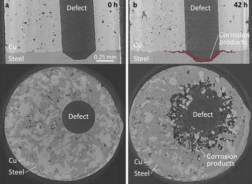
Figure 4. Synchrotron micro-CT vertical and horizontal image slices of the annealed cold spray Cu/steel interface after exposure to O2-sparged 3 mol L−1 NaCl solution for 0 h (a) and 42 h (b). The accumulated corrosion products are highlighted in the 42 h vertical image slice.
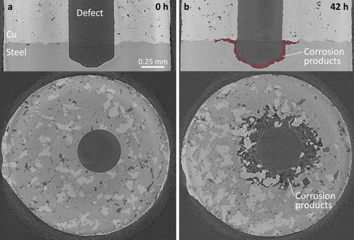
Figure 5. Synchrotron micro-CT vertical and horizontal image slices of the electrodeposited Cu/steel interface after exposure to O2-sparged 3 mol L−1 NaCl solution for 0 h (a) and 42 h (b). The accumulated corrosion products are highlighted in the 42 h vertical image slice.
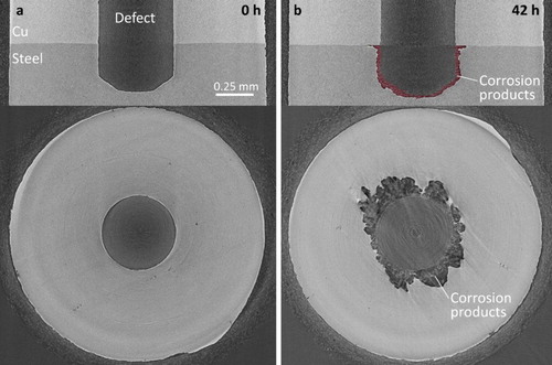
Areas in the images corresponding to Cu appear lightest because the density and absorption coefficient of Cu are greater than those of carbon steel [Citation9], making X-ray intensity transmission through copper weaker. Areas corresponding to steel are the second lightest shade of grey and relatively uniform dark grey indicates empty space. Corrosion products appear as a mix of dark grey shades since they are non-uniform in density and lower in density than steel. To highlight their location, they are shown in red in the 42 h vertical image slices. That these areas are composed of corrosion products has been confirmed analytically on cross sections cut on corroded specimens [Citation3]. Additionally, the dark locations within the bulk of the cold spray coatings show the coating porosity; however, it should be emphasised that this coating process had not been optimised when these samples were produced. The layer of epoxy appears as a mottled layer on the outer surface of the samples.
For the cold spray and annealed cold spray specimens, and , respectively, the (upper) vertical image slices show that corrosion both penetrated into the steel at the base of the defect and spread along the Cu/steel interface. The corrosion products have previously been identified via Raman spectroscopy of cross sections [Citation3], as a mixture of iron oxyhydroxides (α-FeOOH, β-FeOOH, and γ-FeOOH) and maghemite (γ-Fe2O3). The presence of Fe(III)-containing corrosion products confirms that highly oxidising conditions existed for some period within the defect. Experiments conducted on similarly defective electrodes [Citation3] show that redox conditions within the defect evolve over longer exposure periods of up to 50 days.
The dark, approximately circular areas observed in the (lower) horizontal image slices in and , recorded at the Cu/steel interfaces, show that corrosion also spread radially from the defect along the Cu/steel interface, leading to the deposition of corrosion products as previously shown in the analyses of cross sections [Citation3]. The unevenness of these interfaces, which occurs as a result of interfacial distortions during the cold spray deposition process [Citation1,Citation2], leads to the observation of ‘patches’ of Cu and steel in the horizontal image slices. The gradations in grey colour in the aforementioned dark areas show corrosion products are associated with these locations. However, in these images we are dominantly interested in illustrating the extent of corrosion which is indicated by these dark areas. The smaller radius of this corroded interfacial region around the defect in the annealed specimen, , indicates that this interfacial corrosion process is less extensive than it is on the as-deposited specimen. For the electrodeposited specimen, , the corrosion penetration into the steel at the base of the defect, indicated by the thickness of the accumulated corrosion product deposit is similar to that for the two cold-spray specimens, however, the distribution of corrosion damage along the Cu/steel interface is considerably reduced.
Previously, we have examined the quality of these interfaces using electron backscatter diffraction (EBSD) on metallographic cross sections [Citation2,Citation3] and determined the strength of coating adhesion according to the ASTM standard E08 procedure [Citation10]. Scanning electron micrographs have shown the Cu/steel interfaces of cold spray specimens to be physically deformed by the high velocity impact of the Cu particles used in the cold spray process, while EBSD has detected a high degree of interfacial strain [Citation2,Citation3]. Annealing led to a considerable reduction in strain and a slightly more regular coating/substrate boundary. The adhesive strength of the cold spray copper to the steel was 68–98 MPa for the as-deposited specimen, values that are only slightly reduced by annealing (62–72 MPa). By comparison, the electrodeposit/steel interface has proven to be even and relatively strain-free, except for a thin layer of very small grains located at the interface, and the copper is very strongly bonded to the steel (286–373 MPa). From these results, it is reasonable to infer that the factors influencing the greater extent of interfacial corrosion on the cold spray samples vs. the electrodeposited ones are the material strain, interface non-uniformity and adhesive strength of the coating to the substrate.
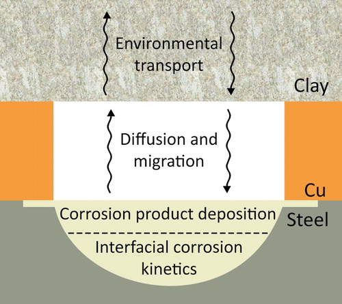
Besides providing an unequivocal description of the damage distribution, micro-CT data can be used to calculate the volume of material (steel in this case) lost to corrosion. By estimating the volume loss and the steel density, the mass loss can be calculated and readily converted to an equivalent electrochemical charge using Faraday’s law of electrolysis. For galvanically coupled corrosion involving O2 reduction on the surface of the Cu coating, the extent and distribution of damage could then be related to the available inventory of O2 (or radiolytic oxidants) in a DGR. Calculations such as these are part of our continuing research, along with electrochemical and micro-CT measurements in solutions containing various O2 concentrations (including anoxic conditions) to determine the evolution of damage as a function of cathodic kinetics. Other continuing work includes the development of a finite element model (based on a COMSOL framework) of the damage that can accumulate at a coating defect. The basic processes which must be incorporated into such a model, including transport processes in the surrounding compacted clay, are illustrated in . The direct quantitative micro-CT measurements of the extent of corrosion then offer a means to validate such a model.
Figure 6. Schematic illustration of the processes to be considered in a finite element model for the corrosion of steel at a through-Cu coating defect.
Summary and conclusions
Micro-CT measurements on Cu-coated steel specimens with a through-coating defect exposing the substrate steel were made in oxygenated 3.0 mol L−1 NaCl. The behaviours of cold spray, annealed cold spray and electrodeposited coatings were compared over exposure periods of 42 h. For all specimens, the volumes of corrosion damage into the steel substrate at the base of the coating defect were approximately the same, despite differences in corrosion propagation geometries. For the two cold spray specimens, corrosion spread radially from the defect along the Cu/steel interface, especially on the unannealed specimen. For the electrodeposited specimen only minimal interfacial damage occurred. Factors related to corrosion of the coating-steel interfaces include the roughness, strain and adhesion of the coatings to the substrate.
Disclosure statement
No potential conflict of interest was reported by the author(s).
ORCID
Thalia E. Standish http://orcid.org/0000-0001-6102-4135
Peter G. Keech http://orcid.org/0000-0001-8435-628X
Additional information
Funding
References
- Keech PG, Vo P, Ramamurthy S, et al. Design and development of copper coatings for long term storage of used nuclear fuel. Corros Eng Sci Technol. 2014;49:425–430. doi: 10.1179/1743278214Y.0000000206
- Jakupi P, Keech PG, Barker I, et al. Characterization of commercially cold sprayed copper coatings and determination of the effects of impacting copper powder velocities. J Nucl Mater. 2015;466:1–11. doi: 10.1016/j.jnucmat.2015.07.001
- Standish T, Chen J, Jacklin R, et al. Corrosion of copper-coated steel high level nuclear waste containers under permanent disposal conditions. Electrochim Acta. 2016;211:331–342. doi: 10.1016/j.electacta.2016.05.135
- King F. A review of the properties of pyrite and the implications for corrosion of the copper canister. 2013. (SKB TR-13-19).
- Baboian R. Galvanic corrosion. ASM handbook, volume 13: corrosion: fundamentals, testing, and protection. 2nd ed. Materials Park (OH): ASM International; 2003. p. 210–213.
- Whitman WG, Russell RP. The natural water corrosion of steel in contact with copper. Ind Eng Chem. 1924;16:276–279. doi: 10.1021/ie50171a024
- Smart NR. Corrosion behavior of carbon steel radioactive waste packages: A summary review of Swedish and U.K. research. Corrosion. 2009;65:195–212. doi: 10.5006/1.3319128
- Gürsoy D, De Carlo F, Xiao X, et al. Tomopy: a framework for the analysis of synchrotron tomographic data. J Synchrotron Radiat. 2014;21:1188–1193. doi: 10.1107/S1600577514013939
- Berger MJ, Hubbell JH, Seltzer SM, et al. XCOM: Photon Cross Section Database (version 1.5) [Internet]. Gaithersburg, MD: National Institute of Standards and Technology; 2010 [cited 2016 Sep 7]. Available from: http://physics.nist.gov/PhysRefData/Xcom/html/xcom1-t.html
- ASTM International. Standard test methods for tension testing of metallic materials, ASTM E8/E8M-08. West Conshohocken (PA): ASTM International; 2008; p. 1–27.