
 ?Mathematical formulae have been encoded as MathML and are displayed in this HTML version using MathJax in order to improve their display. Uncheck the box to turn MathJax off. This feature requires Javascript. Click on a formula to zoom.
ABSTRACT
The Nuclear Waste Management Organization is responsible for the implementation of Adaptive Phased Management, the federally approved plan for the safe long-term management of Canada’s used nuclear fuel. Under this plan, used nuclear fuel will ultimately be placed within a deep geological repository in a suitable host rock formation. The repository’s engineered barrier system (EBS) comprises the used fuel container and engineered sealing materials. The EBS is a key component of the design of the underground repository. The Canadian EBS consists of a carbon-steel, copper-coated used fuel container that is encapsulated within a bentonite buffer box. Corrosion of copper and steel in the postclosure environment of a deep geological repository is expected to be very slow. This paper presents an estimate of these corrosion rates, forming the basis for assessing postclosure safety of a repository system and building confidence in the long-term performance of a Canadian repository for used nuclear fuel.
This paper is part of a supplement on the 6th International Workshop on Long-Term Prediction of Corrosion Damage in Nuclear Waste Systems.
Introduction
Before specific sites have been identified for detailed examination, generic studies are used to illustrate the long-term performance and safety of the multi-barrier repository system within various geological settings. Assessing the postclosure safety of the most recent conceptual repository design must incorporate the Canadian engineered barrier system (EBS). The used fuel container is a key component of the EBS and therefore the value of the safety assessment will depend greatly on how performance of the container is assessed.
To be effective, the safety assessment must be robust and have an appropriate balance of model simplicity without excess conservatism. This paper considers how to approach a postclosure safety assessment of the Canadian EBS, with focus on the container failure model. Models representing the Normal Evolution Scenario are presented, including calculations and results.
Corrosion of the copper coating
As the repository environment becomes anoxic and dominated by reducing conditions, corrosion of the copper layer protecting the containers will occur primarily by reaction with groundwater sulphide and be limited by the rate of transport of sulphide through the buffer to the container surface.
Detailed characterisation of specific sites will include comprehensive assessments of the deep groundwater, including dissolved sulphide concentrations. To date, assessments of the deep groundwaters in the Canadian Shield provide some information on sulphide concentrations. AECL reported dissolved sulphide to be ‘largely absent’ [Citation1]. Based on data in AECL field records (unpublished), any measurable groundwater sulphide is typically less than 1 µM; a single-point maximum was measured at 2.7 µM. There is typically no sulphide found in the groundwater in sedimentary rock [Citation2]. This suggests groundwater within the host rock for the Canadian repository will contain almost no sulphide – likely below detection limits.
Calculations presented here assume that the groundwater sulphide concentration is 1 µM, significantly higher than concentrations typically found in groundwaters in the Canadian Shield. Models developed by Briggs et al. [Citation3] were used to calculate the rates of transport of sulphide from the host rock through the EBS to the container surface. Rates of sulphide transport were then used to calculate the corrosion rates presented in : corroding at a rate of 0.026 nm per year, a 3 mm thick layer of copper will protect the inner steel container for over 100 million years.
Figure 1. Reducing thickness of the copper barrier due to reaction with groundwater sulphide.
Defects in the copper coating
Design and characterisation of the quality control (QC) technology that will confirm the thickness and continuity of the copper coating is continuing. Work to date suggests detection of coating defects that are 0.8 mm or larger is a realistic QC threshold. For a through-layer defect to pass QC inspection undetected is unlikely, perhaps unrealistic.
The impact of an undetected defect on the local corrosion rate will depend partly on the size and shape of the defect. proposes some examples of hypothetical defects in a nominal 3 mm copper coating. If a defect results in locally thinner copper, steel beneath a defect may be exposed to groundwater earlier than calculations in suggest. presents the time to exposed steel beneath a defect as a function of the defect size; calculations assume that defects are oriented for maximum reduction in the local coating thickness; also that corrosion of copper local to the defect is not slow relative to the uniform corrosion rate.
Figure 2. Hypothetical defects in the copper coating.
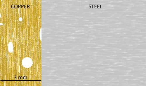
Figure 3. Time to exposed steel beneath defects in a nominal 3 mm copper coating.
Corroding at a rate of 0.026 nm per year, a 3 mm thick layer of copper with no defects will protect the inner steel container for over 100 million years; steel beneath a 0.8 mm defect in the copper layer will be protected for over 70 million years; steel beneath a 2 mm defect will be protected for over 25 million years.
For the purposes of assessing repository performance, the postclosure safety assessment of the Canadian EBS will consider a failure in the copper coating and inspection process that could lead to containers placed in the repository with small defects. Based on the results presented here, it may be reasonable and conservative to assume that defects passing QC inspection undetected would lead to exposed steel only after more than 10 million years. Defects leading to exposed steel within the one million year timeframe of the assessment would require a fairly large defect, greater than 2 mm, as well as elevated groundwater sulphide concentrations. Exposed steel upon placement in the repository would require a through-layer defect in a nominal 3 mm copper coating to pass QC inspection undetected, which may be unrealistic.
Corrosion of the steel wall
If defects in the copper coating lead to exposed steel, groundwater will begin to corrode the exposed steel and may eventually perforate the wall of the container. The steel corrosion models used by the NWMO were developed by King [Citation4]. Corrosion rates are temperature-dependent. The calculations discussed here use the container surface temperatures determined by Guo [Citation5], shown in . (This is a representative case, in the final design some containers may approach 100°C peak temperature.)
Figure 4. Evolution of container temperature.
The postclosure repository environment will become anoxic within a relatively short time. Under these conditions, magnetite is the likely corrosion product, particularly if the system is carbonate-limited or only partially saturated; the rate of magnetite-generating corrosion is based primarily on work by Newman et al. [Citation6]; passivation is implicit. Siderite may be the primary corrosion product if the system has sufficient carbonate available and is fully saturated; the rate of siderite-generating corrosion is based on the literature values [Citation4]; again, passivation is implicit. Rates for both forms of corrosion are shown in , based on the container temperatures provided in . Siderite-generating corrosion is much faster than magnetite-generating corrosion – more than 10 times faster if temperatures are below ∼40°C; in , the temperature becomes less than 40°C around 14,000 years postclosure.
Figure 5. Evolution of steel corrosion rates.
The steel corrosion models developed by King [Citation4] apply to an open surface with no protective copper coating, referred to here as open-surface corrosion. The models consider a corrosion front advancing uniformly through steel, where the corrosion product steadily suppresses the corrosion rate. These models may be adapted to reflect corrosion through a defect in the copper coating, referred to here as defect corrosion. illustrates the geometry of defect corrosion: the corrosion front is expected to advance radially from the defect, resulting in an expanding hemisphere of corroded steel. This is supported by the X-ray microtomography image included in , presenting early results from laboratory experimentsFootnote1 assessing defect corrosion of copper-coated steel.
Figure 6. Conceptual illustration of defect corrosion (left panel); the X-ray microtomography image (right panel) presents early results from laboratory experiments.
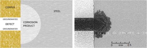
Assume the material properties of the corrosion product (bulk porosity, ion diffusivity, etc.) are the same under open-surface and defect corrosion. Considering the hemispherical corrosion front, it is then reasonable to infer that transport of the components of the corrosion reaction becomes dependent on the size of the defect. In this case, the rate of defect corrosion can be shown to relate to open-surface corrosion as follows:
Open-surface corrosion
Defect corrosion
(see solution for spherical diffusion)
Solution for spherical diffusion
where r is corrosion depth; r0 is radius of defect in copper corrosion barrier; ρ is density; A is area; t is time; X is the stoichiometric coefficient of corrosion ion species; Jr is flux of corrosion ion species; Deff is effective diffusivity of corrosion product; mW is molecular weight; k is the integration constant; CHi is concentration of corrosion ion species in bulk solution; CLo is concentration of corrosion ion species at the corroding surface.
This relationship includes several potential conservatisms:
For r < r0, calculations assume open-surface corrosion.
Corrosion products grown within the protected environment of the defect may be more homogenous and, consequently, more resistant to transport of reaction components.
Expansion of corrosion product relative to corroded steel may further limit transport.
Even if sufficient carbonate is available, this configuration may inhibit siderite-generating corrosion.
In addition, calculations presented here respect the lower bounds imposed on the open-surface corrosion models [Citation4]. This addresses the uncertainty implicit in modelled defect corrosion rates not yet confirmed experimentally. Corrosion model calculations are shown in for both magnetite- and siderite-generating corrosion; defect corrosion calculations assume a 1 mm diameter through-copper defect.
Figure 7. Adaption of open-surface corrosion models for defect corrosion, illustrated for magnetite-generating corrosion (left panel) and siderite-generating corrosion (right panel).
It should be noted that these calculations include corrosion rates driven by elevated temperatures associated with the first few thousands of years postclosure. As discussed above, for exposure of steel beneath a defect in the copper coating to occur within one million years would require a fairly large defect, greater than 2 mm, as well as elevated groundwater sulphide concentrations. The steel corrosion calculations presented here assume exposed steel upon placement of containers in the repository. This would require a through-layer defect in a nominal 3 mm copper coating to pass QC inspection undetected, which may be unrealistic.
Assuming exposed steel upon container placement, for corrosion to perforate the container wall in much less than one million years would require the through-copper defect to occur within the container closure zoneFootnote2 and for sufficient transport of carbonate to sustain siderite-generating corrosion at the corroding surface.
Realistically, the overall time required for groundwater to perforate a container is expected to exceed tens of millions of years.
Conclusion
The postclosure safety assessment of the Canadian EBS design will consider a failure in the copper coating and inspection process that could lead to containers placed in the repository with small defects. Corrosion modelling results presented here suggest that it may be reasonable and conservative to assume that defects passing QC inspection undetected would lead to exposed steel only after more than 10 million years. Once steel is exposed to groundwater, corrosion model calculations find that, realistically, the overall time required for groundwater to perforate a container will exceed tens of millions of years.
From these results, used fuel containers are expected to remain intact essentially indefinitely, with no releases (and no dose consequences) within the one million year timeframe of the postclosure safety assessment. This assumes all natural and engineered barriers function as intended, defined as the Reference Case of the Normal Evolution Scenario. However, in order to illustrate postclosure performance of the rest of the repository system, the Base Case of the Normal Evolution Scenario will consider scenarios involving container failures. In this way, case studies can assess postclosure dose implications of the Canadian EBS design.
Acknowledgements
The author would like to thank T.E. Standish for providing the X-ray microtomography image used to produce .
Disclosure statement
No potential conflict of interest was reported by the author.
ORCID
Erik P. Kremer http://orcid.org/0000-0002-9275-7814
Notes
1 Standish et al. [Citation7] describe the equipment and methodology for experimental work similar to that depicted in .
2 The thickness of the steel wall varies across the container: the cylinder section is 46.2 mm thick; the hemi-heads are 30 mm thick; the closure zone includes a narrow, partial-penetration weld with a minimum 8 mm thickness.
References
- Gascoyne M. The evolution of redox conditions and groundwater chemistry in recharge-discharge environments on the Canadian shield. Pinawa (MB): Atomic Energy of Canada Limited; 1996. (AECL-11682)
- Intera Engineering Limited. OPG’s deep geologic repository for low & intermediate level waste, descriptive geosphere site model. Toronto (ON): Nuclear Waste Management Organization (CA); 2011. (NWMO DGR-TR-2011-24)
- Briggs S, McKelvie J, Keech P, et al. Transient modelling of sulphide diffusion under thermal conditions typical of a deep geological repository. In: Hall DS, Keech PG, King F, editors. Proceedings of the 6th International Workshop on Long-Term Corrosion Damage in Nuclear Waste Systems; 2016 May 9–12; Toronto, ON.
- King F. Consequences of the general corrosion of carbon steel used fuel containers for gas generation in a DGR. Toronto (ON): Nuclear Waste Management Organization (CA); 2013. (NWMO TR-2013-16)
- Guo R. Thermal response of a Mark II conceptual deep geological repository in crystalline rock. Toronto (ON): Nuclear Waste Management Organization (CA); 2016. (NWMO TR-2016-03)
- Newman RC, Wang S, Kwong G. Anaerobic corrosion studies of carbon steel used fuel containers. Toronto (ON): Nuclear Waste Management Organization (CA); 2010. (NWMO TR-2010-07)
- Standish TE, Zagidulin D, Ramamurthy S, et al. Galvanic corrosion of copper-coated carbon steel for used nuclear fuel containers. In: Hall DS, Keech PG, King F, editors. Proceedings of the 6th International Workshop on Long-Term Corrosion Damage in Nuclear Waste Systems; 2016 May 9–12; Toronto, ON.