
 ?Mathematical formulae have been encoded as MathML and are displayed in this HTML version using MathJax in order to improve their display. Uncheck the box to turn MathJax off. This feature requires Javascript. Click on a formula to zoom.
ABSTRACT
The corrosion behaviour of nuclear fuel waste containers depends on the near-field environmental conditions, which may differ significantly from those in the host rock, especially during the early thermal-saturation transient phase. Although it is widely accepted that, in broad terms, the repository evolves from initially warm and oxidising to cool and anoxic in the long term, it is important to understand the detailed nature of the near-field environment in order to predict the corrosion behaviour of the container with confidence. Available information about the near-field environment is briefly reviewed and the expected time dependence of various environmental parameters is defined for a bentonite-backfilled deep geological repository. Although the focus is on a Canadian repository design for copper-coated containers in crystalline or sedimentary host rocks, the discussion is broadly applicable to a variety of container materials and repository designs and locations. Some implications for the corrosion behaviour of the container are also considered.
This paper is part of a supplement on the 6th International Workshop on Long-Term Prediction of Corrosion Damage in Nuclear Waste Systems.
Introduction
Over the past 40 years, it has become generally agreed that the post-closure deep geological repository (DGR) environment will evolve from initially warm and oxidising conditions to a long-term cool and anoxic phase. This evolution will significantly impact the type(s) of corrosion, the associated rate(s), and the performance of the used nuclear fuel container. In a companion study of the localised corrosion behaviour of copper [Citation1], it was necessary to define a range of anticipated solution conditions (pH, anion concentrations, etc.). However, these conditions remain difficult to generically define, owing to site-specific parameters and insufficient historical consideration of the nature of the near-field environment.
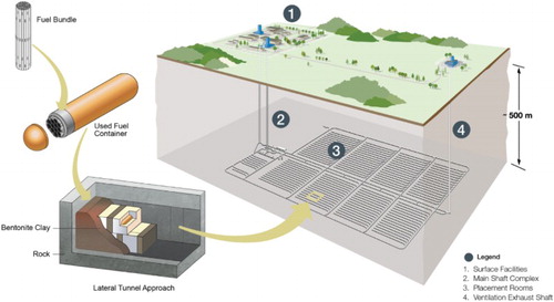
Here, we review the existing information on the nature of the near-field environment, predict its evolution in a Canadian DGR, and draw conclusions relevant to bentonite-backfilled repositories in other geological settings. Much of the discussion is applicable to generic container designs; although the Canadian copper-coated design () is described in detail. Both ‘near-field’ (e.g. within a few metres of the container) and ‘far-field’ conditions are considered; although the focus is on the evolution of the former.
Figure 1. Conceptual design of a deep geological repository for used fuel in Canada showing lateral in-room emplacement of copper-coated containers in compacted bentonite ‘buffer boxes’.
Previous work on the nature of the near-field environment
Our current understanding of the near-field environment comes from bench-scale experiments [Citation2–4], large-scale in situ tests [Citation5,Citation6], modelling studies, and characterization of backfilling materials. Obtaining analytical data on the composition of bentonite pore water, however, is difficult because the action of squeezing saturated bentonite can alter the nature of the collected liquid sample [Citation7]. In response, researchers have used thermodynamic models to predict pore-water compositions [Citation8–10]. Whereas some models are capable of predicting the time-dependent effects of saturation and thermal gradients [Citation11,Citation12], this approach is generally limited to pore-water compositions at equilibrium with the ground water.
The design of the DGR also establishes limits on certain environmental parameters. For example, since deep ground waters are anoxic, the only O2 available for corrosion is that trapped in the repository at the time of its closure. The inventory of trapped O2 is determined by the properties of the buffer and backfill materials, i.e. volume, porosity, and saturation. As discussed in more detail below, the properties of the buffer and bentonite are also important in determining the initial pore-water compositions and the transport rates of reactants towards, and of corrosion products away from the container surface.
Evolution of environmental parameters of importance for container corrosion
A number of environmental parameters can affect the corrosion behaviour of the container. Some of these are determined by the host site, others by the repository design. It is possible, however, to draw broad conclusions about how the environment will evolve over time and, thus, affect the container corrosion behaviour. Here we focus on the initial thermal-saturation transient phase, although some aspects of the long-term evolution are also discussed.
Ground water
A natural starting point for this work is to examine the composition of deep ground waters, which tend to be saline for crystalline and sedimentary host rocks in Canada, with 0.1 ≤ [Cl−] ≤ 5 mol L−1 and with Na+ and Ca2+ as the dominant cations (). Sulphate and bicarbonate are present at much lower concentrations. However, it cannot be over-emphasized that the container will not be in contact with the ground water itself, but with the pore water in the bentonite. Thus, during the early oxic transient phase the nature of the ground water is of secondary importance in determining the pore-water composition; although it is important in determining the long-term corrosive conditions. It should be noted that, unlike deep ground waters in Sweden and Finland [Citation13], the corresponding waters in potential locations for a Canadian repository are free of dissolved sulphide. Therefore, the only source of sulphide in the repository will be microbial activity that could occur at the buffer/rock interface with the subsequent diffusion of HS− to the container surface.
Table 1. Characteristic Canadian ground water compositions in crystalline (CR-10) and sedimentary (SR-270-PW) host rocks.
Temperature and heat transfer
The time dependence of the container surface temperature is reasonably well known [Citation14], although it will be dependent to some extent on the site-specific saturation behaviour, which will affect the thermal conductivity of the buffer materials. In addition to the container surface temperature, the presence of temperature gradients through the buffer materials may impact the corrosion behaviour, for instance, due to spatial variations in reaction rates and solubility. (a) shows the predicted time-dependent container surface temperature of the current Canadian DGR design in crystalline host rock [Citation14].
Figure 2. Best estimate of the time-dependent evolution of a number of environmental parameters important for corrosion of the container for a Canadian deep geological repository based on the use of copper-coated containers emplaced in buffer boxes. (a) is taken from Guo [Citation14]; (b,c) are hypothetical saturation profiles based on assumed DGR saturation times of 50 and 5 000 years, respectively; (d) is based on the observed rate of O2 consumption from Müller et al. [Citation22] and the maximum absorbed dose rates from Marco et al. [Citation23] and an assumed half-life of 30 years; the basis of (e) is described in detail in the text, and; (f) is based on the modelling approach described in Briggs et al. [Citation29].
![Figure 2. Best estimate of the time-dependent evolution of a number of environmental parameters important for corrosion of the container for a Canadian deep geological repository based on the use of copper-coated containers emplaced in buffer boxes. Figure 2(a) is taken from Guo [Citation14]; Figure 2(b,c) are hypothetical saturation profiles based on assumed DGR saturation times of 50 and 5 000 years, respectively; Figure 2(d) is based on the observed rate of O2 consumption from Müller et al. [Citation22] and the maximum absorbed dose rates from Marco et al. [Citation23] and an assumed half-life of 30 years; the basis of Figure 2(e) is described in detail in the text, and; Figure 2(f) is based on the modelling approach described in Briggs et al. [Citation29].](/cms/asset/c8b1e299-cbf3-4004-88bd-f3a1e3fad6f9/ycst_a_1330736_f0002_c.jpg)
Saturation of highly compacted bentonite
The container will be emplaced in the form of a pre-fabricated ‘bufferbox’ comprising the container itself surrounded by a minimum thickness of 20 cm of preformed highly compacted bentonite (HCB, dry density 1700 kg m−3) (). Gaps between the double rows of bufferboxes will be filled by a bentonite pellet gapfill material (dry density 1410 kg m−3). The buffer and backfill materials will have initial saturation between 65–90% (HCB) and 6% (bentonite pellet gapfill). Initially the high thermal gradient will move water away from the container surface, drying the bentonite and possibly stopping aqueous corrosion. For atmospheric corrosion, a threshold relative humidity (RH) of 60% is commonly observed [Citation15] that may be different if deliquescent species are present (e.g. NaCl has a deliquescence RH of ∼75% over the temperature range of interest). A similar RH threshold is likely to exist for HCB [Citation16].
As the repository temperature decreases and the hydrostatic pressure develops, moisture will move back towards the container. (b,c) show illustrative saturation-time profiles for the HCB in contact with the container for crystalline and sedimentary host rocks, respectively. The exact time until full saturation will depend on the site-specific hydraulic conductivity of the host rock. Complete saturation of the near field is currently assumed to take ∼50 years (crystalline host rock, (b)) or ∼5 000 years (sedimentary host rock, (c)). Although the form of the saturation profiles illustrated in (b, c) is consistent with this expected drying and re-wetting behaviour, detailed calculations of the actual saturation behaviour will have to wait until the boundary conditions (i.e. the time-dependent container heat output and the hydraulic conductivity of the host rock) are available for a specific site.
Also shown on the figures are the corresponding interfacial RH values for the assumed saturation behaviour, calculated based on the dependence of the water potential of HCB on moisture content [Citation16]. Thus, if the principle surface salt species is NaCl, for example, the surface RH will drop below the deliquescence RH for periods between 0.02–8 years (crystalline host rock, (b)) and 0.2–800 years (sedimentary host rock, (c)), during which the surface would be too dry for corrosion to occur. Upon further water ingress, the container surface may then be non-uniformly wetted. The duration of this non-uniform period will depend on the nature and spatial distribution of the salt contaminants and the rate of re-saturation. If re-saturation is slow and oxidants are still present in the near field during this period, then localised corrosion of the container could occur as a result of spatial separation of anodic and cathodic sites in and around water droplets on the surface.
The rate of buffer saturation will also affect the rate of mass transport of species to and from the container surface [Citation17]. Dissolved species will diffuse more slowly in unsaturated HCB due to the reduced inter-connectivity of water-filled pores (assuming a multi-porosity bentonite model, see below). Species that can partition into the gaseous phase, however, may diffuse more rapidly through partially saturated pores [Citation18,Citation19].
Redox conditions
The redox conditions will be determined by the inventory of O2 trapped in the DGR during closure and by the radiolysis of the pore water. The former is heavily reliant on the DGR design and the buffer and backfill properties, but is typically of the order of 1–10 mol O2 per m2 container surface. If all of this O2 supported uniform corrosion of the container then the average wall loss would be of the order of 30–300 µm. However, this is an overestimate of the extent of oxic corrosion since trapped O2 will also be consumed by other processes, especially aerobic microbial activity and the oxidation of minerals in the bentonite and host rock. Early predictions of the rate of O2 consumption suggested the oxic phase would last for some decades [Citation20,Citation21], but recent field studies indicate much shorter periods, from a matter of a few weeks to a few months [Citation22]. Therefore, although the precise rate of O2 consumption is yet to be determined, the current best estimate based on recent results from the ongoing full-scale test at Mont Terri is that all of the oxygen will essentially be consumed in a period of between 0.5 and 1.5 years ((d)).This consumption of oxygen may be somewhat offset by the radiolytic production of oxidants via reaction of gamma radiation with water, particularly for thin-walled containers. While modest, trace amounts of oxidants may be produced [Citation23] and will need to be considered in future assessments.
Bentonite models for pore-water chemistry
There are two main conceptual models for the structure and properties of water in HCB: the multi-porosity [Citation8,Citation9] and the Donnan equilibrium [Citation10] models. The former divides the total pore space into interlayer water, associated with the diffuse-double layer (the space charge region immediately adjacent to the surface of the clay particles created by the negative surface charge of the montmorillonite), and ‘free’ water (water in larger pores having properties similar to bulk water). Thermodynamic speciation codes and ion-exchange expressions are often used to predict the pore-water chemistry [Citation8,Citation9]. The latter model consists of ‘internal’ (water within the matrix of the compacted bentonite and closely associated with the surface of the clay particles) and ‘external’ water (water outside of the matrix of compacted bentonite but in equilibrium with the internal water) with the major consequence that the concentrations of anions and cations in the clay are lower and higher, respectively, than in the surrounding ground water [Citation10]. While the difference between these conceptual models is clear, the chemical environment at the container surface is not. For example, if the Donnan equilibrium model applies, the container could be exposed to ‘internal’ or ‘external’ water, or there may be no bulk aqueous phase at all. Bentonite pore models and their implications for corrosion are an area of active investigation.
Notwithstanding the uncertainty over the conceptual pore-water models, it is useful to think in terms of a ‘pore-water concentration’ of anions and cations, which could be used as the bulk aqueous solution for electrochemical or corrosion testing.
Cations
Wyoming MX-80 is the reference bentonite in the Canadian programme and is a commercial grade containing approximately 80% sodium montmorillonite [Citation9]. Some of these Na+ ions will exchange for Ca2+ produced from the dissolution of gypsum and calcite, resulting in an initial increase in pore water [Na+]. Subsequent saturation by ground water will introduce additional Na+ and Ca2+ ().
Chloride, sulphate, and bicarbonate anions
The anions of most interest for the localised corrosion of copper (as for other alloys and forms of corrosion) are Cl−, , and HCO3− (and pH) [Citation24]. For the estimation of the time-dependent pore-water concentration profiles, the following assumptions are made:
the HCB can be described by a multi-porosity model in which all of the porosity is accessible to all solutes,
the accessory minerals halite, gypsum, and calcite dissolve in the potable water added for buffer compaction, subject to the solubilities in ,
the initial HCB saturation is 67% and the bentonite contains 0.026% (w/w) halite, 0.65% gypsum, and 1.3% calcite [Citation25],
the temperature follows the profiles shown in (a),
the HCB saturation occurs through the addition of CR-10 ground water (), according to the profile shown in (b),
only the anions Cl−,
, and HCO3− are considered in this work.
Figure 3. Temperature dependence of the solubility of various accessory minerals present in bentonite.
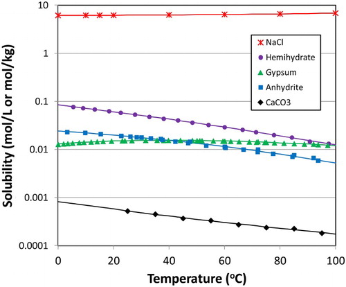
(e) shows the resulting pore-water anion concentration profiles from this analysis for crystalline host rock. Whereas the halite will fully dissolve during initial HCB preparation, the amounts of gypsum and calcite will exceed their respective solubility limits. Thus, the initial pore-water composition is predicted to be 0.03 mol L−1 Cl−, 0.014 mol L−1 , and 0.00068 mol L−1 HCO3–. As the surface temperature increases and the HCB dries out, the pore water [Cl−] will increase. Meanwhile, the concentrations of
and HCO3− will decrease due to the retrograde solubility behaviour shown in . After reaching a peak concentration of 0.066 mol L−1, the pore water [Cl−] will decrease as the buffer re-saturates. Finally, the [Cl−] will increase as the buffer reaches equilibrium with the saline ground water.
Thus, Cl− is predicted to be the predominant anion in the pore water at all times, with at least a two-fold excess over . Chloride is beneficial for the corrosion behaviour of copper containers because it promotes uniform corrosion rather than localised corrosion or stress corrosion cracking [Citation26]. If necessary, the initial pore-water Cl− concentration could be further increased by instead using saline water to wet the bentonite for compaction. Note that a longer-term prediction of the pore-water composition than what is shown in (e) would require a more-sophisticated analysis than that conducted here.
Evolution of the DGR to the long-term anoxic phase
Eventually, all of the initially trapped O2 (and Cu(II) produced by oxidation of Cu(I) by O2) will have been consumed and the γ-radiation field will have decayed such that corrosion of the container can only occur if sulphide is present in the repository. Although microbial activity will be suppressed within the bentonite itself, sulphide could be produced by sulphate-reducing bacteria in regions of the repository where microbial activity is not suppressed by low aW; for example, in the host rock or at the rock HCB interface [Citation27,Citation28].
(f) shows the predicted time dependence of the interfacial flux of HS− for various locations on the container surface in a Canadian DGR placement room [Citation29]. A constant HS− concentration of 10−6 mol L−1 has been assumed to be present at the wall of the placement room for these mass-transfer simulations. There are several important features of the sulphide flux profiles in (f). First, significant amounts of HS− do not reach any part of the container surface until several years after sulphide production starts. Thus, based on the O2 profiles in (d), it is not expected that a sulphide film will exist on the container whilst O2 is present, and thus there are no concerns about the catalysis of the O2 reduction reaction by Cu2S [Citation30,Citation31]. Second, the supply of HS− is different for different parts of the container surface. For geometrical reasons, the maximum flux is to the hemispherical end caps, whereas the ‘interior’ surfaces shielded from the source of sulphide by the surrounding container surfaces experience the lowest flux. The ‘exterior’ surfaces of the containers closest to the source of sulphide are subject to an intermediate flux. Third, the HS− fluxes are small. For example, an interfacial HS− flux of 10−6 mol m−2 a−1 is equivalent to a corrosion rate of just 0.01 nm a−1.
Impact of environmental evolution on corrosion behaviour
Although the duration of each stage will depend on the host rock properties (especially for crystalline vs. sedimentary host rock), the evolving environment may be described by four general stages: (i) immediate post-placement, (ii) dry-out, (iii) container re-wetting and buffer saturation, and (iv) long-term anoxic.
Stage 1: immediate post-placement period
Immediately after emplacement in the DGR, there may be sufficient moisture to support aqueous corrosion. The environment will be aerobic and the γ-radiation dose rate will be at its highest level. Stage 1 will extend from the time of placement to a few days or months, depending upon the rate at which the thermal gradient drives away the moisture in the HCB or oxygen is consumed by corrosion or other processes.
Stage 2: dry-out period
Eventually, the container surface will dry out sufficiently that aqueous corrosion ceases. The duration of this stage will depend on the initial HCB moisture content, the magnitude of the thermal gradient, and the hydraulic properties of the host rock. For illustrative purposes, we have estimated periods of up to a few years for crystalline host rock ((b)) and a few hundred years for sedimentary rock ((c)), but the actual duration of Stage 2 will be design- and site-specific.
Stage 3: container re-wetting and saturation of buffer
Stage 3 is characterised by the transition from a dry to a saturated near-field environment, and consumption of residual oxygen. The progressive deliquescence of salt contaminants as the near-field RH increases may result in non-uniform wetting of the container surface and, if oxidants are still present, spatial separation of anodic and cathodic reactions and the possibility of localised corrosion.
Stage 4: long-term anoxic phase
Stage 4 begins once the near-field reaches full saturation. The long-term near-field environment will be characterised by the continued cooling ((a)) and by anoxic conditions. There is no evidence in Canada for the injection of dilute and possibly aerated, glacial meltwaters to repository depth so issues associated with buffer erosion are extremely improbable. The steady production of HS− at the repository boundaries, maintained by ongoing microbial activity, will be the dominant source of corrosion during this stage.
Conclusions
The corrosion behaviour of used fuel waste containers in a bentonite-backfilled DGR will depend on the near-field environmental conditions, which can differ significantly from those in the host rock, especially during the early thermal-saturation transient. This work defines the expected time dependence of various environmental parameters in four general stages: (i) immediate post-placement, (ii) dry out, (iii) container re-wetting and buffer saturation, and (iv) long-term anoxic. Future work is encouraged to consider these stages in more detail and to more thoroughly assess the implications for container corrosion.
Disclosure statement
No potential conflict of interest was reported by the authors.
ORCID
David S. Hall http://orcid.org/0000-0001-9632-0399
Peter G. Keech http://orcid.org/0000-0001-8435-628X
References
- Qin Z, Deljeet R, Ai M, et al. Corros Eng Sci Technol. ( this volume).
- Cuevas J, Villar MV, Fernandez AM, et al. Pore waters extracted from compacted bentonite subjected to simultaneous heating and hydration. Appl Geochem. 1997;12:473–481. doi: 10.1016/S0883-2927(97)00024-3
- Gómez-Espina R, Villar MV. Geochemical and mineralogical changes in compacted MX-80 bentonite submitted to heat and water gradients. Appl Clay Sci. 2010;47:400–408. doi: 10.1016/j.clay.2009.12.004
- Villar MV, Fernández AM, Gómez R, et al. State of a bentonite barrier after 8 years of heating and hydration in the laboratory. Mat. Res. Soc. Symp. Proc. 985, paper 0985-NN11-19; 2007.
- Karnland O, Olsson S, Dueck A, et al. Long term test of buffer material at the Äspö Hard Rock Laboratory, LOT project. Final report on the A2 test parcel. Swedish Nuclear Fuel Supply Company Report, SKB-TR-09-29; 2009.
- Åkesson M. Temperature buffer test. Final report, Swedish Nuclear Fuel and Waste Management Company Report, TR-12-04; 2012.
- Porewater extraction from argillaceous rocks for geochemical characterisation. Nuclear Energy Agency Report, ISBN 92-64-17171-9; 2000.
- Wersin P. Geochemical modelling of bentonite porewater in high-level waste repositories. J Contam Hydrol. 2003;61:405–422. doi: 10.1016/S0169-7722(02)00119-5
- Bradbury MH, Baeyens B. Porewater chemistry in compacted re-saturated MX-80 bentonite. J Contam Hydrol. 2003;61:329–338. doi: 10.1016/S0169-7722(02)00125-0
- Birgesson M, Karnland O. Ion equilibrium between montmorillonite interlayer space and an external solution—Consequences for diffusional transport. Geochim Cosmochim Acta. 2009;73:1908–1923. doi: 10.1016/j.gca.2008.11.027
- Samper J, Zheng L, Montenegro L, et al. Coupled thermo-hydro-chemical models of compacted bentonite after FEBEX in situ test. Appl Geochem. 2008;23:1186–1201. doi: 10.1016/j.apgeochem.2007.11.010
- Sena C, Salas J, Arcos D. Thermo-hydro-geochemical modelling of the bentonite buffer. LOT A2 experiment. Swedish Nuclear Fuel and Waste Management Company Report, SKB TR 10-65; 2010.
- King F, Lilja C, Pedersen K, et al. An update of the state-of-the-art report on the corrosion of copper under expected conditions in a deep geologic repository. Swedish Nuclear Fuel Supply Company Report, SKB-TR-10-67; 2010.
- Guo R. Thermal response of a Mark II conceptual deep geological repository in crystalline rock. Nuclear Waste Management Organization Technical Report, NWMO TR-2016-03; 2016.
- Cole IS. Atmospheric corrosion. In: RA Cottis, MJ Graham, R Lindsay, SB Lyon, JA Richardson, JD Scantlebury, FH Stott, editors. Shreir’s corrosion, Volume 2, Chap 2.16. Amsterdam: Academic Press; 2010. p. 1051–1093.
- Man A, Martino JB. Thermal, hydraulic and mechanical properties of sealing materials. Nuclear Waste Management Organization Report, NWMO TR–2009-20; 2009.
- King F, Kolar M, Shoesmith, DW. Modelling the effects of porous and semi-permeable layers on corrosion processes. CORROSION/96, NACE International, Houston, TX, paper no. 380; 1996.
- Collin M, Rasmuson A. A comparison of gas diffusivity models for unsaturated porous media. Soil Sci Soc Am J. 1988;52:1559–1565. doi: 10.2136/sssaj1988.03615995005200060007x
- Weerts AH, Freijer JI, Bouten W. Modeling the gas diffusion coefficient in analogy to electrical conductivity using a capillary model. Soil Sci Soc Am J. 2000;64:527–532. doi: 10.2136/sssaj2000.642527x
- King F, Kolar, M. A numerical model for the corrosion of copper nuclear fuel waste containers. Mats. Res. Soc. Symp. Proc. 412, Materials Research Society, Pittsburgh, PA; 1996. p. 555–562.
- Wersin P, Spahiu K, Bruno J. Time evolution of dissolved oxygen and redox conditions in a HLW repository. Swedish Nuclear Fuel Supply Company Report, SKB-T9406-02; 1994.
- Müller, HR, Garitte B, Vogt T, et al. Implementation of the full-scale emplacement (FE) experiment at the Mont Terri rock laboratory. Swiss J Geosci. doi:10.1007/s00015-016-0251-2.
- Marco RP, Joseph JM, Hall DS, et al. Corros Eng Sci Technol. ( this volume).
- Cong H, Michels HT, Scully JR. Passivity and pit stability behavior of copper as a function of selected water chemistry variables. J Electrochem Soc. 2009;156:C16–C27. doi: 10.1149/1.2999351
- Karnland O, Olsson S, Nilsson U. Mineralogy and sealing properties of various bentonites and smectite-rich clay minerals. Swedish Nuclear Fuel Supply Company Report, SKB-TR-06-30; 2006.
- King F, Newman RC. Stress corrosion cracking of copper canisters. Swedish Nuclear Fuel Supply Company Report, SKB TR-10-04; 2010.
- King F. Microbiologically influenced corrosion of nuclear waste containers. Corrosion. 2009;65:233–251. doi: 10.5006/1.3319131
- Stroes-Gascoyne S, Hamon CJ, Maak P, et al. The effects of the physical properties of highly compacted smectitic clay (bentonite) on the culturability of indigenous microorganisms. Appl Clay Sci. 2010;47:155–162. doi: 10.1016/j.clay.2008.06.010
- Briggs S, McKelvie J, Keech P, et al. Corros Eng Sci Technol. ( this volume).
- Scully JR, Edwards ME. Review of the NWMO copper corrosion allowance. Nuclear Waste Management Organization Report, NWMO TR–2013-04; 2013.
- King F, Chen J, Qin Z, et al. Corros Eng Sci Technol. ( this volume).