Abstract
We study the relationship between the geometry of a point defect and the spatial distribution of the strain energy in an otherwise regular two-dimensional cellular solid. Sites of concentrated strain energy are potential sites for failure initiation in the cellular solid. For simplicity, a hexagonal honeycomb structure is chosen for our analysis. In our description, the basic building block of the honeycomb is not a beam, but rather a three-armed “joint”, with the three beams meeting at a junction point. A minimal defect is introduced in an otherwise regular hexagonal honeycomb by exchanging one joint of the regular honeycomb with a joint of varying geometry. Finite element methods and micromechanical models are used to calculate the spatial distribution of the strain energy density (SED). Two different scenarios are found depending on the external loading. For hydrostatic loading, the SED is concentrated in the defect. Uniaxial loading resulted in intricate distribution of the SED, with its highest values not in the defect but in the nearer environment of the defect. The study demonstrates the complexity of SED patterns occurring around defects, which change their characteristics depending on the loading conditions.
1. Introduction
The nature of interactions between physical entities results very often in their periodic arrangement. Examples exist over very different length scales from atomic crystal lattices Citation1 to mesoscopic materials created by self-assembly Citation2 to macroscopic periodic structures Citation3. Despite their periodicity, these arrangements are never free of defects. The interest in these defects originates from their crucial influence on the macroscopic properties of the material. For instance, the physics of defects in crystalline solids, in particular point defects in the form of impurities, has been studied intensively to understand their influence on strength and plastic behaviour Citation4.
On a much larger length scale, periodic cellular solids have recently become a popular research topic Citation3,Citation19–24. Cellular solids, in particular 2D honeycombs and 3D foams, are widely used technologically in lightweight constructions. In addition, cellular solids, both regular and random, are abundant in nature Citation9 with the sponge-like trabecular bone Citation10,Citation11, the anisotropic cellular structure found in wood Citation12,Citation13 and cork Citation14,Citation15, and the glass sponge Euplectella Citation16 being only some of many examples studied. Their application both in nature and technology is based on the idea to use a minimal amount of material to create strong reinforcing structures. Again, the impossibility of defect-free periodic cellular solids raises questions about the influence of defects on macroscopic mechanical performance. Intensive finite element analysis has been performed to understand the influence of non-periodic microstructures Citation17,Citation18 and different types of morphological imperfections, such as missing cell walls, cell-wall waviness, misalignment and thickness, on elastic modulus, strength Citation19–24 and toughness Citation25.
Here, we present work that focuses on the influence of a defect on its local environment within the cellular solid. In particular, we investigate how a defect, in the form of a structural perturbation, can result in concentrations of the elastic strain energy when a cellular solid is deformed. Concentrations of the strain energy indicate regions in the cellular architecture where brittle failure could initiate. Our research is motivated by the question as to whether these sites with high strain energy values can be predicted from a geometrical analysis of the cellular structure. Considering trabecular bone, this is extremely relevant in assessing the quality of bone architecture in osteoporotic patients Citation26. Recent experimental advances in imaging trabecular bone using micro-computed tomography Citation27 raise hopes that, based on structural analysis, “weak points” in the bone structure can be identified, which could then act as initiators of (non-traumatic) bone fractures. Finite element studies investigating the distribution of forces in cellular solids have demonstrated that the width of the force distribution depends critically on the degree of randomness of the structure, with increasing randomness resulting in a broader distribution Citation28. In Voronoi honeycombs, the axial strains in the cell walls have been found to be approximately normally distributed Citation19. Luxner et al. Citation29 studied how the energy is distributed in different struts of a 3D open cell structure when loaded uniaxially by looking at frequency distributions of the energy. In cases of a small irregularity of the structure, the distribution was sharply peaked, indicating a concentration of the strain energy in few sites of the cellular solid Citation29.
To investigate the effect of a structural defect on its environment, our strategy is to study a model system of reduced complexity. A single defect is introduced in a two-dimensional regular honeycomb structure. A regular honeycomb is a well-studied system Citation3,Citation30,Citation31, which is mechanically isotropic and has relevance both in biology Citation12,Citation32 and engineering. In this regular honeycomb, a minimal structural defect is introduced. For a defect to carry geometrical information, it has to contain at least several struts that meet in a junction point. For honeycombs, joints have a coordination number of three (). For this work, the issue is to consider the cellular structure as a periodic assembly of joints, the same way a crystalline lattice is built up periodically by atoms. The single defect then plays the role of an impurity in an otherwise regular honeycomb. The aim is to classify defects in terms of their ability to concentrate the strain energy density. As a tool for classification, we mechanically characterise the periodic irregular lattice honeycomb, which can be constructed in a unique way of identical copies of the defect joint. It is shown that a mechanically disadvantageous geometry of the defect does not necessarily lead to a concentration of the strain energy density in the defect, but to a concentration in its neighbouring environment.
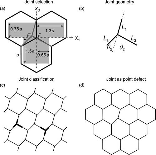
Figure 1. Procedure to generate different joint defects and investigate their mechanical behaviour under two different scenarios. (a) Three cells of a regular hexagonal honeycomb, where a single joint in the centre is perturbed by shifting the position of its junction point, P, inside a given T-shaped region (gray area). The size of this region is given in terms of the lattice dimension, a. The rectangular shape of this region is chosen for convenience. (b) The geometry of a joint characterized generally by eight geometrical parameters. (c) Periodic irregular honeycomb lattice built up in a unique way by identical copies of the joint of . (d) The joint is introduced as a defect in an otherwise regular hexagonal honeycomb.
2. Methods
The influence of different joint defects on their environment in an otherwise regular hexagonal honeycomb is investigated using a three-step approach. First, appropriate joints are selected using the restriction that the joint should fit as a defect into a regular honeycomb lattice, which strongly decreases the parameter space of possible joints. Second, the joint is mechanically characterised by constructing a periodic lattice in a unique way with the joint as a basic building block using analytical results from Overaker et al. Citation33. In the last step, the joint is introduced as a defect in the regular honeycomb lattice, and its performance and the influence on its environment under mechanical loading is studied using finite element modelling. The steps of this procedure are shown in and are explained in more detail below.
2.1. Selection of joint
For general two-dimensional honeycombs, which have a coordination number z = 3, a joint consists of three beams, which meet each other at a junction point (). Assuming cylindrical beams of circular cross-section, a joint is geometrically characterised by eight parameters: three beam lengths, three cross-sectional radii and two angles. In the following, the radii of the three struts forming the joint are assumed to be identical. The number of independent parameters is further reduced when the selection of joints is restricted to joints that can be inserted in a regular honeycomb to act as a defect. In this case, the joint is fully characterised by the coordinates of the junction point, P = (x 1, x 2), where the origin of the coordinate system (x 1, x 2) is conveniently chosen to be the junction point of a regular joint (). Selection of the junction point, P, within a T-shaped area defined in excludes only extreme joint geometries of minor interest.
2.2. Classification of the joint (periodic irregular honeycomb)
To assess the mechanical performance of a joint, the joint is used to construct in a unique way a periodic irregular honeycomb lattice (). The beams are modelled as Euler–Bernoulli beams with circular cross-section of radius, r, and isotropic material properties with a uniform Young's modulus, E, and Poisson ratio, ν. The full elastic matrix, Cij , of the honeycomb structure can then be derived analytically as a function of the joint geometry and material properties Citation33, where Hooke's law in Voigt notation reads as σi = Cijεj . With Cij given as analytical functions of the coordinates of the junction point, P = (x 1, x 2), and applying a stress, σi , mechanical quantities, such as the strain of the joint inside the periodic lattice, εj , or the joint strain energy density (SED), U = Cijεiεj /2V joint can be calculated. V joint denotes the material volume corresponding to the joint with junction point P = (x 1, x 2), given by
Constructed in this way, the different periodic honeycombs have, in addition to different geometries, also different relative densities, i.e. material volume per total volume. To exclude the influence of the relative density, the beam lengths of the joints are uniformly rescaled to result in the same relative density defined by the relative density of the regular hexagonal honeycomb. The different periodic lattices are characterised according to three loading conditions: compressive load along the horizontal x 1 direction, compressive load along the vertical x 2 direction and hydrostatic compression.
2.3. Effect of joint acting as a defect in a regular honeycomb
In the final step, the joint, defined and characterised in the previous section, is implanted as a defect in a regular hexagonal honeycomb (). The linear elastic mechanical problem under different loading conditions (hydrostatic compression, uniaxial compression) is solved numerically using the finite element method (FEM) (ABAQUS version 6.6; Rising Sun Mills, Providence, RI, USA). Each half-beam of the joint is modelled as a Timoshenko beam Citation34,Citation35 with a lattice size of a = 1 cm, a radius r 0 = 0.005a, Young's modulus E = 10 GPa and Poisson ratio ν = 0.3. The high slenderness ratio of the beams were chosen to reduce the influence of transverse shear, which was neglected in the analytical solutions using Euler–Bernoulli beams to characterise the joints. Periodic boundary conditions for the displacement field were used Citation21 for a system of honeycombs with a linear system size of 105a, which corresponds to 8608 joints overall. The system size was large enough to avoid interactions of the defect with itself due to the periodic boundary conditions, as tested with lattices of different size. Nevertheless, for the calculation of the total strain energy density of the lattice, only the inner half of the lattice was considered for the evaluation, since the periodic boundary conditions lead to distortions of the strain and stress fields at the boundaries Citation21. Results shown here are restricted to the case that the joint has left-right symmetry, i.e. the junction point of the joint is defined as P(0, x 2). In addition to the implantation of geometrical defects as described above, the effect of a second kind of defect was tested. Here, the geometry of the regular honeycomb remained untouched, but the cross-sectional radius r of the beams of one joint (and its connection to the rest of the lattice) was changed. Such a “mass defect” is characterised by the parameter k = r/r 0. Values of k in the range 0.01–100 were studied.
3. Results
3.1. Classification of the joint (periodic irregular honeycomb)
shows the strain energy density (SED) of periodic irregular honeycombs, which were generated starting from a joint with the procedure explained above (). According to this procedure, each coloured point in the contour plots of (top), represents the SED of a periodic honeycomb with different geometry, but the same relative density. The SED is normalised by the corresponding energy density of a regular honeycomb, SED0, under the same external loading conditions. For symmetry reasons, only half of the T-shaped area of is shown. For a given loading condition, joints are classified as “soft” or “stiff”, where soft (stiff) joints are the sites of high (low) SED values. Note the very different lattice geometries, which are obtained by choosing the junction point P along the right-left axis of symmetry, i.e. P(0, x 2) (, bottom).
Figure 2. Contour plots of the strain energy density (SED) for different irregular periodic honeycombs, renormalised to have the same relative density, under uniaxial horizontal (a), vertical (b) and hydrostatic (c) compression. Each coloured pixel in the plot represents a honeycomb of different geometry as defined in the text and . The SED is normalised by the energy density of the regular hexagonal honeycomb, SED0.
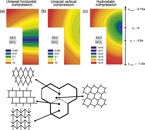
By compressing a periodic honeycomb lattice along the horizontal x 1 direction, the minimum SED is obtained when the x 2 coordinate of the junction point of the joint equals −0.5a (). In this case, where the honeycomb resembles a brick wall (, bottom), beams of the joint align along the loading direction and the corresponding SED is three orders of magnitude less than the one stored in the regular lattice (SED0). Already small deviations from this particular “brick wall” geometry result in significant drops in the SED. For a compressive load in the vertical x 2 direction, the stiffest honeycomb is not the regular isotropic one, but a lattice obtained when the junction point is moved along the vertical direction of about −0.2a (). The shallow colour gradient within the plot indicates that, under this loading condition, honeycombs are rather insensitive to the specific geometry of the honeycomb. In contrast, hydrostatic compression results in the strongest variations of the SED to over five orders of magnitude (). The stiffest geometry is realised by a regular joint, P = (0, 0), resulting in an isotropic regular honeycomb.
3.2. Effect of joint acting as a defect in a regular honeycomb
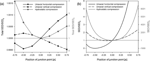
The exchange of one joint in a regular honeycomb with a joint of different geometry leads to a redistribution of the SED, which is naturally homogeneous for the regular honeycomb. Firstly, we investigate the problem of whether a joint, which was classified as soft or stiff (in the previous section), results in a softening or stiffening of the global lattice. The total strain energy density of the global lattice for the three loading cases as a function of the joint geometry is plotted () and compared with the strain energy density of the periodic irregular lattice (). Since only symmetrical joints are considered, the x 2-coordinate of the junction point suffices to identify different joints and is plotted on the x-axis. For hydrostatic compression (full grey line), there is a qualitative agreement between the two cases: a locally soft joint () weakens the lattice also at the global level (). For uniaxial horizontal compression (full black line), the minimum in both lattices is shifted at −0.5a and around that position the behaviour is also similar. For uniaxial vertical compression (dashed line), however, joints, classified as soft, do not soften the overall lattice for positive values of the junction point position (, right part of the plot).
Figure 3. Total strain energy density of the regular honeycomb with defect (a) and the irregular periodic honeycomb (b) constructed with the defect joint following the procedure of . The x 2 coordinate of the junction point of the joint suffices to characterise the defect (plotted on the x-axis), since only joints with left-right-symmetry are considered. The three different loading cases of uniaxial horizontal, uniaxial vertical and hydrostatic compression are shown with full, dashed and full grey lines, respectively.
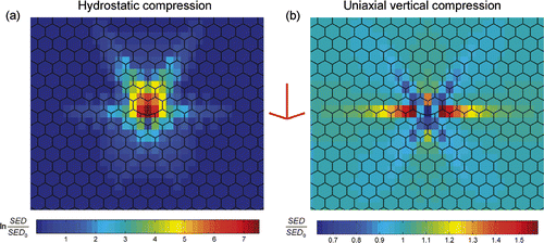
A plot of the spatial distribution of the SED allows one to study the redistribution of the SED due to the inclusion of a defect. A representative case of an arrow-shaped geometrical defect, which is characterised by a junction point P = (0, −0.75a) is shown in . The SED has its peak value in the defect when the honeycomb is compressed hydrostatically (). The energy is strongly concentrated in the defect with a SED value more than seven orders of magnitude larger than the far field value. Although not well presented by the logarithmic scaling of , the SED returns very rapidly to its far-field value when moving away from the defect. The breaking of the up–down symmetry by the defect is clearly reflected in the asymmetric SED pattern. Under uniaxial vertical compression (), the resulting SED pattern shows pronounced long-ranged anisotropy. The SED is concentrated in the joints, which form the horizontal extension of the defect. Values increased more than 10% in comparison with the far field value are found up to the ninth nearest neighbour. Stripes of reduced SED are found in the remaining four directions of the six-fold symmetry. The largest SED values of about 1.6 SED0 are found in the second nearest neighbour joints of the defect. In the defect itself, the SED is reduced to approximately 0.5 SED0.
Figure 4. Spatial pattern of the strain energy density around a central defect in a regular hexagonal honeycomb under hydrostatic (a) and uniaxial vertical (b) compression. The arrow-shaped joint creating the defect is sketched between the two plots. The colour of each rectangular patch corresponds to the SED absorbed in that particular joint. Only a sub-region of the simulated lattice around the defect is shown. Again, the SED is normalised by the value for the regular honeycomb, SED0, which corresponds approximately to the energy density of joints far away from the defect.
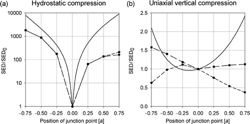
While shows the detail of the SED pattern for a specific case, summarizes the results for all symmetric joints and compares the outcome with the SED obtained from the joint classification (full line) (see beginning of Section 3; ). Two pieces of information are given in : the SED of the defect joint (circles, and short dashed line) and the peak values of the SED (squares, and long dashed line), which can occur in the defect itself or in one of the surrounding joints of the regular honeycomb. Under hydrostatic load, joint classification predicts, at least qualitatively, their behaviour as a defect (). The softer the joint was classified (full line), the higher the values of the SED calculated from FE in the defect joint. Since for defects with junction points in the range (−0.75a, 0.5a) peak values of the SED occur in the defect, circles and squares are superimposed for this case. Under uniaxial vertical compression, the situation is reversed (). Joints that have been classified as soft, display the lowest value of the SED when acting as a defect. The corresponding SED peak values show the opposite behaviour to the SED of the defect, being high when the SED in the defect is low.
Figure 5. Strain energy density (SED) of the defect joint (circles) within a regular honeycomb under hydrostatic (a) and uniaxial (b) compression. The x 2 coordinate of the junction point of the joint suffices to characterise the defect (plotted on the x-axis), since only joints with left-right symmetry are considered. The SED of the defect joint is compared with the maximum value of the SED within the lattice (squares) and the analytical result of the SED for the irregular periodic honeycomb constructed with the defect joint (full line).
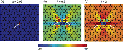
When a mass defect is introduced, i.e. the beams in one joint have reduced or increased cross-sectional radii without perturbing the regular geometry of the honeycomb, the resulting SED pattern is even qualitatively very different depending on the amount of joint mass reduction (). In particular, the maximum value of the SED is found in different positions with respect to the position of the defect. For very low mass of the defect (approximately k ≤ 0.07), the maximum of the SED occurs at the location of the defect itself (). For less severe reductions (0.07 < k < 1), the highest strain energy is observed at the third nearest neighbour joints of the defect located on the inclined symmetry directions of the honeycomb (). When the defect presents beams which are thicker than the regular joint (k > 1), the maximum value of the SED is found in the fourth neighbours situated on a horizontal line passing thorough the defect (). In all cases, the six-fold symmetry of the honeycomb is reflected in an anisotropic long-ranged SED pattern.
Figure 6. Spatial pattern of the strain energy density (SED) around a central defect in a regular hexagonal honeycomb under uniaxial vertical compression. The defect joint has unchanged geometry with respect to the regular honeycomb, but its beams have a cross-sectional radius changed by a factor k. Three different such mass defects are plotted corresponding to a very thin (a), a thin (b) and a thick defect joint (c) compared to the dimensions of the other beams. White arrows indicate the sites of maximum SED.
4. Discussion
In this paper, we combined analytical and numerical results to understand how the individual building blocks of a 2D cellular structure behave as defects. As elementary building blocks, we introduced joints, which are the smallest entities in a cellular solid carrying geometrical information. They can be interpreted as analogous to atoms in crystalline lattices. The individual mechanical behaviour of a joint, in terms of classification as stiff and soft, was determined by constructing in a unique way an irregular periodic honeycomb using only identical copies of the joint. To test then the joint behaviour as a defect, we chose the simplest possible situation, i.e. to implement the joint as a defect in an isotropic regular honeycomb. For quantification of local mechanical performance, the strain energy density (SED) as a simple scalar quantity was reported, but qualitatively identical results were obtained by looking at the maximal strain or stress.
The classification of joints in , based on analytical solutions of the mechanical problem, presents known results in a new compact form. The stiffest joints for a given loading situation are those that minimise bending, so that most of the deformation occurs by axial compression of the beams. For hydrostatic compression (), the regular lattice is characterised by pure axial deformations with the result that the elastic properties scale linearly with the relative density Citation3. Even small deviations from the regular geometry introduce bending and, therefore, a significant increase in the amount of energy absorbed. Under uniaxial horizontal compression (), a brick-wall like architecture, corresponding to a junction point of P = (0, −0.5a) also avoids bending in the small deformation limit. Also, the minimum of SED around P = (0, −0.2a) for uniaxial vertical compression () can be understood in terms of simple beam bending. Since the bending moment acting on one of the lower beams, L 2 or equivalently L 3, is proportional to L 2 sin θ 2, a minimisation of it under the condition that the relative density of the resulting honeycomb is equal to the regular one, leads to a minimum at around P = (0, −0.2a).
The insertion of a joint with given geometry as a defect in an otherwise regular honeycomb leads to intricate spatial distributions of the SED ( and ). Under vertical uniaxial loading, the SED pattern displayed a hexagonal symmetry of long range. Joints of high values of the SED are either on the horizontal extension of the defect position or on lines at 60° and 120° relative to the horizontal line. The answer to the question of whether “individual” joint behaviour is reflected in its behaviour as a defect depends crucially on loading conditions. For hydrostatic compression, joints which were classified as soft, behaved also as a weak defect in the regular honeycomb by concentrating the SED within themselves. Under uniaxial compression, however, the situation was reversed, so that soft joints were so effective in shielding the loading from themselves, that SED values were very low in the defect itself, but highly increased in the neighbourhood of the defect. In the context of failure of a cellular solid, such as trabecular bone, this implies that sites with a mechanically unfavourable geometry do not necessarily break first, but initiation of failure can be shifted to their nearer neighbourhood. Even in the situation where the geometry of the regular hexagonal honeycomb is unchanged and only one joint is thinned or thickened, the question of where the SED is concentrated cannot be stated simply. For very thin defects, the concentration of the SED within the defect results from the low volume of the defect, which decreases faster than the strain energy in the defect. For moderately thin defects, the strain energy density is not concentrated in the defect itself.
In conclusion, this paper has investigated the effect of defect geometry on the spatial distribution of the strain energy density around the defect within a regular two-dimensional cellular solid. This work is only a first step, focussing on simple defects within a 2D hexagonal honeycomb. Further investigations have to show whether our results are only specific to honeycombs or apply also to other lattices in two and three dimensions. Materials do not just contain single defects and it is likely that a more complex mechanical response would come from the interaction between defects, something that remains to be investigated. Such work could also have interesting implications for the understanding of the mechanics of bone remodeling. In the renewal process, small bone packets are resorbed and deposited on the bone surface. Bone remodelling is thought to be mechanically controlled, allowing the trabecular bone architecture to adapt to a changing mechanical environment Citation36,Citation37. Basic control of this process is believed to be that removal of material increases the local loading and leads to repair. Our results question whether such a feedback is a general property of cellular solids or depends on the specific architecture.
Acknowledgement
DR was supported by the EU Marie Curie EST Program on Biomimetic Systems, MEST-CT-2004-504465.
References
- Pozrikidis , C . 2008 . Int. J. Solids Struct. , 45 : 732
- Bishop , KJM , Wilmer , CE , Soh , S and Grzybowski , BA . 2009 . Small , 5 : 1600
- Gibson , LJ and Ashby , MF . 1997 . Cellular Solids: Structure and Properties , Cambridge : Cambridge University Press .
- Haasen , P . 1996 . Physical Metallurgy , New York : Cambridge University Press .
- Evans , AG , Hutchinson , JW and Ashby , MF . 1998 . Prog. Mater. Sci. , 43 : 171
- Evans , AG , Hutchinson , JW , Fleck , NA , Ashby , MF and Wadley , HNG . 2001 . Prog. Mater. Sci. , 46 : 309
- Zok , FW , Rathbun , HJ , Wei , Z and Evans , AG . 2003 . Int. J. Solids Struct. , 40 : 5707
- Wadley , HNG , Fleck , NA and Evans , AG . 2003 . Comp. Sci. Tech. , 63 : 2331
- Wegst , U and Ashby , M . 2004 . Phil. Mag. , 84 : 2167
- Keaveny , TM , Morgan , EF , Niebur , GL and Yeh , OC . 2001 . Annu. Rev. Biomed. Eng. , 3 : 307
- Fratzl , P and Weinkamer , R . 2007 . Prog. Mater. Sci. , 52 : 1263
- Gibson , LJ . 2005 . J. Biomech. , 38 : 377
- Easterling , KE , Harrysson , R , Gibson , LJ and Ashby , MF . 1982 . Proc. R. Soc. Lond. Ser. A , 383 : 31
- Rosa , ME . 2008 . Phil. Mag. Lett. , 88 : 637
- Gibson , LJ , Easterling , KE and Ashby , MF . 1981 . Proc. R. Soc. Lond. Ser. A , 377 : 99
- Aizenberg , J , Weaver , JC , Thanawala , MS , Sundar , VC , Morse , DE and Fratzl , P . 2005 . Science , 309 : 275
- Fazekas , A , Dendievel , R , Salvo , L and Bréchet , Y . 2002 . Int. J. Mech. Sci. , 44 : 2047
- Zhu , HX , Hobdell , JR and Windle , AH . 2000 . Acta Mater. , 48 : 4893
- Silva , MJ and Gibson , LJ . 1997 . Int. J. Mech. Sci. , 39 : 549
- Guo , XE and Gibson , LJ . 1999 . Int. J. Mech. Sci. , 41 : 85
- Chen , C , Lu , TJ and Fleck , NA . 2001 . Int. J. Mech. Sci. , 43 : 487
- Chen , C , Lu , TJ and Fleck , NA . 1999 . J. Mech. Phys. Solids , 47 : 2235
- Fortes , MA and Ashby , M . 1999 . Acta Mater. , 47 : 3469
- Chen , DH and Ozaki , S . 2009 . Comp. Struct. , 89 : 52
- Romijn , NER and Fleck , NA . 2007 . J. Mech. Phys. Solids , 55 : 2538
- Gunaratne , GH , Rajapaksa , CS , Bassler , KE , Mohanty , KK and Wimalawansa , SJ . 2002 . Phys. Rev. Lett. , 88 : 068101
- Nazarian , A and Müller , R . 2004 . J. Biomech. , 37 : 55
- Ngan , AHW . 2005 . Proc. R. Soc. Lond. Ser. A , 461 : 433
- Luxner , MH , Stampfl , J and Pettermann , HE . 2007 . Int. J. Solids Struct. , 44 : 2990
- Warren , WE and Kraynik , AM . 1987 . Mech. Mater. , 6 : 27
- Masters , IG and Evans , KE . 1996 . Comp. Struct. , 35 : 403
- Raabe , D , Sachs , C and Romano , P . 2005 . Acta Mater. , 53 : 4281
- Overaker , DW , Cuitino , AM and Langrana , NA . 1998 . J. Appl. Mech. Trans. ASME , 65 : 748
- Silva , MJ , Hayes , WC and Gibson , LJ . 1995 . Int. J. Mech. Sci. , 37 : 1161
- Onck , PR , Andrews , EW and Gibson , LJ . 2001 . Int. J. Mech. Sci. , 43 : 681
- Dunlop , JWC , Hartmann , MA , Brechet , YJ , Fratzl , P and Weinkamer , R . 2009 . Calcif. Tiss. Int. , 85 : 45
- Huiskes , R , Ruimerman , R , van Lenthe , GH and Janssen , JD . 2000 . Nature , 405 : 704