Abstract
In the present paper, a thermomechanically coupled hyperelastic-plastic model is set up to predict the yield stress of polysynthetically twinned TiAl crystals as a function of temperature, load angle, content, lamellar thickness and domain size. The elastic deformation is modelled in terms of the Helmholtz free energy density, and the deformation in the plastic regime is mapped by crystal plasticity theory. The yield stress temperature anomaly of intermetallics is incorporated in the model via the critical resolved shear stresses. The numerical results show a very good agreement with experimental results for a wide range of microstructural parameters and temperatures.
1. Introduction
The growing demand for lightweight construction in several industrial branches strongly promotes research on promising materials such as the intermetallic compound TiAl. TiAl alloys are potential materials for a wide range of high-temperature lightweight applications in aeronautical as well as in automotive and energy sectors [Citation1,Citation2]. Due to their remarkable thermomechanical properties [Citation3,Citation4], they are – under suitable operating conditions – capable of replacing conventional high-temperature materials as lately observed in turbocharger wheels and turbine blades [Citation1,Citation5].
The superior thermomechnical properties of TiAl alloys are closely related to their composition and respective microstructure. Following [Citation6], TiAl alloys can be differentiated into four possible microstructures: near-gamma, duplex, nearly lamellar and fully lamellar. The fully lamellar microstructure has experimentally been identified by many authors to exhibit the highest creep resistance which is a key feature for the respective applications.
Figure 1. SEM image of fully lamellar microstructure Ti-42Al-8.5Nb (picture courtesy of M. Rackel, Helmholtz-Zentrum Geesthacht).
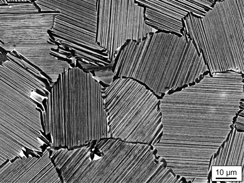
The fully lamellar microstructure shown in Figure is composed of two constituent phases (
Al) and
(TiAl), where
is the minority phase. These phases are arranged in parallel lamellae with a thickness of a few 10 nm up to some
m depending on composition and processing (see e.g. [Citation7,Citation8]). One set of parallel lamellae forms a so-called colony, usually with a diameter ranging between 20
m and 1000
m.
Since the micromechanical behaviour of single lamellar colonies determines the behaviour of the bulk material, various authors conducted experiments with specimens made of a single set of lamellae, often referred to as polysynthetically twinned crystal, e.g. [Citation9–Citation16]. These experiments revealed a strong plastic anisotropy of the lamellar compound, i.e. a dependence of yield strength and creep resistance on the load angle with respect to the lamellar plane.
The deformation of polysynthetically twinned crystals is best described via crystal plasticity in combination with a finite element analysis. Due to the small thickness of the lamellae and their high aspect ratio, the balance between the spatial resolution of the microstructure and the computational costs is a core problem in modelling fully lamellar TiAl. Therefore, all models in literature incorporate some kind of homogenization. Some authors homogenize the microstructure by reducing its deformation behaviour to the most relevant deformation mechanisms and simplify the spatial resolution of the two phases or omit it completely in order to simulate realistic microstructures, e.g. [Citation17–Citation22]. Other authors model the micromechanical deformation in the lamellar compound as detailed as possible by developing representative volume elements (RVEs) of a single lamellar colony, e.g. [Citation23–Citation29].
Depending on the level of simplification/homogenization, all above cited models describe the plastic anisotropy of polysynthetically twinned crystals at temperatures near room temperature more or less accurate. TiAl alloys are, however, preferred to be used at temperatures between C and
C. Since a reliable prediction of the material behaviour at operating temperature is crucial in the layout of machine parts, it is necessary to formulate a respective model in accordance to the needs of a thermomechanical analysis.
At elevated temperatures, the temperature dependence of material parameters as well as the coupling between thermal and mechanical quantities become relevant. In addition, creep deformation may occur above C [Citation40] and has to be considered when determining the design limits of TiAl components. In the present paper, we focus on the thermomechanically coupled description of the temperature-dependent yield strength considering relevant microstructural parameters like lamella thickness whereas creep deformation is neglected for now. While the procedure of thermomechanical coupling is known from continuum mechanics, it is not straightforward to derive a consistent, physically meaningful set of model parameters which sufficiently captures the numerous temperature-dependent, micromechanical interrelations in polysynthetically twinned crystals. To the best of our knowledge, no such model has been reported so far.
2. Microstructure and micromechanics of polysynthetically twinned crystals
2.1. Crystallographic orientation relation
A polysynthetically twinned crystal consists of a single set of parallel and
lamellae.
lamellae show a tetragonal L
lattice structure, while
lamellae exhibit a hexagonal D
lattice. There is a strong orientation relation between both phases [Citation30]. Within the lamellae, the (1 1 1)
planes and the (0 0 0 1)
planes are always parallel. Since, as a result of the L1
structure, the three crystallographic directions [
], [
] and [
] in the (1 1 1)
plane are not equivalent, there are six rotations of the
phase about the [1 1 1] direction. Three of these
orientations are the so-called matrix orientations which can be expressed in terms of their orientation relation to the
phase as follows:
Here, means parallel. The three remaining lattice orientations in the
lamellae are the corresponding twin orientations. They show the following relation to the
phase with
meaning anti parallel:
Figure 2. Schematic depiction of a fully lamellar TiAl microstructure (left top), polysynthetically twinned crystal (left bottom), orientation relations between and
lamellae (right).
and
: matrix and twin orientations of the
phase,
: lamella thickness,
: domain size.
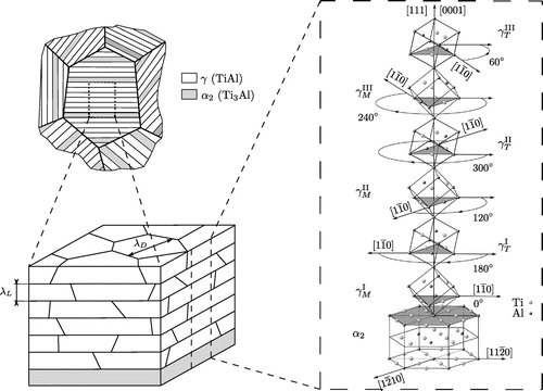
Figure 3. Experimentally determined yield stresses of polysynthetically twinned crystals under uniaxial compression for different loading angles with respect to the lamellar plane [Citation9–Citation11].
![Figure 3. Experimentally determined yield stresses of polysynthetically twinned crystals under uniaxial compression for different loading angles with respect to the lamellar plane [Citation9–Citation11].](/cms/asset/76580b38-9b0e-4b71-9d6f-f91bb37e123d/tphm_a_1070968_f0003_oc.gif)
Table 1. Slip systems in and
phase.
Every lamella is subdivided into so-called domains which all exhibit either one of the three matrix or one of the three twin orientations [Citation2,Citation30] and is called matrix or twin lamella, respectively. Different orientations within a single
lamella are separated by grain boundary-like interfaces, referred to as domain boundaries. The orientation relations are visualized in Figure .
2.2. Plastic anisotropy
The deformation of the phase is determined by crystallographic slip and twinning, while in the
phase only slip is active. Due to the atomic structure of the
lattice, the slip systems in the
phase are subdivided into so-called ordinary and super slip systems. It has been shown in
and
single-crystal experiments that their different slip and twinning mechanisms exhibit different critical resolved shear stresses [Citation31,Citation32]. However, the lamellar microstructure with the high aspect ratio of the lamellae imposes strong restrictions on activation barriers of different slip systems, so that single-crystal results are only of limited validity in the lamellar compound. The influence of different phase boundaries (i.e. interfaces between lamellae and domain boundaries within the
lamellae) is best described via the Hall–Petch relation (see e.g. [Citation34–Citation37])
(1)
Here, is the critical resolved shear stress,
represents the lattice resistance to slip,
is the Hall–Petch coefficient and
corresponds to the length a single dislocation can move before it encounters a phase boundary. Hence, slip and twinning systems parallel to the lamellar boundaries (free path length
in the
lamellae) will encounter a lower slip resistance than those whose shear deformation has to cross the lamellar boundaries (free path length
). This is the cause for the highly anisotropic behaviour in the plastic regime depicted in Figure .
To capture the plastic anisotropy of polysynthetically twinned crystals, Lebensohn et al. [Citation33] introduced a morphological classification of different slip and twinning systems into longitudinal, transversal and mixed systems. In longitudinal systems, both the slip/twinning direction as well as the slip/twinning plane are parallel to the lamellar interface. In transversal systems, neither slip/twinning direction nor slip/twinning plane are parallel to the interface. Mixed systems have their slip direction parallel to the interface, but their slip plane crosses the interface. The slip and twinning systems of both phases with the respective morphological classification are gathered in Table .
Lebensohn et al. [Citation33] further showed that one critical resolved shear stress per morphological class is sufficient to capture plastic anisotropy of polysynthetically twinned crystals in numerical simulations. So, only the three critical resolved shear stresses ,
and
have to be determined instead of one distinct critical resolved shear stress for every underlying slip/twinning system.
2.3. Yield stress anomaly
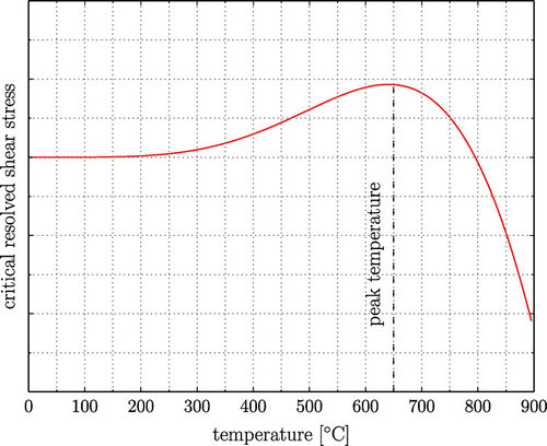
Other than in conventional structural materials, in TiAl alloys, the critical resolved shear stresses increase with temperature up to a certain peak. After this maximum, the strength decreases rapidly. This behaviour, schematically depicted in Figure , is observed in and
single crystals as well as in polysynthetically twinned crystals [Citation12,Citation31,Citation32] and is here approximated by a continuous function of temperature
, following a sinusoidal powerlaw
(2)
Figure 4. (colour online) Temperature anomaly of critical resolved shear stress in intermetallic compounds (schematic).
Herein ,
and
are constants.
3. Thermomechanical modelling
3.1. Crystal plasticity
The kinematics of crystal plasticity are based on the multiplicative decomposition of the deformation gradient into an elastic part
and a plastic part
(3)
The plastic part represents shearing of the crystal lattice due to inelastic slip along crystal planes, whereas the elastic part accounts for elastic distortion and rotation of the lattice. The split of the deformation gradient introduces an intermediate configuration. It is assumed that the normal vector of slip system
and the corresponding slip direction
remain unchanged between the reference configuration and the intermediate configuration, i.e. plastic slip does not change the appearance of the lattice.
As a deformation measure, the right Cauchy–Green tensor is introduced
(4)
In the intermediate configuration, the second Piola–Kirchhoff stress and the elastic right Cauchy–Green tensor
read
(5)
Here, denotes the Cauchy stress. The Jacobian
is given by
. With this, the Mandel stress
is introduced
(6)
Inelastic slip and twinning are assumed to obey Schmid’s law and it is assumed that slip only occurs along crystal planes. Defining the resolved shear stress in terms of the Mandel stress leads to
(7)
Mechanical twinning in the -phase is modelled as an additional slip plane which allows slip to act in twinning direction only. Furthermore, it is assumed that no slip occurs in twinned regions. These assumptions lead to the following definition of the plastic velocity gradient
(based on [Citation38,Citation39])
(8)
The slip rate on slip system and the twinning rate on twinning system
are given by
and
. The shear rate on twinning system
is defined as
multiplied by the twin shear
which is the shear deformation the lattice is undergoing if it is completely twinned [Citation40]. The volume fraction of twin
is given by
and the corresponding total twinned volume fraction is
.
The slip rate is driven by the resolved shear stress
. This is modelled using the viscoplastic power-law
(9)
Here, and
are the strain rate sensitivity exponent and the reference slip rate.
is the current slip system hardness, evolving as follows
(10)
The hardening moduli are defined as
(11)
Here, is a constant hardening factor. The constant coefficients
describe the hardening of slip system
due to slip on slip system
. With Equation (Equation11
(11) ), the hardening of the slip systems reads
(12)
The initial slip system hardness is given by
. To ensure that twinning is unidirectional, the threshold
(13)
is defined. is the constant twinning resistance and
denotes the reference twinning rate.
3.2. Thermodynamics of thermomechanical coupling
The thermomechanical coupling closely follows the concepts shown in [Citation41,Citation42]. The coupling is based on the balance of internal energy and the balance of entropy
(14)
(15)
wherein denotes the heat flux vector and
the density in the reference configuration,
is an external heat supply and
is the internal entropy production. With the second law of thermodynamics, i.e.
, Equation (Equation15
(15) ) is rewritten as
(16)
Following the hyperelastic framework, the Helmholtz free energy density is introduced. The Helmholtz free energy density is inserted into Equation (Equation16
(16) ) via its well-known form
. Inserting the energy balance into the resultant equation yields
(17)
Here denotes the temperature gradient in the reference configuration. From the split of the deformation gradient, it follows that
[Citation43]. Using standard thermodynamic arguments of Coleman–Noll [Citation44],
is a potential for the second Piola–Kirchhoff stress and the entropy
(18)
(19)
Moreover, the dissipation reads
(20)
The temperature evolution equation is derived by inserting the definition of the Helmholtz free energy density together with Equations (Equation18(18) ) and (Equation19
(19) ) into the energy balance Equation (Equation14
(14) ). With the specific heat capacity
, this yields
(21)
The last two terms on the right-hand side of Equation (Equation21(21) ) represent structural heating due to plastic and elastic deformation. Heat conduction is described by Fourier’s law, so the heat flux is given by
, with
being the heat conductivity.
The thermoelastic behaviour is modelled using a Neo–Hookean type Helmholtz free energy(22)
Here, and
are the Lamé constants,
is the thermal expansion coefficient,
is the bulk modulus and
is the absolute entropy density. The temperature
denotes the reference temperature. This leads to the following representation of the second Piola–Kirchhoff stress
(23)
3.3. Temperature-dependent material parameters of TiAl
If dealing with large temperature ranges, the temperature dependence of material parameters has to be considered. Some temperature-dependent material parameters like, e.g. Young’s modulus are easily identified from literature, see Table .
Table 2. Material parameters for simulations. The experiments were carried out in the indicated temperature range. If no parameters for the single phases are available, the parameters of the compound are used instead.
In addition, parameters for the crystal plasticity are needed. These micromechanical quantities are difficult to obtain directly from experiments – especially for high temperatures and complicated microstructures – and their temperature dependences can often not be examined independently. Therefore, temperature dependence of a few parameters is omitted here and constant room temperature values are used instead, see Table .
Table 3. ,
phase: temperature-independent micromechanical parameters.
Further, the critical resolved shear stresses ,
and
for the three morphological classes have to be determined. The critical resolved shear stresses of the
phase – as the minority phase – are modelled here according to the findings from single-crystal experiments [Citation32]. The critical resolved shear stresses of the dominant
phase are extracted from experiments with polysynthetically twinned crystals [Citation12,Citation49] to incorporate Hall–Petch strenghtening.
3.3.1. Critical resolved shear stresses for  phase
phase
From high-temperature single-crystal experiments [Citation32], it is known that the critical resolved shear stresses of the pyramidal (transverse) slip systems show the typical temperature anomaly (see Figure ), while in the prismatic (mixed) slip systems a monotonic decrease in the critical resolved shear stress is observed. Basal (longitudinal) slip has not been observed in experiments with polysynthetically twinned crystals and is therefore not modelled here.
We approximate the critical resolved shear stress of the pyramidal slip systems by the sinusoidal powerlaw (cf. Equation (Equation2(2) ))
(24)
and the one of the prismatic slip systems by the third-order polynomial(25)
In Figure , it is shown that these approximations are in good agreement with the experimental data in [Citation32].
Figure 5. (colour online) phase: experimental results [Citation32] and approximation for critical resolved shear stresses.
![Figure 5. (colour online) phase: experimental results [Citation32] and approximation for critical resolved shear stresses.](/cms/asset/4eaba981-9d7e-460f-b673-3385cfa30eb4/tphm_a_1070968_f0005_oc.gif)
3.3.2. Critical resolved shear stresses for  phase
phase
In room and high-temperature experiments [Citation12,Citation49], plastic anisotropy of polysynthetically twinned crystals was systematically analysed as a function of temperature, domain size, lamellar thickness and content. From these experiments, we extract the critical resolved shear stresses of the
phase as a function of temperature and microstructural parameters.
Since Hall–Petch related strengthening is not intrinsically considered in crystal plasticity, it is incorporated into the model of the phase via the critical resolved shear stresses. With this, the critical resolved shear stresses
,
and
are all of the general form
(26)
The results of Umakoshi [Citation12] show that the yield stresses, and therefore the critical resolved shear stresses, in polysynthetically twinned crystals under load angles of ,
and
qualitatively exhibit the temperature anomaly shown in Figure . From this, it is not possible to derive the temperature-dependent slip resistance of the lattice
and the temperature-dependent Hall–Petch coefficients independently. Hence, we assume that temperature dependence of the critical resolved shear stresses is concentrated in the Hall–Petch coefficients, that is
. We introduce two Hall–Petch coefficients
and
, denoting the strengthening by lamellar and domain boundaries, respectively. The relevant free path lengths for the longitudinal and transversal slip systems are easily identified as the domain size
and the lamellar thickness
. For mixed slip systems, we assume the free path length to be the lamellar thickness
. Together, these assumptions yield the following relations for the three critical resolved shear stresses
(27)
(28)
(29)
The temperature anomaly of the Hall–Petch coefficients is modelled once more by the sinusoidal powerlaw Equation (Equation2(2) )
(30)
(31)
The analysis of active deformation mechanisms in experiments with polysynthetically twinned crystals showed that under a load angle of , only mixed slip is active, while under
only longitudinal slip/twinning is observed [Citation10,Citation11]. Under load angles near
, only transversal slip/twinning systems are active. Thus, the three critical resolved shear stresses in Equations (Equation27
(27) )–(Equation29
(29) ) are determined from experiments at load angles of
,
and
.
In experiments under a load angle of [Citation49], critical resolved shear stresses of longitudinal slip systems in the
phase are observable as a function of the domain size
only. Extrapolating respective room temperature results [Citation49] to
, yields
30 MPa.
Assuming MPa
, the six remaining model parameters
,
and
are found by fitting Equations (Equation28
(28) ) and (Equation29
(29) ) to the temperature-dependent results for
and
from [Citation12], see Table .
Table 4. phase: approximation of temperature-dependent Hall–Petch coefficients.
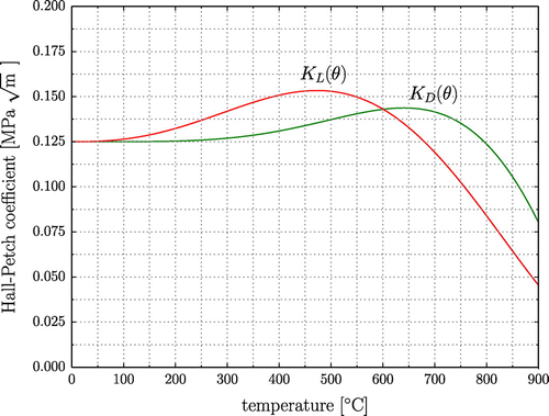
Figure depicts and
over temperature. The curves exhibit peaks near 700
C respective
C. Therefore, the critical resolved shear stresses
and
are maximal near
C and
exhibits a peak near
C as observed in the respective yield stresses in [Citation12].
4. Numerical results
4.1. Finite element model
The described material model is implemented into the finite element software Abaqus via a user material subroutine. The highly non-linear and coupled system of equations is solved in each time step with an elastic predictor – plastic corrector scheme using a Newton–Raphson algorithm. The computational experiments are set up as a fully coupled thermal stress analysis with a monolithic solution scheme. Herein, the structural heating terms from Equation (Equation21(21) ) are taken into account.
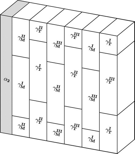
For modelling the fully lamellar microstructure of a polysynthetically twinned crystal, a RVE is set up, see Figure . The volumetric contents of the and
phases are captured by changing the width of the
lamella while keeping the width of the RVE constant. The six different
phases are assumed to occur with equal volume fractions. The geometry shown in Figure is discretized using linear hexaeder elements with temperature degrees of freedom (C3D8T). Periodic boundary conditions are applied to displacements as well as temperature. To change the load angle, the RVE is rotated within a dummy element as explained in [Citation24].
4.2. Simulation
The numerical results presented here are all determined for uniaxial compression with a strain rate of . A homogeneous temperature distribution is assumed as initial condition.
4.2.1. Plastic anisotropy at room temperature
In Figure , the predicted plastic anisotropy at room temperature is compared to experimental results. Uhlenhut’s results [Citation11] exhibit a higher yield stress at the extreme load angles of and
than the results of the other referenced authors, although all shown experiments were carried out with a similar composition. This indicates that both, domain size and lamellar thickness, are smaller in Uhlenhut’s specimens. With a constant
content of 8 Vol.%, the lamellar thicknesses
m and
m and the domain sizes
m and
m are well suited to demonstrate the capability of the model to capture the plastic anisotropy.
Figure 8. (colour online) Yield stress of polysynthetically twinned crystals under uniaxial compression as a function of the angle between loading direction and lamellar plane ( Vol%;
C).
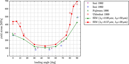
The simulated yield stresses in Figure show a very good agreement with the experimental results not only at the characteristic points, i.e. load angles ,
and
, but also at intermediate load angles.
4.2.2. Temperature dependence of yield stress
In Figure , the simulated yield stress as a function of temperature is compared to the findings of Umakoshi et al. [Citation12] and Inui et al. [Citation50]. Comparison to Umakoshi’s findings (Figure (a)) shows that the model captures the characteristics of the experimental curves very well. The peaks in the and
curves and the rise of the yield stress from room temperature to peak temperature correspond to the ones observed in experiments. As in the experiments, no distinct peak is observable in the yield stress under a
load angle. However, the yield stress is underestimated in all three orientations. Since the present approximation of the temperature-dependent Hall–Petch relation incorporates interrelations of several microstructural parameters – determined from an inherent experimental scattering –, a certain quantitative deviation in the yield stress is inevitable.
Figure 9. (colour online) Yield stress of polysynthetically twinned crystals under uniaxial loading as a function of temperature.
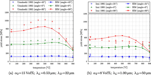
Comparison to Inui’s findings (Figure (b)) shows a good quantitative and qualitative agreement for and
load angles. For the latter, however, the peak in the experimental results occurs at a slightly higher temperature than in simulations. In the
experiments, Inui et al. [Citation50], in contrast to Umakoshi et al. [Citation12], did not observe a peak in yield stress.
4.2.3. Influence of lamellar thickness and domain size
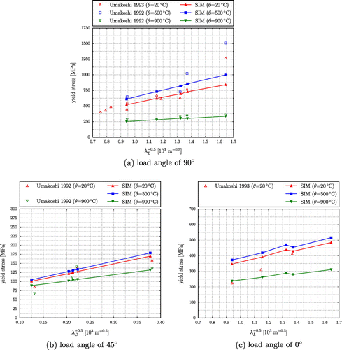
To evaluate the influence of lamellar thickness and domain size on yield stress, micromechanical lengths are systematically altered. Since it is not possible to alter content, lamellar thickness and domain size independently during the alloying process, the analysis is carried out for the parameter combinations of the sample materials in Table corresponding to the material compositions analysed by Umakoshi et al. [Citation12,Citation49].
Table 5. Microstructural parameters from [Citation12,Citation49].
Figure shows the respective simulation results together with experimental data. Comparison of the results yields a good agreement for load angles of and
. The simulated Hall–Petch slopes are near the experimental ones and change properly with temperature. The deviations between the simulated and the experimental yield stresses are mostly in the range of the experimental scattering. For
C, the yield stress under a load angle of
is underestimated by the model. However, for this orientation and temperature, the scattering in the experimental results is striking so that it is hard to enhance the model without further information.
Under a load angle of , only room temperature experiments are available [Citation49]. The simulation results for
C and
C are shown for the sake of completeness. At room temperature, the Hall–Petch slope of simulations is slightly lower than in experiments. However, if extrapolated to
, the Hall–Petch slope of the respective experiments yields negative values for
. This contradicts the basic idea of the Hall–Petch relation and indicates that the three available experimental data points might not be enough. For all values of
, the yield stress in this orientation is overestimated by the model. This indicates that the free path length for the mixed slip systems is somewhat bigger than assumed, but still in the vicinity of the lamellar thickness
.
5. Conclusion
The main objective of the present model is to provide a reliable prediction of the yield stress of polysynthetically twinned crystals as a function of
load angle,
lamellar thickness
and domain size
,
temperature (including the temperature anomaly),
and
-content.
In some previously reported models, the Hall–Petch relation Equation (Equation1(1) ) is considered by precalculating the critical resolved shear stresses
as a temperature-independent input for the simulations [Citation26,Citation28,Citation29]. This approach is suitable for a homogeneous temperature field, but not sufficient in a fully coupled thermomechanical analysis. In a fully coupled analysis, the temperature field may vary locally due to structural heating or thermal loading. Hence, the present model includes the derived temperature-dependent Hall–Petch relation as a constitutive equation which is evaluated locally during simulations. This enables the model to predict the yield stress for, e.g. inhomogeneous temperature fields or thermal cycling. This feature especially becomes relevant in simulations of bigger microstructures including, e.g. several colonies.
In construction design with TiAl, the weakest colonies, i.e. colonies near an angle of between lamellar plane and principle stresses, determine the overall strength of the alloy. In these intermediate orientations, the present model predicts the temperature-dependent yield stresses very well for all investigated combinations of
and
. In terms of micromechanics, a polysynthetically twinned crystal is basically the same as a single colony. A proper discretization presupposed, it can therefore be assumed that the model is also able to correctly predict the yield stress of a fully lamellar microstructure with several colonies as a function of the above-listed parameters. The present model is therefore a good basis for further investigations of the thermomechanical behaviour of TiAl alloys on the meso scale.
Acknowledgements
We gratefully acknowledge personal conversations with Florian Pyczak and Marcus Rackel (both Helmholtz-Zentrum Geesthacht, Germany) and thank for the provided graphical material.
Notes
No potential conflict of interest was reported by the authors.
References
- H. Clemens and S. Mayer, Mater. Sci. Forum 783–786 (2014) p.15.
- M. Yamaguchi, H. Inui and K. Ito, Acta Mater. 48 (2000) p.307.
- A. Lasalmonie, Intermetallics 14 (2006) p.1123.
- D.M. Dimiduk, Mater. Sci. Eng. A 263 (1999) p.281.
- T. Tesui, Mater. Sci. Eng. A329–331 (2002) p.582.
- Y.W. Kim, Acta Metall. Mater. 40 (1992) p.1121.
- F. Appel and R. Wagner, Mater. Sci. Eng. R22 (1998) p.187.
- S. Gebhard, F. Pyczak and M. Göken, Mater. Sci. Eng. A 523 (2009) p.235.
- H. Inui, M.H. Oh, A. Nakamura and M. Yamaguchi, Acta Metall. Mater. 40 (1992) p.3095.
- T. Fujiwara, A. Nakamura, M. Hosomi, S.R. Nishitani, Y. Shirai and M. Yamaguchi, Philos. Mag. A 61 (1990) p.591.
- H. Uhlenhut, Ursachen plastischer Anisotropie von у-TiAl-Basislegierungen [Causes of plastic anisotropy of у-TiAl based alloys] Ph.D. thesis, Technischen Universität Hamburg-Harburg, 1999.
- Y. Umakloshi and T. Nakano, ISIJ Int. 32 (1992) p.1339.
- G. Wegmann, T. Suda and K. Maruyama, Intermetallics 8 (2000) p.165.
- H.Y. Kim, G. Wegmann and K. Maruyama, Mater. Sci. Eng. A 329--331 (2002) p.795.
- T. Asai, S. Hirata, M. Takeyama and T. Matsuo, Mater. Sci. Eng. A 329–-331 (2002) p.828.
- D.Y. Seo, C.H. Wu and T.R. Bieler, Mater. Sci. Eng. A 239--240 (1997) p.450.
- C. Zambaldi, F. Roters and D. Raabe, Intermetallics 19 (2011) p.820.
- B.K. Kad, M. Dao and R.J. Asaro, Philos. Mag. A 71 (1995) p.567.
- R. Lebensohn, Model. Simul. Mater. Sci. Eng. 7 (1999) p.739.
- R.A. Brockmann, Int. J. Plast. 19 (2003) p.1749.
- M. Grujicic and S. Batchu, J. Mater. Sci. 36 (2001) p.2851.
- M. Grujicic, G. Cao and S. Batchu, J. Mater. Sci. 38 (2003) p.307.
- M. Werwer and A. Cornec, Int. J. Plast. 22 (2006) p.1683.
- M. Werwer and A. Cornec, Comput. Mater. Sci. 19 (2000) p.97.
- S.M. Schlögl and F.D. Fischer, Comput. Mater. Sci. 7 (1996) p.34.
- S.M. Schlögl and F.D. Fischer, Philos. Mag. A 75 (1997) p.621.
- S.M. Schlögl and F.D. Fischer, Mater. Sci. Eng. A 239--240 (1997) p.790.
- E. Parteder, T. Siegmund, F.D. Fischer and S. Schlögl, Mater. Sci. Eng. A 192 (1995) p.149.
- M. Kabir, L. Chernova and M. Bartsch, Acta Mater. 58 (2010) p.5834.
- H. Inui, M.H. Oh, A. Nakamura and M. Yamaguchi, Philos. Mag. A 66 (1992) p.539.
- H. Inui, M. Matsumuro, D.H. Wu and M. Yamaguchi, Philos. Mag. A 75(2) (1997) p.395.
- Y. Umakoshi, T. Nakano, T. Takenaka, K. Sumimoto and T. Yamane, Acta Metall. Mater. 41 (1993) p.1149.
- R. Lebensohn, H. Uhlenhut, C. Hartig and H. Mecking, Acta Mater. 46 (1998) p.4701.
- B.K. Kad and R.J. Asaro, Philos. Mag. A 75 (1997) p.87.
- D.M. Dimiduk, P.M. Hazzledine, T.A. Parthasarathy, S. Seshagiri and M.G. Mendiratta, Metall. Mater. Trans. A 29A (1998) p.37.
- Y.-W. Kim, Intermetallics 6 (1998) p.623.
- K. Kishida, D.R. Johnson, Y. Masuda, H. Umeda, H. Inui and M. Yamaguchi, Intermetallics 6 (1998) p.679.
- J. Rice, J. Mech. Phys. Solids 19 (1971) p.433.
- F. Roters, P. Eisenlohr, L. Hantcherli, D. Tjahjanto, T. Bieler and D. Raabe, Acta Mater. 58 (2010) p.1152.
- F. Appel, J.D.H. Paul and M. Oehring, Gamma Titanium Aluminide Alloys, Wiley-VCH Verlag GmbH & Co, KGaA, Weinheim, 2011.
- S. Bargmann and M. Ekh, Int. J. Solids Struct. 50 (2013) p.899.
- A. McBride, S. Bargmann and D. Reddy, Comput. Mech. 55 (2015) p.755.
- M. Scheidler and T.W. Wright, Int. J. Plast. 17 (2001) p.1033.
- B.D. Coleman and W. Noll, Arch. Ration. Mech. Anal. 13 (1963) p.167.
- R.E. Schafrik, Metall. Mater. Trans. A 8A (1977) p.1003.
- T. Novoselova, S. Malinov, W. Sha and A. Zchecheva, Mater. Sci. Eng. A 371 (2004) p.103.
- I. Egry, R. Brooks, D. Holland-Moritz, R. Novakovic, T. Matsushita, E. Ricci, S. Seetharaman, R. Wunderlich and D. Jarvis, Int. J. Thermophys. 28 (2007) p.1026.
- W. Zhang, B. Reddy and S. Deevi, Scr. Mater. 45 (2001) p.645.
- Y. Umakoshi and T. Nakano, Acta Mater: Metall. 41 (1993) p.1155.
- H. Inui, K. Kishida, M. Misaki, M. Kobayashi, Y. Shirai and M. Yamaguchi, Philos. Mag. A 72 (1995) p.1609.

