Abstract
It is customary to simplify the analysis of contact between two elastically deformable bodies by treating an equivalent problem where only one body is deformable and the other is rigid. This is possible provided that the gap geometry and the effective elastic modulus of the bodies in the simplified problem are the same as in the original problem. However, the question arises on whether – and to which extent – the simplification is still valid even when (size-dependent) plasticity occurs. Studies using discrete dislocation plasticity have also, so far, addressed simple contact problems where only one body can deform plastically. Here, we extend the analysis to two bodies in contact that can both deform by dislocation plasticity and investigate under which conditions the response agrees with that of an equivalent simplified problem. The bodies in contact are metal single crystals with sinusoidal and flat surface. It is found that the response of two plastically deformable bodies in contact can be simplified to an equivalent problem where one body is rigid and the other can deform plastically. Also, a plasticity size effect is observed, but the effect fades when the platen becomes more plastically deformable.
1. Introduction
Friction and wear of surfaces play a paramount role in the performance of many engineering machines, especially of micron and smaller sized devices in which surface effects become dominant [Citation1–Citation4]. These dissipative phenomena generally reduce the reliability and robustness of micron-sized devices such as actuators or motors as they result in wear of contact junctions [Citation5,Citation6]. Most importantly, friction can compromise functioning of micron-sized machines by preventing relative motion of parts, a phenomenon commonly referred to as stiction. Clearly, to control and enhance the reliability and performance of these miniaturised devices, the behaviour of the deforming bodies in contact must be understood.
Recently, discrete dislocation plasticity simulations have been carried out to analyse the contact behaviour of micrometre-sized metal crystals [Citation7–Citation10]. The choice of this method is linked to the scale considered, which is too computationally expensive to be studied using molecular dynamics [Citation11,Citation12]. Local and non-local continuum plasticity models [Citation13–Citation15] are also not suitable as they do not capture the effects caused by the discreteness of plastic carriers [Citation16], e.g. source limitation effects [Citation17–Citation19], patchy contact areas and highly localised contact pressure peaks [Citation20]. Discrete dislocation plasticity accounts for these effects as it considers the nucleation and glide of individual dislocations [Citation8,Citation10].
So far the mechanical behaviour of contact between micrometre-sized sinusoidal asperities, or protrusions of a surface, and a rigid [Citation8] or an elastic platen [Citation10] has been investigated using discrete dislocation plasticity. A plasticity size effect is observed, for which smaller asperities are harder to deform. The size effect decreases with increasing compliance of the platen [Citation10]. Here, we extend the analysis to two bodies that can deform by dislocation plasticity. Simulations of contact between a body with micron-sized sinusoidal asperities and a platen are performed. A plasticity size dependence is also present, but it fades when the platen is more plastically deformable, similar to what is observed when the platen compliance is increased.
To model the contact behaviour of two deformable bodies, several local continuum contact studies simplify the problem to treat either a body having asperities in contact with a rigid flat body [Citation21–Citation26], or a rigid rough body in contact with a flat body [Citation27–Citation29]. This is because the elastic mechanical response of the two systems is the same, provided that the gap geometry and the effective elastic modulus of the bodies are the same (see, e.g. [Citation27]). The stresses in the region directly above and below the contact are also approximately the same, and they are a function of the effective elastic modulus, and not the elastic properties of each body. Thanks to this equivalence, only the deformation of one body has to be considered since contact with the rigid body can be mimicked through boundary conditions. However in these studies, the deformable body also undergoes plastic deformation, and the validity of this simplification has been questioned [Citation24,Citation26,Citation30,Citation31]. Can we use the simplified problem to predict the behaviour of contact between two micrometre-sized crystals?
To answer this question, we need to find out if the plastic properties of two crystals can be mapped to the plastic properties of one body in contact with a rigid body. We begin first by understanding the effect of surface geometry on the plastic response. To this end, we investigate whether flattening of a sinusoidal body by a rigid platen is equivalent to the indentation of a platen by a rigid sinusoidal body, even when plasticity occurs. Next, we study how the contact response is affected when changing plastic properties of the bodies, i.e. dislocation source density and their critical strength as well as obstacle density and strength. Finally, we determine which criteria should be met by an equivalent simplified system, in order to represent contact deformation between two plastically deforming metal crystals.
2. Discrete dislocation plasticity for two bodies in contact
Here, we will briefly describe the formulation of contact between two frictionless bodies that can deform by dislocation plasticity; details can be found in [Citation10]. Contact between the bodies is dealt with a constrained minimisation problem. Consider first two linear elastic bodies in contact. Each body i has domain bounded by a boundary
where
and
is the contact surface. Superscripts enclosed in brackets refer to the body in consideration. The total potential energy functional
, neglecting body forces, is given as
(1)
where and
are the strain and stress tensors,
are the displacement vector fields, and
are the tractions acting on the boundary
. For the two-dimensional contact problem considered here, the constraint energy term
for frictionless contact is expressed, following the penalty method, as
(2)
The gap function in Equation (Equation2
(2) ) describes the normal distance between two points on opposite surfaces, and
is the penalty parameter, which has the goal to minimise surface penetration. When
surfaces are in contact, otherwise, the surfaces are contact-free [Citation10]. Note that the relative displacement of the contact is not constrained in tangential direction, to satisfy the frictionless contact condition. The potential energy functional minimum is obtained by equating the first variation of
to zero [Citation32,Citation33],
(3)
The displacement fields in each body i are decomposed into two additive linear elastic fields:
and
. The dislocation displacement fields
are the analytical fields of the edge dislocations contained in body i as if the fields were unbounded. When calculating displacement fields in body i, dislocations in body j are ignored. The image fields
become the new unknown in Equation (Equation3
(3) ). Since the
fields are smooth, it is possible to use the finite element method and follow standard procedures to express Equation (Equation3
(3) ), together with
, in discrete form as,
(4)
where the nodal quantities are indicated by an asterisk, and is the external load vector.
and
are the body stiffness and penalty contact stiffness matrix, respectively. The contact stiffness matrix
is non-zero only at
. Equation (Equation4
(4) ) is solved iteratively to obtain
, while satisfying the contact constraints, and the boundary conditions:
(5)
The external displacements are applied on the boundary . At each time increment,
,
and
in the bodies are given as the sum of the dislocations fields
and the image fields
,
(6)
Figure 1. (colour online) Decomposition of the incremental solution of a contact problem solved by discrete dislocation plasticity. For simplicity of representation, only the decomposition of the fields in body 1 is shown: the decomposition of the fields is analogous for body 2. Contact is frictionless.
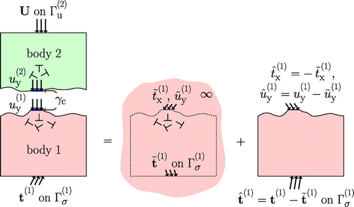
A schematic representation of the decomposition of the fields in body 1 for a frictionless contact problem is given in Figure . The same decomposition is used for the fields inbody 2.
2.1. Dislocation dynamics
Dislocation dynamics are modelled by constitutive rules that govern dislocation nucleation, pinning at/depinning from obstacles, annihilation and glide along slip planes. These rules are briefly described here. The reader is referred to [Citation34,Citation35] for more details.
Three potentially active sets of slip planes are considered based on the two-dimensional representation of the FCC crystal structure [Citation36]. Here, each set k of parallel slip planes are oriented at , and
, unless otherwise stated. Heterogeneous dislocation sources of Frank–Read character and obstacles are randomly distributed along the slip planes throughout the initially dislocation and stress-free bodies. A dislocation dipole nucleates when the resolved shear stress
exerted on a dislocation source exceeds its critical strength
over a certain time interval
. The nucleation length
for each dipole is
(7)
where and
are the shear modulus and Poisson’s ratio of the material, respectively. Glide of the dislocations along the slip planes in the crystal is governed by a simple constitutive equation which relates the velocity
of dislocation i to the resolved Peach–Koehler force
through the drag coefficient D:
(8)
An obstacle present in the material pins approaching dislocations at its location. However, if the shear stress exerted by the dislocation on that obstacle exceeds the obstacle strength , or if the dislocation moves in the opposite direction, the dislocation breaks free and regains its mobility. Obstacles are placed on slip planes that contain at least one dislocation source. If dislocations of opposite signs (dipole) approach each other too closely on the same slip plane, they will annihilate. If the path of a dislocation crosses the surface of the crystal at the contact or elsewhere, the dislocation escapes, leaving a crystallographic step of magnitude b at the surface. Given that the surface profile is modified by the step, the step is added to the surface displacement term
in the normal gap function (Equation (Equation2
(2) )) [Citation10]. The process of finding the contact solution remains unchanged.
Dislocation plasticity is inherently stochastic due to the statistical nature of the source and obstacle positions and the source strengths [Citation10,Citation37,Citation38]. Here, we perform eight realisations for each case to obtain the average response. Each realisation differ in the location of the sources and obstacles in the body, and the source strengths, which are normally distributed.
3. Contact between a platen and a body with a sinusoidal surface
Figure illustrates the problem of contact between two metal crystals under plane strain conditions. Both crystals deform plastically by edge dislocations gliding along three sets of slip planes oriented at an angle with the x direction. The surface profile of body 1, the bottom crystal, is described by a sinusoid with wavelength
and amplitude
. Each wave of the sinusoid represents an asperity. Body 2, the top crystal, has a flat surface profile. The heights of body 1 and body 2 are
and
, respectively, where
. Heights
and
are both
, sufficiently large that dislocation activity in the crystal is confined to the region directly beneath the contact. This is to avoid that dislocations interact with the bottom of the crystal. The analysis is performed on a unit cell with a periodicity
, where periodic boundary conditions are imposed,
.
Figure 2. Two-dimensional model of a single crystal with sinusoidal surface in contact with a flat single crystal. Sources () and obstacles (
) are homogeneously distributed in the bodies.
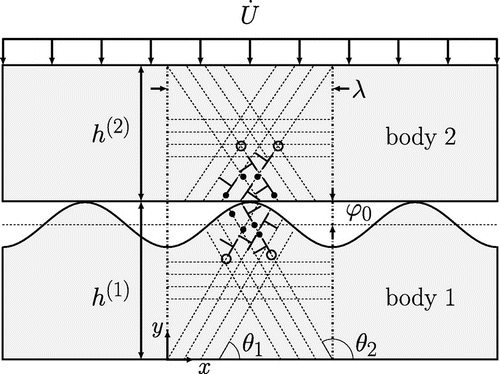
Table 1. List of material properties used in the simulations to characterise the single crystal.
To establish contact, a uniform displacement is applied on the top surface of body 2,(9)
where is the displacement loading rate. The base of body 1 is fixed in the y direction
, and to prevent rigid body translation,
.
4. Results
4.1. Size-dependent response of two plastically deforming bodies
Discrete dislocation plasticity simulations demonstrate that the plastic behaviour of micron-sized scaled asperities flattened by a rigid [Citation8] or an elastic platen [Citation10] is size- dependent. Here, we investigate if the size-dependent plastic response is significant when both the asperity and platen can deform plastically. We simulate contact between crystals that have both the properties as given in Table , unless otherwise stated.
The effective elastic modulus for the two crystals in contact is
GPa.
The asperities have constant aspect ratio, , and
and
. The mean apparent pressure
is considered, where
is the apparent area calculated as the distance between the outermost contact edges, and
is the unit y vector. The normalised pressure
is presented in Figure (a) as a function of strain
, defined as
. Here
and
are the current and initial average gap (Figure (b)). Elastically,
for both cases overlap [Citation10].
For both crystals in contact, the normalised apparent pressure at the onset of plasticity is larger for the smaller asperity, indicating a size effect. At larger strains, the hardening rates are not size-dependent. This is because plasticity is source limited only for very small contact sizes, when the critical stress region (where ) is small and therefore deprived of dislocation sources. A similar size dependence is found when flattening scaled micron-sized asperities using an elastic platen [Citation10].
The plasticity size dependence is less pronounced when the stiffness of the platen decreases [Citation10]. The size effect is expected to also diminish when the platen can deform more plastically, which is similar to decreasing the stiffness of the platen. Here, we consider a platen with three different source densities, i.e. = 30, 120 and
, in contact with the asperities. The other material properties of the platen remain unchanged. As expected, when the source density of the platen is increased, for instance from
(Figure (a)) to
(Figure (b)), almost all plasticity occurs in the platen.
Figure 3. (colour online) (a) The normalised apparent pressure, , for scaled asperities in contact with a platen, both bodies having the same properties. (b) Schematics to illustrate the definition of strain,
.
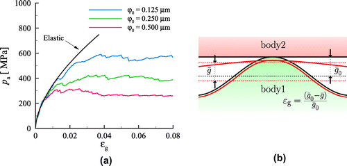
Figure 4. (colour online) Stress and dislocation distributions for contact between bodies with (a)
and (b)
at strain offset of 2 % for
. (c) Apparent pressure
at
offset strain as function of asperity volume
for three different platen source densities
. Each vertical bar is the standard deviation obtained from eight simulations.
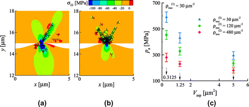
Figure (c) shows the apparent pressure taken at strain offset with respect to the asperity volume
for a platen having different source densities
. Indeed when the source density
is increased, not only
is decreased, the size effect also fades. Obviously, in the continuum limit, no size effect will be observed.
4.2. Effect of surface geometry
Here, we investigate how the plastic behaviour of the bodies in contact depends on surface geometry. To this end, we consider two limit cases: flattening, where plasticity occurs only in the body with a sinusoidal surface, and indentation, where plasticity occurs only in the platen. The other body in contact is rigid, and has a Young’s modulus ;
is sufficiently small to prevent ill-conditioning of the finite element stiffness matrix. The plastically deformable body in each case has the material properties listed in Table . The asperity has
and
.
Figure 5. (colour online) (a) The apparent pressure for both flattening and indentation, when the sinusoidal asperity has . Each vertical bar is the standard deviation obtained from eight simulations. (b) The corresponding apparent area for both cases. (c) Pressure difference for the two cases taken at
for various gap geometries.
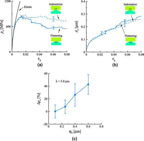
Figure (a) shows that the mean apparent pressure is larger during indentation. The apparent area is the same for both flattening and indentation (Figure (b)). This shows that the plastic contact response does not only depend on the gap geometry and effective elastic modulus, but also on the surface geometry. As to be expected, the difference in contact pressure increases with increasing the amplitude of the sinusoid (Figure (c)), but is however, given the large scatter of the results, only appreciable for .
Figure 6. (colour online) (a) Ratio of slip: slip obtained during flattening to slip during indentation for different , and (b) ratio of number of escaped dislocations from
slip planes to the total number of dislocations for the plastically deformed asperity for
.
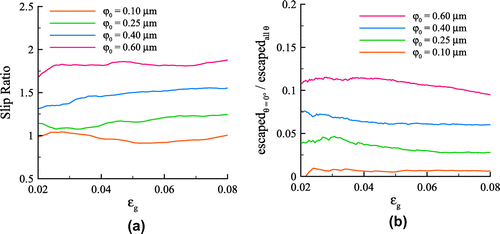
Given that the elastic stress distribution in the platen is very similar to that in the sinusoidal body for all amplitudes considered, it is far from self-evident what causes the different plastic response. The amount of slip caused by dislocations gliding in the sinusoidal body during flattening is larger than that obtained by dislocations gliding in the flat body during indentation, as testified by the slip ratio in Figure (a). The slip is obtained by integrating the total plastic shear strain of the three slip plane systems over the volume of the body. As increases from 0.1 to
, the slip increases for the flattening case. What causes this increase?
We know that dislocations nucleated on the slip planes normal to the loading direction, with , can escape the sinusoidal surface. When this happens, more nucleations and dislocation glide can occur, which results in larger slip. Increasing the amplitude of the sinusoid,
, increases the number of slip planes with
, and hence the number of escaped dislocations from these slip planes in the plastically deformable asperity (Figure (b)). This hypothesis is confirmed by performing simulations with only symmetric double slip (
and
slip planes) for
and
. Indeed as seen in Figure (a),
is statistically the same for both flattening and indentation.
Figure 7. (colour online) (a) Mean apparent pressure for and
for symmetric double slip. (b) Pressure difference (in %) between flattening and indentation at strain
when
for different
. Each vertical bar is the standard deviation obtained from eight simulations.
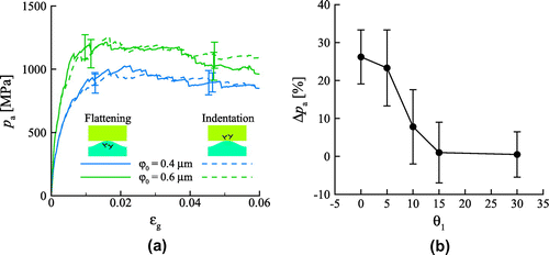
We also do not expect a difference between the flattening and indentation cases when none of the three active slip planes is oriented at . Figure (b) shows the percentage pressure difference between the cases for
and
when
at
. Indeed as
increases,
decreases until no appreciable difference is observed at
.
Since the likelihood of slip planes being oriented at angles near is small, and that asperities have
for most real surfaces [Citation39], the number of slip planes that begin and end in the asperity is small. This means that the plastic response of flattening a body with sinusoidal surface with a rigid flat body can be considered the same as indenting a flat body with a rigid body with sinusoidal surface.
4.3. Effect of source density
Here, we investigate how the response is affected by changing the dislocation source density. To this end, we take the liberty to change the source density in each body while keeping the other material properties unchanged. The total source density
, is kept constant. Three different source densities in each body are considered:
;
; and
. The asperity has
so that the asperity is not too protruding, and the first set of slip planes is oriented at
, to eliminate any difference in the plastic response resulting from the orientation of the slip planes (see Section 4.2).
Figure 8. (colour online) The mean apparent pressure for different density of sources in the bodies. The total source density is constant, .
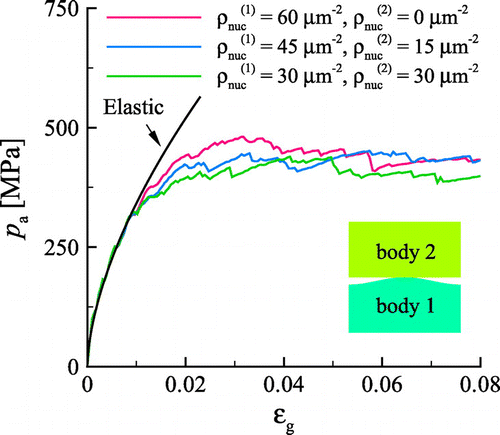
Figure 9. Schematics of sources () in the critical stress zone,
, bounded by a dashed line for (a) both bodies with
and (b) only the bottom body containing sources having a source density equal to
of the bodies depicted in (a).

Figure 11. (colour online) (a) Mean apparent pressure for bodies having different obstacle densities . Plastic shear strain and dislocation distributions for (b)
and (c)
at strain
.
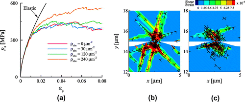
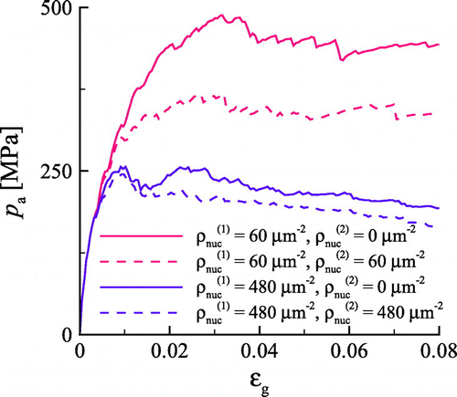
Figure shows that the mean apparent pressure is unaffected by varying the source density in the bodies with the same . The plastic response is similar because: (1) the critical elastic stress zone, where
, has approximately the same size in both bodies, and (2) the dislocation sources are homogeneously distributed in one or both crystals. It follows that the density of dislocation sources in the critical stress zone depends on
and not on the source density of each body (see Figure ). Those sources are the ones that sustain plastic deformation, and it is not relevant whether slip occurs only in one body or in both, only its total amount. Clearly, increasing the total source density,
, will decrease the mean contact pressure, as can be seen in Figure where results are presented for
= 60, 120, 480 and 960
. Notice, however, that for the larger source density
= 960
, the response is unaffected by increasing the number of sources (see the tiny difference between
and
). This is because the number of sources is so large that the continuum limit is approached. At this limit, yield occurs in the material wherever the yield strength is exceeded due to the large availability of sources. This shows that the contact response is a function of the total source density only when the plastic behaviour is source limited, but not in the continuum limit.
4.4. Effect of obstacles
The effect of changing the obstacle density on the mechanical response is next investigated. Only the obstacle density is varied, with
= 0, 30, 60, 120 and
. The obstacle strength is
. All other body properties are the same as in the previous section. Figure (a) shows that only for
, the apparent contact pressure is larger. Although increasing
decreases the average free path of dislocations (hence the slip provided by each dislocation), more dislocations are nucleated in response to the larger stresses, accounting for the required total glide. At larger obstacle densities however, the obstacle spacing d approaches the nucleation length
(
) of the dipole, greatly decreasing the distance a dislocation can glide right after it is nucleated, resulting in lesser slip and lesser stress relaxation. For instance, at
, the magnitude and extent of plastic slip are much larger when
(Figure (b)) than when
(Figure (c)), even if the dislocation density is larger when
.
Figure 12. (colour online) (a) Mean apparent pressure for two crystals with same material properties in contact and contact between a rigid body and the single body with the same and gap geometry. (b) Contact pressure distribution for a particular realisation and (c) average contact pressure distribution at
for both contact problems.
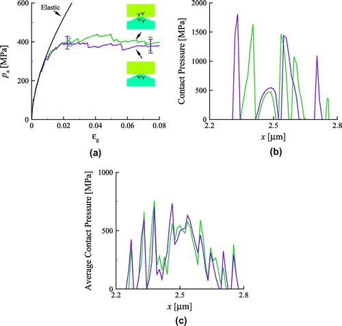
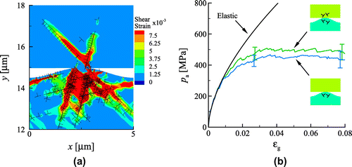
Figure 13. (colour online) (a) Plastic shear strain and dislocation distributions for contact between sinusoidal body having a source strength MPa and a platen having a source strength
MPa at
for a particular realisation. (b) The mean apparent pressure for two crystals in contact and the corresponding equivalent system.
The results are found also to apply for . A previous study of wedge indentation of a single crystal using discrete dislocation plasticity [Citation40] also shows that the contact pressure is only marginally affected by the obstacle density and strength. Therefore, the obstacle density and strength need not be considered when analysing the mechanical response of contact between bodies that can deform by dislocation plasticity, provided the average obstacle spacing d is not too small compared with
: here
.
4.5. Equivalent systems: mapping two plastic bodies in contact into a single plastic body in contact with a rigid body
4.5.1. Crystals with the same material properties
In this section, we explore the possibility of representing two plastically deformable bodies in contact by an equivalent system made of a rigid body in contact with a single plastically deformable body. The gap geometry and of the bodies in the equivalent system are the same as the two crystals in contact.
The contact pressure of two crystals with the same material properties in contact is compared with the pressure obtained from the equivalent system. The deformable body in the equivalent system has , to give
, and a source density equal to the total source density,
, of the two crystals. This is because results from previous sections showed that the sources can be apportioned among the bodies without affecting the response, provided that the asperity is not too protruding (Section 4.2), and
remains unchanged (Section 4.3). The obstacle density need not be considered (Section 4.4). All the other plastic properties are unchanged.
The mean apparent pressure in Figure (a) shows a very good agreement between the response of the two bodies in contact and the equivalent system. The agreement is, as expected, less good in terms of contact pressure profiles, shown in Figure (b). Given the discrete nature of dislocations and slip planes, the pressure peaks have a statistical character and cannot correspond one-to-one [Citation10]. However, the average contact pressure profiles for both problems converge (Figure (c)), indicating that the two bodies in contact and the equivalent system behave on average, identical.
Results show that two crystals of the same material in contact can be represented by an equivalent system of a rigid body in contact with a deformable body, provided that the gap geometry, , and the total source density remain unchanged. This result also holds true in the continuum limit: the deformable body in the equivalent system will be described by the same constitutive plastic law as any of the bodies in the original problem.
4.5.2. Crystals with different source strengths
The problem becomes more complicated when the crystals in contact have different source strengths . Here, we simulate contact between a sinusoidal body having a source strength
MPa and a platen having a source strength
MPa, while keeping other properties unchanged. As expected, plastic slip occurs mainly in the softer sinusoidal body (Figure (a)). The source strength
of the equivalent system is taken to be that of the softer material. Since the effect of increasing
has a similar effect as decreasing
, we estimate the source density
by weighing each source density by the source strength:
(10)
which gives . Note that Equation (Equation10
(10) ) holds only when the plastic behaviour is source limited, but not in the continuum limit (see Section 4.3).
The mean apparent pressure is given in Figure (b) for the original and the simplified equivalent problems. Within statistical variations, the average responses obtained are approximately the same. Since the contact response of bodies with different source strengths is dominated by plastic activity in the body with a smaller source strength, we can simplify the two body problem into an equivalent problem of contact between a deformable body and a rigid body, provided that the strength of the sources in the deformable body is that of the softer material, and the source density follows Equation (Equation10(10) ). In continuum plasticity, this means that the deformable body in the simplified equivalent system should have the constitutive plastic law describing the softer material.
5. Conclusions
Two-dimensional discrete dislocation plasticity simulations of contact are performed for bodies that can both deform plastically. Here, we focus only on contact between a body with sinusoidal profile and a platen.
A size effect involving the onset of plasticity is present. This is attributed to source limitation in both bodies at the onset of plasticity, similar to what is observed in previous discrete dislocation plasticity simulations of contact where only the sinusoidal body deforms plastically. A plasticity size dependence is observed, but the effect diminishes when the platen is more plastically deformable. In the continuum limit, no size effect will be observed.
For (sub)-micrometre-sized contacts, the contact response depends on the total sum of the source densities of both bodies, and not on how the dislocation sources are apportioned in the bodies. This holds provided that the sources are homogeneously distributed in each body, and that the asperities are not too steep.
Following the above result, and the observation that real surfaces have generally asperities that are not too protruding, we found that the problem of non-conformal contact between two metal crystals can be simplified into a problem of a single plastically deformable body in contact with a rigid body, provided that
the gap geometry and the effective elastic modulus are the same,
the source strength in the equivalent system is the source strength of the softest body in the original problem,
the source density-to-strength ratio in the equivalent system is estimated by adding the density-to-strength ratios of the two bodies in the original problem.
It is therefore possible to use an equivalent system made of a single body in contact with a rigid platen to predict the plastic contact behaviour of two metal crystals, which is advantageous since only one body is to be considered in the analysis, and the effects of the rigid body can be mimicked by a set of boundary conditions at the contact.
Additional information
Funding
Notes
No potential conflict of interest was reported by the authors.
References
- R. Maboudian, Surface processes in MEMS technology, Surf. Sci. Rep. 30 (1998), pp. 207–269.
- L. De Chiffre, H. Kunzmann, G.N. Peggs, and D.A. Lucca, Surfaces in precision engineering, microengineering and nanotechnology, CIRP Ann. Manuf. Technol. 52 (2003), pp. 561–577.
- B. Bhushan, Nanotribology and nanomechanics of MEMS/NEMS and bioMEMS/bioNEMS materials and devices, Microelectron. Eng. 84 (2007), pp. 387–412.
- A.A.G. Bruzzone, H.L. Costa, P.M. Lonardo, and D.A. Lucca, Advances in engineered surfaces for functional performance, CIRP Ann. Manuf. Technol. 57 (2007), pp. 750–769.
- K. Komvopoulos, Surface engineering and microtribology for microelectromechanical systems, Wear 200 (1996), pp. 305–327.
- R. Maboudian, W.R. Ashurst, and C. Carraro, Tribological challenges in micromechanical systems, Tribol. Lett. 12 (2002), pp. 95–100.
- L. Nicola, A.F. Bower, K.S. Kim, A. Needleman, and E. Van der Giessen, Multi-asperity contact: A comparison between discrete dislocation and crystal plasticity predictions, Philos. Mag. 88 (2008), pp. 3713–3729.
- F. Sun, E. Van der Giessen, and L. Nicola, Plastic flattening of a sinusoidal metal surface: A discrete dislocation plasticity study, Wear 296 (2012), pp. 672–680.
- F. Sun, E. Van der Giessen, and L. Nicola, Interaction between neighboring asperities during flattening: a discrete dislocation plasticity analysis, Mech. Mater. 90 (2015), pp. 157–165.
- K. Ng, W. Siang, and L. Nicola, Discrete dislocation plasticity analysis of contact between deformable bodies with simple geometry, Model. Simul. Mater. Sci. 24 (2016), p. 045008.
- C. Yang and B.N.J. Persson, Molecular dynamics study of contact mechanics: contact area and interfacial separation from small to full contact, Phys. Rev. Lett. 100 (2008), p. 024303.
- Y. Mo and I. Szlufarska, Roughness picture of friction in dry nanoscale contacts, Phys. Rev. B 81 (2010), p. 035405.
- S. Sandfeld and G. Po, Microstructural comparison of the kinematics of discrete and continuum dislocations models, Model. Simul. Mater. Sci. 23 (2015), p. 085003.
- Y.S. Chen, W. Choi, S. Papanikolaou, M. Bierbaum, and J.P. Sethna, Scaling theory of continuum dislocation dynamics in three dimensions: Self-organized fractal pattern formation, Int. J. Plast. 46 (2013), pp. 94–129.
- H. Gao and Y. Huang, Geometrically necessary dislocation and size- dependent plasticity, Scr. Mater. 48 (2003), pp. 113–118.
- A. Needleman and E. Van der Giessen, Discrete dislocation and continuum descriptions of plastic flow, Mater. Sci. Eng. A 309 (2001), pp. 1–13.
- J.R. Greer and W.D. Nix, Size dependence of mechanical properties of gold at the micron scale in the absence of strain gradients, Acta Mater. 53 (2005), pp. 1821–1830.
- L. Nicola, Y. Xiang, J.J. Vlassak, E. Van der Giessen, and A. Needleman, Plastic deformation of freestanding thin films: experiments and modeling, J. Mech. Phys. Solids 54 (2006), pp. 2089–2110.
- D. Kiener, W. Grosinger, G. Dehm, and R. Pippan, A further step towards an understanding of size-dependent crystal plasticity: In situ tension experiments of miniaturized single-crystal copper samples, Acta Mater. 56 (2008), pp. 580–592.
- K.N. Bachus, A.L. DeMarco, K.T. Judd, D.S. Horwitz, and D.S. Brodke, Measuring contact area, force, and pressure for bioengineering applications: Using Fuji Film and TekScan systems, Med. Eng. Phys. 28 (2006), pp. 483–488.
- W.R. Chang, I. Etsion, and D.B. Bogy, An elastic-plastic model for the contact of rough surfaces, J. Tribol. T. ASME. 109 (1987), pp. 257–263.
- W. Yan and K. Komvopoulos, Contact analysis of elastic-plastic fractal surfaces, J. Appl. Phys. 84 (1998), pp. 3617–3624.
- A. Majumdar and B. Bhushan, Fractal model of elastic-plastic contact between rough surfaces, J. Tribol. T. ASME. 113 (1991), pp. 1–11.
- L. Kogut and I. Etsion, Elastic-plastic contact analysis of a sphere and a rigid flat, J. Appl. Mech. 69 (2002), pp. 657–662.
- L. Kogut and I. Etsion, A finite element based elastic-plastic model for the contact of rough surfaces, J. Tribol. T. ASME. 46 (2003), pp. 383–390.
- L. Pei, S. Hyun, J.F. Molinari, and M.O. Robbins, Finite element modeling of elasto-plastic contact between rough surfaces, J. Mech. Phys. Solids 53 (2005), pp. 2385–2409.
- B.N.J. Persson, Elastoplastic contact between randomly rough surfaces, Phys. Rev. Lett. 87 (2001), p. 116101.
- B.N.J. Persson, Contact mechanics for randomly rough surfaces, Surf. Sci. Rep. 61 (2006), pp. 201–227.
- L. Pastewka and M.O. Robbins, Contact between rough surfaces and a criterion for macroscopic adhesion, Proc. Nat. Acad. Sci. U.S.A. 111 (2014), pp. 3298–3303.
- S.D.J. Mesarovic and N.A. Fleck, Frictionless indentation of dissimilar elastic-plastic spheres, Int J. Solids. Struct. 37 (2000), pp. 7071–7091.
- R.L. Jackson and L. Kogut, A comparison of flattening and indentation approaches for contact mechanics modeling of single asperity contacts, J. Tribol. T. ASME. 127 (2006), pp. 209–212.
- P. Wriggers, Computational Contact Mechanics, Wiley, Chichester, 2002.
- P. Papadopoulos and R.L. Taylor, A mixed formulation for the finite element solution of contact problems, Comput. Method Appl. Mech. Eng. 94 (1995), pp. 373–389.
- L.P. Kubin, G. Canova, M. Condat, B. Devincre, V. Pontikis, and Y. Bréchet, Dislocation microstructures and plastic flow: A 3D simulation, Solid State Phenom. 23 (1992), pp. 455–472.
- E. Van der Giessen and A. Needleman, Discrete dislocation plasticity: A simple planar model, Model. Simul. Mater. Sci. 3 (1995), pp. 689–735.
- J.R. Rice, Tensile crack tip fields in elastic-ideally plastic crystals, Mech. Mater. 6 (1987), pp. 317–335.
- H. Bei, S.H. Shim, G.M. Pharr, and E.P. George, Effects of pre-strain on the compressive stress--strain response of Mo-alloy single-crystal micropillars, Acta Mater. 56 (2008), pp. 4762–4770.
- C. Zhou, S.B. Biner, and R. LeSar, Discrete dislocation dynamics simulations of plasticity at small scales, Acta Mater. 58 (2010), pp. 1565–1577.
- Y.F. Gao, A.F. Bower, K.S. Kim, L. Lev, and Y.T. Cheng, The behavior of an elastic-perfectly plastic sinusoidal surface under contact loading, Wear 261 (2006), pp. 145–154.
- Y. Zhang, Y.F. Gao, and L. Nicola, Lattice rotation caused by wedge indentation of a single crystal: Dislocation dynamics compared to crystal plasticity simulations, J. Mech. Phys. Solids 68 (2014), pp. 267–279.

