Abstract
Discrete dislocation plasticity simulations are carried out to investigate the static frictional response of sinusoidal asperities with (sub)-microscale wavelength. The surfaces are first flattened and then sheared by a perfectly adhesive platen. Both bodies are explicitly modelled, and the external loading is applied on the top surface of the platen. Plastic deformation by dislocation glide is the only dissipation mechanism active. The tangential force obtained at the contact when displacing the platen horizontally first increases with applied displacement, then reaches a constant value. This constant is here taken to be the friction force. In agreement with several experiments and continuum simulation studies, the friction coefficient is found to decrease with the applied normal load. However, at odds with continuum simulations, the friction force is also found to decrease with the normal load. The decrease is caused by an increased availability of dislocations to initiate and sustain plastic flow during shearing. Again in contrast to continuum studies, the friction coefficient is found to vary stochastically across the contact surface, and to reach locally values up to several times the average friction coefficient. Moreover, the friction force and the friction coefficient are found to be size-dependent.
1. Introduction
Friction, as encountered in our everyday lives, is the resistance to relative motion between bodies in contact. Playing a major role in many applications, friction affects strongly the reliability and integrity of machines. This is especially true at the micron and smaller scale where the surface to volume ratio increases and surface effects become increasingly significant [Citation1–Citation3].
Several experiments show that the friction coefficient decreases with applied normal loading [Citation4–Citation7]. However, the results are controversial as other studies report a friction coefficient independent of applied loading [Citation8–Citation10]. It is not clearly understood what causes the different observed behaviour since the results are very sensitive to the various experimental conditions. What is clear is that when interfacial cohesion is strong, friction is dependent on the material plastic properties, since the contact pressure is usually large enough for the asperities of the surface to deform plastically [Citation11–Citation13]. Several numerical models have been developed to analyse the effect of plastic deformation on friction of metallic surfaces [Citation14–Citation16]. These models consider a transition from elastic to full plastic deformation of the bodies in contact.
However, these local continuum static friction contact models lack a characteristic length scale and hence, they do not capture plasticity size effects [Citation17], which are shown to be pronounced at the (sub)-micron scales [Citation18–Citation21]. Plasticity sets in at larger strains for smaller sized asperities. A larger tangential force is thus required to shear the micro-scale asperities then what would be predicted by a continuum model. This means that the friction force, and hence the friction coefficient could be underestimated by these local continuum friction models.
Although molecular dynamic simulations have been used to analyse contact behaviour [Citation22,Citation23] this technique becomes computationally too expensive when the dimensions of the bodies in contact are larger than a few nanometers. To address the contact problem at the micron scale studies using discrete dislocation plasticity [Citation24] (DDP) have been carried out. This method bridges the gap between the atomic and the continuum scales since it accounts for the glide of individual dislocations, but neglects atomic vibrations. By that the model contains the intrinsic length scale of plasticity: the Burgers vector.
The influence of plasticity on indentation and the size-dependence of hardness are well captured by discrete dislocation dynamics [Citation25–Citation28]. Polonsky and Keer [Citation29,Citation30] were the first to apply a shear loading after indenting a crystal with a sinusoidal rigid indenter. The indenter was interpreted, in the context of contact mechanics, as an individual asperity in adhesive contact with a semi-infinite deformable crystal. This work showed that in correspondence of subsurface dislocations pile ups, tensile stress regions arise during contact which might lead to crack opening. Also, the friction coefficient was found to decrease with decreasing asperity slope. More recently, dislocation dynamics simulations have investigated flattening of sinusoidal surfaces [Citation31], as well as shearing of multiasperity contacts [Citation32]. Komvopoulos et al. [Citation28] have also studied indentation of a semi-infinite single crystal by means of a rigid self affine surface, modelled as a collection of Hertzian punches. The contact simulations involving more than an individual asperity have shown differences with single asperity contact: the mean contact pressure during flattening decreases with decreasing asperity size and spacing [Citation32–Citation35]. Also, when three adjacent asperities are collectively sheared the mean contact shear stress is smaller than when only a single isolated asperity is sheared [Citation36]. It is thus to be expected that the friction coefficient for multi-asperity surfaces where asperities can interact elastically and plastically, be different from the calculation of the friction coefficient of a collection of individual non-interacting asperities. This is why we here analyse, for the first time using DDP, the static frictional response of a sinusoidal surface. Loading is applied on the top surface of the contacting platen. The bodies are pre-loaded with a constant normal force applied on the platen before shearing. The friction coefficient can so be directly determined. This is not possible when a constant normal displacement is applied since the normal force will decrease during shearing [Citation37], making it hard to define a unique friction coefficient. Notice also that explicitely modelling both bodies in contact allows for a proper description of dislocations exiting the crystal at the contact region and in its surroundings.
We here examine how the friction force and the friction coefficient vary with the normal force applied, when plastic flow by discrete dislocations is the unique dissipation process. The dependence of the friction force and the friction coefficient on the wavelength of the sinusoidal is also explored.
2. Discrete dislocation plasticity for two bodies in contact
Each body i has domain bounded by a boundary
where
and
is the contact surface. Superscripts enclosed in brackets refer to the body in consideration. The minimum of the total potential energy functional
for two elastic bodies in contact is given as
(1)
where and
are the strain and stress tensors,
is the displacement vector, and
are the tractions acting on the boundary
. Following the penalty method, the constraint energy term
minimises penetration between the contact surfaces. The linear elastic displacement fields
in each body i are expressed as the sum of two additive linear elastic fields:
and
. Following Van der Giessen and Needleman [Citation24]
are the analytical fields of the edge dislocations in body i described as if they were in an infinite homogeneous medium having the same material properties of body i. The displacement fields
are the corresponding image fields.
Since the fields are smooth, it is possible to use the finite element method and follow standard procedures to express Equation (Equation1
(1) ) in discrete form, and solve it iteratively to obtain
, while satisfying the contact constraints and the boundary conditions:
(2)
where is the boundary where external displacements are applied. At each time increment,
,
and
in the crystals are given as the sum of the dislocations fields
and the image fields
,
(3)
Additional details of the formulation can be found in [Citation34].
2.1. Dislocation dynamics
Dislocation dynamics are described by constitutive rules that govern dislocation nucleation, glide, pinning at/depinning from obstacles and annihilation. These rules are briefly described here, and the reader is referred to [Citation24,Citation38] for more details.
Dislocation sources and obstacles are homogeneously distributed throughout the initially dislocation and stress-free bodies, and they have a density of and
, respectively, unless otherwise stated. A dislocation dipole nucleates when the resolved shear stress
exerted on a dislocation source exceeds its critical strength,
, over a time interval,
. The source strength
is distributed normally with a mean of
and a standard deviation of
, and the nucleation time
has a value of
. Opposite signed dislocations of the newly nucleated dipole are spaced at length
apart, where
and
are the shear modulus and Poisson’s ratio of the material, and b is the magnitude of the Burgers vector. Here, we consider the deformable body to have elastic isotropic properties of Al,
and
. The Burgers vector has a value of
.
Glide of the dislocations in the crystal is governed by a simple constitutive equation , which relates the velocity
of dislocation i to the resolved Peach–Koehler force
through the drag coefficient D, which is assigned a value of
. An obstacle present in the material pins approaching dislocations at its location. However if the shear stress
exerted by the dislocation on that obstacle exceeds the obstacle strength,
, or if the dislocation moves in the opposite direction, the dislocation regains its mobility. The obstacle strength
has a value of
. Two dislocations of opposite sign are annihilated when they approach each other too closely, less than 6
, on the same slip plane. If the path of a dislocation crosses the surface of the crystal, the dislocation escapes, leaving behind a crystallographic step of magnitude
at the surface.
The average response of eight realisations are presented for each case considered here, given that each realisation differs from the other in its geometrical distribution of sources and obstacles and in the distribution of source strengths. This averages out the statistical variations in the response.
Note that the purpose of this study is to analyse the trends of how friction is influenced by dislocation plasticity and source limited dislocation plasticity. The trends are unaffected by the representative parameters used here, although the exact response values depend on the parameters.
3. Problem description
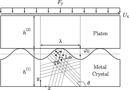
The contact problem is schematically represented in Figure . The bottom crystal has a sinusoidal surface profile, with a wavelength and an amplitude
. Each sinusoid represents a surface asperity. The top crystal has a flat surface profile. The bottom and top crystals have heights
and
, respectively, where
. Given the periodicity of the surface, a representative unit cell with wavelength
is here considered. The bottom crystal undergoes plastic deformation by edge dislocations gliding along slip planes oriented at an angle
to the x direction. Based on the two-dimensional representation of the FCC crystal structure [Citation39], three sets of slip planes are considered, oriented at
and
. These orientations are chosen to avoid alignment of the slip planes with the loading directions, which might lead to unrealistic softening of the crystal. The slip planes with the same orientation
are spaced 200 b apart.
Figure 1. Two-dimensional model of a metal single crystal with sinusoidal surface sheared by a platen that is subjected to a uniform distributed normal load . Dislocations (
) are nucleated from sources
homogeneously distributed in the bottom crystal, which contains also randomly distributed obstacles
.
3.1. Boundary conditions
An external normal force is first applied incrementally on the top surface of the platen up to(4)
where and
are the normal force rate and the uniformly distributed normal traction, respectively. Next, a uniform horizontal displacement
is applied:
(5)
Periodic boundary conditions are imposed on the lateral sides of the unit cell, . At the base of the bottom crystal
. For these two-dimensional plane strain simulations the quantities given are per unit depth of the crystals, and here the unit of depth in our variables is omitted.
4. Preliminary results: choice of the simulation cell dimensions
These simulations aim at capturing plastic deformation in the subsurface region of a large metal crystal. We performed a mesh convergence study and chose a sufficiently small mesh size such that the results converge for a given realisation. The smallest elements are required in the contact region, and have a size of about (see Figure (a)). First, we make sure that the periodic unit cell is chosen with a sufficiently large width-to-height aspect ratio to not undergo unrealistic plastic shearing from the top to the bottom. To this end, simulations are here performed for a unit cell containing an asperity with wavelength
. The responses for two different heights of the cell,
and
are then compared. The asperity amplitude is
. The platen is rigid, and has a Young modulus
; the platen modulus is sufficiently small to prevent ill-conditioning of the finite element stiffness matrix. The mean shear response is independent of the number of (periodic) unit cells simulated (not shown here). A normal force is applied incrementally on the top surface of the platen up to a value of
before applying a tangential displacement.
Figure 2. (colour online) (a) Deformed mesh plot for a body with height at
. Two identical unit cells are presented to show clearly the region where plasticity occurs. Displacements in the x direction are magnified 30 times. (b) Corresponding plastic strain distribution at the same
.
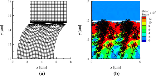
Inspection of the deformed mesh (x displacements magnified 30 times) for height in Figure (a) shows that only a region of about
underneath the contact is greatly deformed. To examine where slip occurs in the material, the corresponding plastic shear strain distribution of the bodies is presented in Figure (b). The plastic shear strain at each material point is calculated as the sum of the shear strains along each slip direction. Only the region
underneath the contact of the bottom body is shown, where more than
of the dislocations are found. Indeed, a large amount of slip occurs near the contact, indicating that the tangential force applied only shears the asperities and a small region (a couple of
in depth) beneath the surface.
Figure 3. (colour online) Tangential force against displacement
for bodies with two different heights.
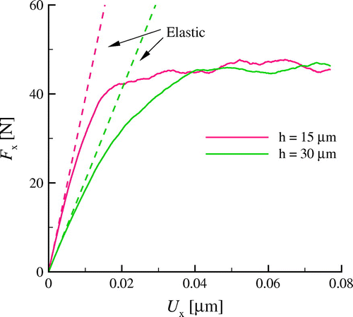
The tangential force is next shown in Figure as a function of tangential displacement
for two different crystal heights,
and
. The curves for both heights deviate from the elastic curves at small
because dislocations have already nucleated during flattening, and they are available to glide and assist in plastic shearing. This also results in a very small, non zero, tangential force at
. The curves for both heights deviate from the elastic curves at small
because dislocations are already nucleated during flattening, and they are available to glide and assist in plastic shearing [Citation36]. Initially, the tangential force
at each
is smaller for bodies with larger height but at larger displacements (
) the tangential force
levels off at approximately the same value for both heights considered.
Here, the friction coefficient is approximately 1.5. Notice that this value depends on the specific choice made for the source strength and density. This value is slightly high relative to typical coefficient values for metals ranging from 0.3 to 1.4. Lower values will be expected if interfacial slip is considered in our simulations, which now assumes fully adhesive contact. The friction coefficient
is further examined in Section 6.4.
Evidently, the plastic shear response at larger displacement is unaffected by the height of the unit cell. Therefore, in subsequent sections only deformable bodies with will be considered, to lower the computational cost.
5. Shearing with an elastic or a plastic platen
Next we investigate how the tangential force depends on whether the platen is rigid, or can deform elastically, or plastically. Sinusoidal asperities with a wavelength
and an amplitude
are considered. When the platen is elastically deformable it has Poisson ratio
and elastic modulus either
GPa, or
GPa. When it can deform plastically, both the platen and the body with sinusoidal surface have the same source density,
, and an elastic modulus of
GPa.
Figure 4. (colour online) Horizontal force against plastic displacement
for bodies with different properties. The force obtained from crystal plasticity is also included.
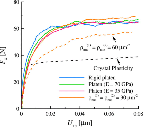
Figure shows the tangential force as a function of plastic displacement
after flattening the bodies to a normal force
. In the initial stages of shearing, i.e.
, the curves do not overlap because plasticity already occurs during flattening. At larger
, the tangential force
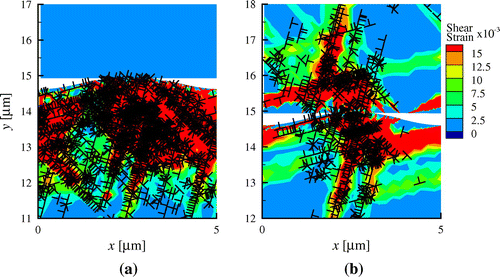
is found to be approximately the same when the platen is rigid, elastic or plastic. Evidently, the shear response does not depend on whether plasticity is confined to one body or occurs in both. The plastic shear and dislocation distributions for the elastic platen and plastic platen are shown in Figure (a) and (b).
Figure 5. (colour online) Plastic strain distribution for shearing using an elastic platen with (a) and (b) shearing both bodies, each having a source density of
, at plastic displacement
for a particular realisation.
As to be expected, increasing the source density of the bodies to decreases the tangential force
. Further increasing the source density should lead to the continuum limit, which is represented in Figure by the response obtained using the crystal plasticity model proposed by Peirce et al. [Citation40].
6. Effect of normal loading on the shear response
In the following section, we will investigate how the friction force is affected by pre-loading the bodies with different normal force . The friction force
is defined as the constant tangential force resisting relative sliding between the surfaces in contact. In this work however, there is no sliding at the contact, but only plastic flow in the material underneath the contact. Given that here after a certain
the tangential force approaches a constant value, the tangential force at displacement
is taken as the friction force.
During normal loading, the contact area and the elastic stresses induced by the normal force, as well as the plasticity generated during flattening affect the tangential force required to shear the asperities. The effect of each of these factors on the friction force is separately analysed in the following subsections.
6.1. Effect of contact area
Three different constant contact areas, and
are obtained by truncating the sinusoidal asperities with
and
at various depth from the apex.
Figure 6. (colour online) (a) Tangential force of a truncated sinusoidal surface for different contact areas A. Each vertical bar corresponds to the standard deviation of eight simulations. Plastic shear strain and dislocation distributions for a particular realisation for
(b)
and (c)
at
.
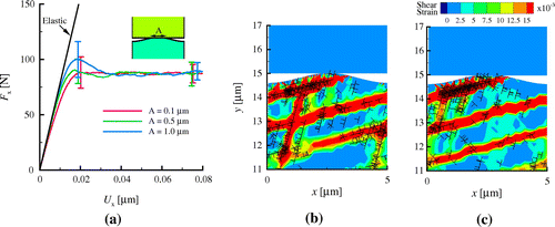
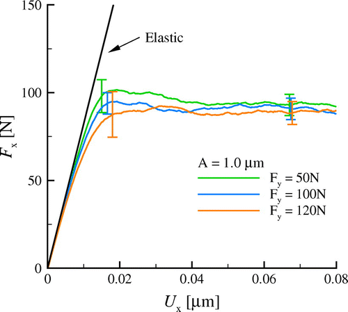
Figure (a) shows the tangential force as a function of the tangential displacement
. The elastic shear responses for the different areas are approximately the same. Apparently, the friction force
is unaffected by the size of the contact area. This is because the contact areas considered are small and much smaller than the plastic region underneath the contact. Inspection of the plastic shear strain distribution in the crystals for both
(Figure (b)) and
(Figure (c)) at
shows indeed on average, similar distinct shear bands whose dimensions are much larger than (and non related to) the contact area.
6.2. Effect of elastic flattening
To investigate the effect of elastic normal loading on the friction force, three normal forces and
are first applied on the truncated asperity surface with
before the surface is tangentially displaced. The chosen area is sufficiently large that no plasticity occurs during flattening. Figure shows that the tangential force is approximately the same for the different values of the applied normal force. Clearly, the elastic normal loading does not affect the plastic shear response of the asperities.
6.3. Effect of plastic flattening
We examine next the effect of plasticity induced during flattening on the tangential force by first loading the sinusoidal asperities with and
with a constant normal force before applying a tangential displacement. Six values for the normal force,
and
, are considered, indicated by dots in Figure (a), which gives the normal displacement
against the normal force. The increase in the tangential force
during shearing is presented in Figure (b) for the various normal loads. For normal loads
, the curves overlap, since flattening is still elastic (see Figure (a)). When the asperities are pre-loaded with a larger normal force, dislocations are nucleated during flattening, and
deviates from the elastic response at a smaller
: the tangential force also levels off at a smaller value. However, the tangential force does not further decrease when the normal force is increased from
to
.
Figure 8. (colour online) (a) Normal displacement with normal force
. The dots represent the normal force the asperities are pre-loaded with, before they are sheared. (b) Tangential force
as a function of
.
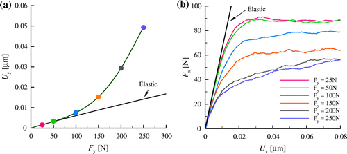
Figure 9. (colour online) Plastic strain distribution at when (a)
and (b)
, and at
when (c)
and (d)
.
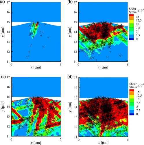
For normal force dislocations generated during flattening (see Figure (a) and (b)) assist in plastic shearing. The tangential force required to shear the asperities is therefore decreased with increasing normal force. This is evident by the smaller plastic strain in the body observed at
when
(Figure (c)) compared with when
(Figure (d)). However, when the normal force is further increased beyond
, plastic flow in the region underneath the contact caused by flattening approaches an upper limit, and therefore does not further facilitate plastic shearing of the sinusoidal asperities. This leads to approximately the same plastic slip during shear (not shown here) for
and
.
6.4. Friction force and the friction coefficient
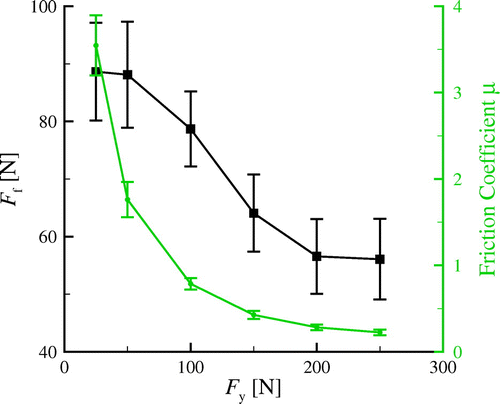
Results of the previous section are compiled in Figure to show the variation of the friction force and the friction coefficient
with the normal force. Both the friction force and the friction coefficient decrease when the normal force is increased. When the applied normal force is small, for
, the friction coefficient
obtained from our simulations is larger than typical experimental values, which range from 0.3 to 1.4 for various materials and conditions (see e.g. [Citation41]). Note that in our study perfectly adhesive conditions are assumed as we want to isolate and investigate the effect of plasticity on friction. In reality, competition exists between plastic slip in the material and slip at the asperity surface. Quantifying the effect of finite adhesion cannot be an outcome of these or any other continuum based-simulations, since the friction conditions at the interface between the two bodies can only be imposed, not emerging. In the case of finite interface adhesion, if the shear tractions here calculated are larger than the shear strength of the interface, the surfaces would slide with respect to each other, and therefore the friction coefficient would be smaller. At larger applied normal force however, the friction force becomes smaller as plastic shearing is assisted by dislocations generated during flattening. This decreases the friction coefficient to within the experimental range.
The decrease in the friction coefficient with increasing normal load is also observed in local continuum plasticity studies of static friction (e.g. [Citation14–Citation16]). However, the friction force there increases sub-linearly with the normal force, which contrasts our results. The reason for this discrepancy is that in the continuum study the contact area increases significantly with increasing normal load, determining an increase in the friction force. In the DDP simulations, the contact area increases only negligibly.
6.4.1. Local friction coefficient
Although a uniform distributed normal traction is applied on the top surface of the platen, the tangential traction
and the normal traction
at the contact are highly non-uniform, as seen in Figure (a), which shows the tractions
and
along the contact for
at displacement
.
Figure 11. (colour online) (a) Contact traction distribution in the x and y directions for
at
for a particular realisation. (b) Corresponding contact profile: the y axis is stretched independently of the x axis, and (c) the ratio
. The average value of the friction coefficient is shown using a dashed line.
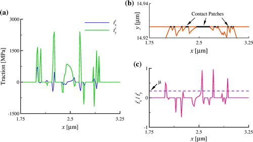
This is because the contact is patchy (Figure (b)), a consequence of the discrete nature of dislocations and slip planes [Citation34]. The local tractions can be either positive or negative, since the contact is full stick and dislocations have opposite orientation on different slip planes.
Although is, on average, smaller than
, and the average friction coefficient
is about 0.23, the local friction coefficient
can be as large as 1.0 (Figure (c)). Other realisations show similar characteristics. The average friction coefficient
is not correlated to the local friction coefficient across the contact.
The discontinuous variation of the local friction coefficient across the contact is not observed in local continuum static friction studies (see e.g. [Citation15]), where the contact area is continuous.
7. Friction force of scaled asperities
In this section, we investigate how the friction force is affected by the size of the sinusoidal asperities. Two scaled asperities having and
, both with an aspect ratio
are considered. The bodies are pre-loaded with different values of the normal force. The elastic response of the scaled asperities is identical, so that a direct comparison can be made when presenting tangential force against normal force if they are both divided by the wavelength
as in Figure (a). The mean friction force per unit wavelength of the smaller asperities is larger, especially at large
. Also, the decrease in friction force with normal force for the smaller asperities is less than for the larger. The corresponding friction coefficient
in Figure (b), is therefore larger for the smaller asperities. For instance,
for asperities with
at
is approximately 1.6 times larger than that of asperities with
.
Figure 12. (colour online) (a) Friction force per unit wavelength , and (b) corresponding friction coefficient as a function of normal force per unit wavelength
for asperity wavelengths
and
. Each vertical bar corresponds to the standard deviation of eight simulations.
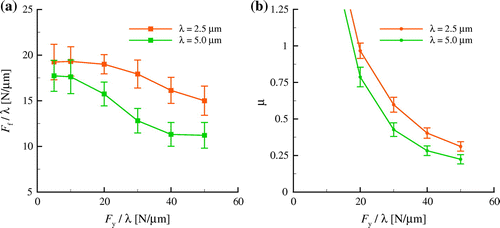
The size effect of the friction force and the friction coefficient observed in the simulations here is a result of a plasticity size effect in flattening. Deformation becomes increasingly source limited when the asperity size decreases [Citation32,Citation34,Citation35]. Plastic shear is less assisted given the smaller amount of plasticity generated in the smaller asperity during flattening, resulting in a smaller decrease in when
is increased than for the larger asperity.
8. Conclusions
Two-dimensional discrete dislocation plasticity simulations are performed to investigate the static friction response of sinusoidal surfaces in full stick contact with a platen. A normal force is first applied on the top surface of the platen before shearing starts. After an initial increase the tangential force at the contact reaches a constant value, which is here taken to be the static friction force.
Results show that the value of the friction force does not depend on whether the platen is rigid, elastic or even plastic, as long as the plastic properties of the platen are the same as those of the sinusoidal body.
The friction force is also independent of the size of the contact area, which is anyhow rather small in these simulations, below . An applied normal load has an effect on the friction force only when it is sufficiently large to induce plasticity. If this is the case the friction force decreases with the applied normal force. This is because dislocations, generated during flattening, assist in plastic shearing, which results in the decrease in the friction force when the applied normal force is increased. When plastic flow caused by flattening reaches an upper limit, increasing the normal load further no longer affects the friction force.
Given the decrease in the friction force, the friction coefficient decreases with increasing normal load. The decrease in the friction coefficient is similarly observed in experiments and local continuum plasticity studies of static friction. However, the decrease in friction coefficient in the continuum plasticity studies is caused by a sub-linear increase in the friction force with load. The increase is due to a significant increase in contact area.
The discrete dislocation plasticity simulations presented here display two other differences with the local continuum plasticity studies: (1) a discontinuous variation of the local friction coefficient along the contact, which can be up to five times larger than the average friction coefficient, and (2) the size dependence of the friction force and coefficient displayed by sinusoids with different wavelength.
Additional information
Funding
Notes
No potential conflict of interest was reported by the authors.
References
- B. Bhushan, Fundamentals of Tribology and Bridging the Gap between the Macro-and Micro/Nanoscales Vol. 10, Springer Science & Business Media, Dordrecht, 2001.
- M. Urbakh, J. Klafter, D. Gourdon, and J. Israelachvili, The nonlinear nature of friction, Nature 430 (2004), pp. 525–528.
- N.S. Tambe and B. Bhushan, Scale dependence of micro/nano-friction and adhesion of MEMS/NEMS materials, coatings and lubricants, Nanotechnology 15 (2004), pp. 1561–1570.
- E. Rabinowicz, Friction coefficients of noble metals over a range of loads, Wear 159 (1992), pp. 89–94.
- I. Etsion and M. Amit, The effect of small normal loads on the static friction coefficient for very smooth surfaces, J. Tribol. T. ASME. 115 (1993), pp. 406–410.
- U.D. Schwarz, W. Allers, G. Gensterblum, and R. Wiesendanger, Low-load friction behavior of epitaxial c 60 monolayers under hertzian contact, Phys. Rev. B 52 (1995), pp. 14976–14984.
- A. Ovcharenko, G. Halperin, and I. Etsion, Experimental study of adhesive static friction in a spherical elastic-plastic contact, J. Tribol. T. ASME. 130 (2008), p. 021401.
- Q. Chen and G.P. Carman, Microscale tribology (friction) measurement and influence of crystal orientation and fabrication process, Proceedings 13th Annual International Conference on Micro Electro Mechanical Systems, IEEE, 2000, pp. 657–661.
- D. Gourdon and J.N. Israelachvili, Transitions between smooth and complex stick-slip sliding of surfaces, Phys. Rev. E 68 (2003), p. 021602.
- L. Bureau, C. Caroli, and T. Baumberger, Frictional dissipation and interfacial glass transition of polymeric solids, Phys. Rev. Lett. 97 (2006), pp. 225501-1–225501-4.
- F.P. Bowden and D. Tabor, The nature of sliding and the analysis of friction, Proc. R. Soc. London Ser. A 169 (1939), pp. 371–391.
- S. Hyun, L. Pei, J.F. Molinari, and M.O. Robbins, Finite-element analysis of contact between elastic self-affine surfaces, Phys. Rev. E 70 (2004), p. 026117.
- R. Jedynak and M. Sułek, Numerical and experimental investigation of plastic interaction between rough surfaces, Arab J. Sci. Eng. 39 (2014), pp. 4165–4177.
- L. Kogut and I. Etsion, A static friction model for elastic-plastic contacting rough surfaces, J. Tribol. T. ASME. 126 (2004), pp. 34–40.
- V. Brizmer, Y. Kligerman, and I. Etsion, Elastic-plastic spherical contact under combined normal and tangential loading in full stick, Tribol. Lett. 25 (2007), pp. 61–70.
- I. Etsion, Revisiting the Cattaneo- Mindlin concept of interfacial slip in tangentially loaded compliant bodies, J. Tribol. T. ASME. 132 (2010), p. 020801.
- B. Luan and M.O. Robbins, The breakdown of continuum models for mechanical contacts, Nat. 435 (2005), pp. 929–932.
- J.R. Greer and W.D. Nix, Size dependence of mechanical properties of gold at the sub-micron scale, Appl. Phys. A 80 (2005), pp. 1625–1629.
- L. Nicola, Y. Xiang, J.J. Vlassak, E. Van der Giessen, and A. Needleman, Plastic deformation of freestanding thin films: experiments and modeling, J. Mech. Phys. Solids 54 (2006), pp. 2089–2110.
- D. Kiener, W. Grosinger, G. Dehm, and R. Pippan, A further step towards an understanding of size-dependent crystal plasticity: In situ tension experiments of miniaturized single-crystal copper samples, Acta Mater. 56 (2008), pp. 580–592.
- J.R. Greer and J.T.M. De Hosson, Plasticity in small-sized metallic systems: intrinsic versus extrinsic size effect, Prog. Mater. Sci. 56 (2011), pp. 654–724.
- L.C. Zhang, K.L. Johnson, and W.C.D. Cheong, A molecular dynamics study of scale effects on the friction of single-asperity contacts, Tribo. Lett. 10 (2001), pp. 23–28.
- Y. Dong, Q. Li, and A. Martini, Molecular dynamics simulation of atomic friction: a review and guide, J. Vac. Sci. Technol. A 31 (2013), p. 030801.
- E. Van der Giessen and A. Needleman, Discrete dislocation plasticity: a simple planar model, Model. Simul. Mater. Sci. Eng. 3 (1995), pp. 689–735.
- H.G.M. Kreuzer and R. Pippan, Discrete dislocation simulation of nanoindentation, Comput. Mech. 33 (2004), pp. 292–298.
- H.G.M. Kreuzer and R. Pippan, Discrete dislocation simulation of nanoindentation: the influence of obstacles and a limited number of dislocation sources, Philos. Mag. 85 (2005), pp. 3301–3319.
- X. Yin and K. Komvopoulos, A discrete dislocation plasticity analysis of a single-crystal half-space indented by a rigid cylinder, J. Appl. Mech. 78 (2011), p. 041019.
- X. Yin and K. Komvopoulos, A discrete dislocation plasticity analysis of a single-crystal semi-infinite medium indented by a rigid surface exhibiting multi-scale roughness, Philos. Mag. 92 (2012), pp. 2984–3005.
- I.A. Polonsky and L.M. Keer, Simulation of microscopic elastic-plastic contacts by using discrete dislocations, Proc. R. Soc. London, Ser. A 452 (1996), pp. 2173–2194.
- I.A. Polonsky and L.M. Keer, Scale effects of elastic-plastic behavior of microscopic asperity contacts, J. Tribol. 118 (1996), pp. 335–340.
- F. Sun, E. van der Giessen, and L. Nicola, Dry frictional contact of metal asperities: A dislocation dynamics analysis, Acta Mater. 109 (2016), pp. 162–169.
- F. Sun, E. Van der Giessen, and L. Nicola, Plastic flattening of a sinusoidal metal surface: a discrete dislocation plasticity study, Wear 296 (2012), pp. 672–680.
- L. Nicola, A.F. Bower, K.S. Kim, A. Needleman, and E. Van der Giessen, Multi-asperity contact: A comparison between discrete dislocation and crystal plasticity predictions, Philos Mag 88 (2008), pp. 3713–3729.
- K. Ng, Wei Siang and L. Nicola, Discrete dislocation plasticity analysis of contact between deformable bodies with simple geometry, Model. Simul. Mater. Sci. Eng. 24 (2016), p. 045008.
- K. Ng Wei Siang and L. Nicola, Contact between two plastically deformable crystals: A discrete dislocation dynamics study, Philos. Mag. (2016), pp. 1–17.
- F. Sun, E. Van der Giessen, and L. Nicola, Effect of plastic flattening on the shearing response of metal asperities: a dislocation dynamics analysis, J. Appl. Mech. 82 (2015), p. 071009.
- H. Song, R.J. Dikken, L. Nicola, and E. Van der Giessen, Plastic ploughing of a sinusoidal asperity on a rough surface, J. Appl. Mech. 82 (2015), p. 071006.
- L.P. Kubin, G. Canova, M. Condat, B. Devincre, V. Pontikis, and Y. Bréchet, Dislocation microstructures and plastic flow: a 3 D simulation, Solid State Phenom. 23 (1992), pp. 455–472.
- J.R. Rice, Tensile crack tip fields in elastic-ideally plastic crystals, Mech. Mater. 6 (1987), pp. 317–335.
- D. Peirce, R.J. Asaro, and A. Needleman, Material rate dependence and localized deformation in crystalline solids, Acta Metall. 31 (1983), pp. 1951–1976.
- F. Cardarelli, Materials Handbook: A Concise Desktop Reference, Springer Science & Business Media, London, 2008.

