Abstract
The magnetic configuration of a ferromagnetic system with mono-disperse and poly-disperse distribution of magnetic particles with inter-particle interactions has been computed. The analysis is general in nature and applies to all systems containing magnetically interacting particles in a non-magnetic matrix, but has been applied to steel microstructures, consisting of a paramagnetic austenite phase and a ferromagnetic ferrite phase, as formed during the austenite-to-ferrite phase transformation in low-alloyed steels. The characteristics of the computational microstructures are linked to the correlation function and determinant of depolarisation matrix, which can be experimentally obtained in three-dimensional neutron depolarisation (3DND). By tuning the parameters in the model used to generate the microstructure, we studied the effect of the (magnetic) particle size distribution on the 3DND parameters. It is found that the magnetic particle size derived from 3DND data matches the microstructural grain size over a wide range of volume fractions and grain size distributions. A relationship between the correlation function and the relative width of the particle size distribution was proposed to accurately account for the width of the size distribution. This evaluation shows that 3DND experiments can provide unique in situ information on the austenite-to-ferrite phase transformation in steels.
1. Introduction
Three-dimensional neutron depolarisation (3DND) is a powerful technique to characterise the magnetic microstructure of polycrystalline bulk materials on the (sub)micron scale [Citation1–3]. In such measurements, a polarised neutron beam interacts with the local magnetic induction in a magnetised sample, which results in a change of the polarisation vector of the neutron beam upon transmission through the (magnetised) sample. This change in polarisation is characterised by a rotation angle and by a shortening of the polarisation vector with respect to the initial polarisation. The mean magnetisation causes a net rotation of the polarisation vector and the magnetic inhomogeneities result in a decrease in polarisation. For a sample containing ferromagnetic particles (grains) in a paramagnetic matrix, the rotation angle monitors the phase fraction of the ferromagnetic phase inside the sample. The shortening of the polarisation determines magnetic correlation length, and thereby a mean magnetic particle (grain) size along the neutron beam.
This technique has successfully been used to study static and dynamic properties of magnetic microstructures in a wide range of materials such as magnetic recording materials, superconductors, amorphous metals and steels [Citation4–9]. In low-alloyed steels, the austenite-to-ferrite [Citation10] and the austenite-to-pearlite [Citation11] phase transformations have been studied using in situ 3DND measurements. In such steels, the high temperature austenite phase, which has an fcc lattice structure and is paramagnetic, transforms into ferrite with a bcc structure below a characteristic transformation temperature (A 3). Below the Curie temperature T C (=1043 K for pure Fe), the equiaxed ferritic phase becomes ferromagnetic. At a transformation temperature below the so-called A 1 temperature, the remaining austenite, being enriched in carbon, transforms into a lamellar structure composed of ferrite and cementite Fe3C plates, the so-called pearlite. In this study, we focus on the microstructure evolution for a two-phase austenite–ferrite mixture, in which the equiaxed austenite grains form the continuous parent phase and the equiaxed ferrite grains are the emerging product phase.
Key parameters to characterise the microstructure evolution during the austenite-to-ferrite transformation in steels for this magnetically inhomogeneous ferromagnetic system are the ferritic volume fraction and the ferritic particle size. Rosman and Rekveldt [Citation1] derived the theoretical framework for the determination of the magnetic phase fraction and the (spherical) particle size in the case of monodisperse ferromagnetic particles in a dilute non-magnetic medium from neutron depolarisation experiments. Te Velthuis and co-workers [Citation12] investigated the magnetic particle size obtained by neutron depolarisation and compared it to the ferrite grain size using a numerical model. The results showed that the magnetic particle size calculated from the neutron depolarisation is in good agreement (within of 10–20%) with the actual average ferrite grain size. Simultaneous measurements of the (magnetic) volume fraction and the average (magnetic) particle size by in situ neutron depolarisation measurements provide unique insight in the austenite-to-ferrite transformation in steels, as it is one of the few physical characterisation techniques known to determine both the volume fraction and the average particle size on a micron length scale in a single experiment. Such information makes it possible to separate nucleation and growth effects during the solid-state phase transformation and to reconstruct important details of the progression of this important solid-state phase transformation. However, the analysis of the 3DND data has not yet been brought to a level that makes it possible to capture not only the average ferritic particle size but also the width of the particle size distribution. The ferrite grain size distribution holds even more detailed information on the ferrite grain nucleation and growth rate and this information is crucial for accurate modelling of the austenite decomposition in low-alloyed steels during cooling. It is the aim of the present work to extend the 3DND data analysis in this direction.
To investigate the influence of the particle size distribution on the interpretation of 3DND data, we developed a model to compute the magnetic configuration for a given 3D microstructure. From this microstructure, the 3DND parameters were derived. By tuning the phase transformation parameters, the microstructure can be varied. We thereby investigated the effect of size distribution on the particle size derived from the 3DND analysis by a comparison to the mean particle size of the actual distribution. This theoretic study provides the foundation for the 3DND analysis of evolving ferromagnetic microstructures starting from a fully paramagnetic parent phase.
2. Neutron depolarisation
Two approaches have been developed to describe the neutron depolarisation due to the interaction of a polarised neutron beam with a collection of magnetic particles: (i) the Larmor and (ii) the scattering approach. Rosman and Rekveldt [Citation13] found that both approaches are fully equivalent as long as all scattered neutrons enter the analyser during the measurement. Here, we will just briefly present the neutron depolarisation in Larmor approach. A detailed overview of the neutron depolarisation theory can be found elsewhere [Citation1,2,7,13].
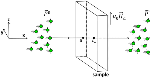
As shown in Figure , the neutron depolarisation technique measures the change of the polarisation for a polarised neutron beam after transmission through a magnetic material. The relationship between the initial polarisation vector () and the polarisation vector after transmission (
) can be expressed as
, where
is a depolarisation matrix that contains 3 × 3 elements. Generally, the depolarisation matrix can be expressed in terms of a rotation of the beam polarisation and a reduction in beam polarisation (described by a matrix
) [Citation1,2]. This reduction in beam polarisation is directly related to the field correlation matrix
of the sample volume V
W
with components α
ij
(i, j = x, y or z) :
(1)
Figure 1. (colour online) Sketch of the neutron depolarisation method shows that a polarised neutron beam () is partly depolarised (
) after transmitting through a magnetised sample subjected to an external applied magnetic field
along z direction.
where is a spatial vector, 0 is the position where neutrons enter the sample, (x, y, z) and (xʹ, y, z) are two different arbitrary points in the sample volume and
is the i-component of
that corresponds to the variation in magnetic induction with the mean magnetic induction
expressed as
(see Figure for the coordinate system). In the absence of correlations between the variations in the field components
and
(i ≠ j) along the neutron path, this correlation matrix
is diagonal. The correlation function ξ, which is proportional to the correlation length of
along the neutron beam, can be expressed as
(2)
In the absence of a net polarisation rotation, the elements of the correlation matrix and the depolarisation matrix
are related as:
(3)
where δ
ij
is the Kronecker delta, c
1 = 2.15 × 1029
λ
2 T
−2 m−4 with λ the neutron wavelength and L
w
is the sample length along the neutron beam. Rosman and Rekveldt [Citation13] showed that in the Fourier space, is directly related to the magnetisation of the sample
:
(4)
where , μ
0 is the permeability of vacuum,
is the reciprocal lattice vector and
its unit vector. As described in Ref. [Citation12], for a distribution of uncorrelated ferromagnetic particles, the diagonal elements of the matrix
have the following analytical solutions:
(5)
(6)
(7)
where f is the volume fraction of the ferromagnetic phase, is the reduced magnetisation scaled to the saturation magnetisation M
s of the ferromagnetic phase,
is a constant and R is the radius of the ferromagnetic particle. According to Equation (Equation2
(2) ), the correlation function ξ then corresponds to
(8)
where and c
3 is a constant that depends on the shape, orientation and spatial distribution of the ferromagnetic particles. For identical spheres, this constant is
. Equation (Equation8
(8) ) shows that ξ depends on the ratio of the higher order averages of the particle sizes, which suggests that ξ includes the information of both the average particle radius
and the spread in radius. By writing
and assuming
, Equation (Equation8
(8) ) is transformed to give the relationship between δ and ξ:
(9)
These equations show that one can derive the neutron depolarisation parameters , ξ and
by computing the orientation of the magnetic moments for all magnetic particles in a particulate system. Furthermore, the characteristic particle size δ can be obtained with Equation (Equation9
(9) ) from the magnetic correlation length. In a 3DND measurement, one measures the transmission of the polarisation components to derive the depolarisation matrix
and then calculate f and δ [Citation10,11]. However, it should be noted that several approximations have been made in the derivation of Equation (Equation9
(9) ). The goal of the present work is to evaluate how the particle size distribution influences the analysis of the neutron depolarisation data and how large the potential deviations are for our system of interest in the case of ferrous phase transformations.
3. Microstructural magnetic model
The present model was developed on the basis of the austenite–ferrite microstructural model by Te Velthuis and co-workers [Citation12] in which spherical (ferromagnetic) ferritic particles nucleate and grow in a fully (paramagnetic) austenitic microstructure that is generated by a Voronoi construction. A given 3D microstructure with a preset ferrite size distribution was generated first and its magnetic configuration was computed. The resulting 3DND characteristics were then calculated using Equations Equation(4)–(7). After the 3DND parameters were obtained, Equation (Equation9(9) ) was used to back calculate the magnetic particle size, which should be identical to the given particle size if all the used approximations are valid. Otherwise, a deviation will be generated, which can be evaluated subsequently. The present work is generic in nature, but has been applied to the magnetic microstructure evolution during the austenite–ferrite phase transformation in steels. In this phase transformation, the high-temperature austenite phase is nonmagnetic (paramagnetic), while the low-temperature ferrite phase is magnetic (ferromagnetic) below the Curie temperature T
C [Citation10–12].
To start the simulations, a 3D microstructure comprising a nonmagnetic phase and a magnetic phase was created in a cubic box with a length L
b
. The magnetic particles are assumed to be spherical and centred at the grain corners of the nonmagnetic phase, as discussed in [Citation14]. For the austenite–ferrite microstructure in low-alloyed steels, the parent austenite grain corners, edges and surface are the preferred nucleation sites for the ferrite particles [Citation15]. For isothermal transformations at a low undercooling or for transformations at a slow continuous cooling, austenitic grain corners are the most probable sites for the nucleation of ferrites [Citation16,17]. The geometry of the ferrite particles depends largely on the specific transformation conditions. Although ferrite can grow into allotriomorphic plate-like particles along grain boundaries [Citation18–20], most experimental [Citation17] and modelling [Citation21,22] studies showed relatively isotropic equiaxed ferrite in the early stages of the phase transformation when coalesce of particles has not yet appeared. In the present modelling, the geometry of the magnetic particles has been simplified to a spherical shape as this shape is close to the most frequently observed equiaxed ferrite particles. The collection of the magnetic particles closely resembles a log-normal size distribution. Each magnetic particle is then assigned with a radius, a spatial location and a randomly chosen magnetic anisotropy (referred to as the easy axis). The magnetisation of each magnetic particle is assumed to be homogeneous with a magnitude M
s
and an orientation
. The orientation for each magnetic particle was computed by extending the original Stoner–Wohlfarth model [Citation23] to include the mean field and the magnetic interaction with neighbouring particles. To compute the magnetic configuration, the total energy of all magnetic particles is minimised.
For a domain i, the local field is the summation of the applied field
, the total magnetic dipole field
(sum over j) and the mean field
:
(10)
where α is the mean field parameter [Citation24], which has a fixed value of α = 1/3 in the present study. The magnetic dipole field accounts for the total field originating from all neighbouring magnetic particles [Citation25]. The dipole field for particle i from another particle j is expressed as(11)
where is the displacement vector from particle j to i,
is the magnetisation and V
j
is the volume of particle j. When the magnitude of the dipole field H
d,ij
(which depends on r
ij
and V
j
) becomes smaller than 0.5% M
s
, it is considered to be negligible and is ignored in the calculations. This threshold corresponds to: r
ij
/(3V
j
/4π)1/3 > 5.2.
The magnetic energy E
i
of a particle i is the sum of the magnetostatic energy E
H,i
and the anisotropy energy E
a,i
(12)
with E
H,i
= −μ
0
H
l,i
M
s
cosφ
i
and , where φ
i
is the angle between
and
, θ
i
is the angle between
and the easy axis and N
s
is the shape anisotropy factor, chosen to be N
s
= 0.1 to reflect the sample geometries used in the ND experiments. To derive the minimum of E
i
expressed in Equation (Equation12
(12) ), one can get a unique solution for φ
i
by applying the constraints
and
[Citation26]. Once the minimum energy is derived for all particles, the total energy of the whole system is calculated and compared to the one derived in the previous calculation until the difference between them is less than 0.5%. By this iterative process, a stable magnetic configuration can be achieved. The mean magnetisation
, the reduced magnetisation m and the values of
are calculated in the same way as in [Citation12].
The 3DND parameters are then calculated as a function of applied magnetic field from the computed magnetic configuration. The magnetic particle size δ
ND
is estimated from the 3DND data with Equation (Equation9(9) ) and compared to the known structural particle size δ
s
derived from the computed magnetic microstructure. To study the influence of grain size distribution, computations are carried out for a series of given microstructures, composed of (paramagnetic) austenite and (ferromagnetic) ferrite, that evolved as a function of temperature [Citation14]. The saturation magnetisation of ferrite M
s is calculated with the formula proposed by Arrott and Heinrich [Citation27]. The starting austenite structure is generated in a cubic box with L
b
= 70 μm containing quasi-isotropic austenite grain cells with an average diameter of d
γ
= 20 μm and a minimum value of d
min
= 12 μm constructed via a conventional Voronoi construction method. The ferrite is generated at the corners of the austenite grains and allowed to grow isotropically once nucleated, resulting in a ferrite grain number density ρ
α
, volume fraction f, average grain radius
and a standard deviation σ. The ferrite grain size distribution is produced in such a way that both f and
are kept constant, whilst ρ
α
is adjusted to ensure a constant ratio of
.
4. Results and discussion
4.1. Influence of the size distribution
Figure (a) shows the microstructure generated for f = 0.10, ρ
α
= 2.45 × 10¹⁴ m−3, R = 4.4 μm and σ/R = 0.25 and the corresponding magnetisation for each particle. By representing the particles by magnetic dipoles (of strength with V the volume of the particle) located at their centres, we can directly visualise the orientations of the magnetisation for each particle at different applied fields, as shown in Figure (b).
Figure 2. (colour online) (a) 3D visualisation of the microstructure with f = 0.10, ρ
α
= 2.45 × 10¹⁴ m−3, = 4.4 μm and σ/R = 0.25 and (b) the computed magnetisation for each particle illustrated by the orientation of the arrows with easy axis shown in dashed lines. (c) The calculated <m
x
>, <m
y
> and <m
z
> as a function of the applied field (arrows indicate the changing direction of applied field) for a magnetic hysteresis loop.
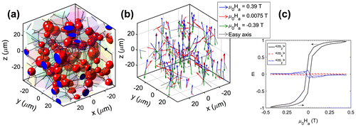
At a positive field of μ
0
H
a
= 0.39 T, the of all particles tend to incline towards the direction of the applied field. However, due to the magnetic interactions of the particles, the local magnetisation inside the particles is not perfectly aligned, which results in <m
z
> = 0.97 (with <m
x
> ≈ <m
y
> ≈ 0). When μ
0
H
a
decreases to 0.0075 T, the local magnetisation shows more orientational disorder resulting in <m
z
> = 0.57. When μ
0
H
a
is reversed to −0.39 T, most magnetisation vectors rotate to align with the negative applied field. As shown in Figure (c), the overall change in magnetisation shows a magnetic hysteresis loop. As in the actual 3DND experiment, the magnetic field is aligned along the z-axis the magnitude of <m
x
> and <m
y
> is expected to be very small. We will therefore only focus on <m
z
> in the remainder of the analysis.
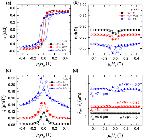
The first calculation was done for different microstructures with a fixed magnetic fraction f. Table gives the configuration of the magnetic microstructure with f = 0.10 for different values of . Figure shows the characteristic 3DND parameters: the rotation angle φ, the determinant of depolarisation matrix
, the correlation function ξ and the particle radius δ
ND
as a function of the applied field. By increasing
from 0 to 0.25, the curves for φ hardly change. Only when
is increased to 0.50, the hysteresis increases and the saturation levels decreases. The value of
is more sensitive to σ/R as it probes the variations in local magnetic induction. As shown in Figure (b), the magnitude of
decreases with increasing
. This indicates that for identical values of f and
, the polarisation is reduced more strongly when the spread in size distribution increases. The lowest values for
are observed for the smallest applied fields (|μ
0
H
a
| < 0.1 T), whereas a saturation is found for higher applied fields. In Figure (c), the corresponding values for the magnetic correlation function ξ are shown. As ξ probes the product of the correlation length and the average variation in magnetic induction
, a more disordered magnetic configuration present at small applied fields (as shown in Figure (b)) results in a bigger value of ξ. Figure (d) compares δ
ND
to δ
s
. A very good consistency is found for the whole range of applied fields, although a small but growing deviation is found for increasing values of
.
Table 1. The configuration of the ferrite microstructure at an identical magnetic fraction.
Figure 3. (colour online) Derived 3DND parameters as a function of the applied field μ
0
H
a
for microstructures with a constant magnetic fraction f = 0.10 and different values of the distribution width : (a) rotation angle φ, (b) determinant of depolarisation matrix
, (c) correlation function ξ and (d) average particle radius δ
ND
. In (d), the average particle radius δ
s
calculated directly from the microstructures computationally generated is plotted as solid lines.
4.2. Influence of the volume fraction
Figure shows the characteristic 3DND parameters as a function of the applied field for different magnetic fractions f with a constant relative distribution width of = 0.25. It can be seen from Figure (a) that the value of f indeed has a significant effect on the rotation angle φ as the saturation level roughly scales with the magnetic fraction. Similarly, the saturation level of
is very sensitive to the magnetic fraction (see Figure (b)) in comparison with the effect of varying
(see Figure (b)). It is interesting to note that for f = 0.05, the derived
shows a negligible dependence on the applied field. However, the sensitivity of
to the applied magnetic field increases significantly for increasing values of f. For increasing values of f
, the difference between δ
ND
and δ
s
becomes more pronounced. At small applied fields, δ
ND
underestimate δ
s
, whereas at higher fields δ
ND
is larger than δ
s
.
Figure 4. (colour online) Derived 3DND parameters as a function of the applied field μ
0
H
a
for microstructures with a constant f
= 0.25 and different values of the magnetic fraction f: (a) rotation angle φ, (b) determinant of depolarisation matrix
, (c) correlation function ξ and (d) average particle radius δ
ND
. For comparison in (d), the average particle radius δ
s
calculated directly from the microstructure is shown as solid lines.
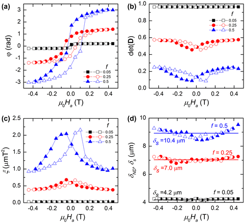
Similar results for ξ as a function of applied field are found for a value of constant σ/R (Figure (c)) and a constant value of f (Figure (c)). As the magnetic fraction f increases, the effect of magnetic inter-particle interactions becomes more pronounced, resulting in an increasing hysteresis.
4.3. Determination of the particle size
The simulations of Figures and show that an increase in the width of the particle size distribution enhances the difference between δ
ND
and δ
s
. The main reason for this difference is that magnetic correlations were assumed to be negligible when Equations Equation(5)–(9) were derived. However, in the present numerical calculations, these magnetic correlations are explicitly included. In addition, parameter in Equations (Equation8
(8) ) and (Equation9
(9) ) has been derived for identical spheres, but was applied for poly-dispersed spheres.
Figure 5. (colour online) Comparison between the particles radius δ
ND
derived by an 3DND analysis and the actual particle radius δ
s
for different size distributions with = 0, 0.25 and 0.50 as a function of the magnetic fraction f at applied fields ranging from −0.39 to +0.39 T.
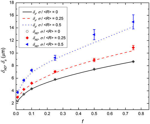
In Figure , a comparison between δ
ND
and δ
s
as a function of f is made for different values of at applied magnetic fields ranging from −0.39 to + 0.39 T. In general, δ
ND
is in good agreement with δ
s
over the range of magnetic fractions and size distributions studied. However, the difference increases with increasing f and
. As explained earlier, this difference is mainly attributed to the limited validity of the assumptions made in the original 3DND analysis. As can be seen in Figure , the maximum difference between δ
ND
and δ
s
is about 13%, which is satisfactory for most experiments. Based on this analysis, it was possible to deduce the number density ρ of magnetic particles. A simple relation based on the assumption of identical spherical particles yields ρ = 3f/4πδ
3 with an estimated number density that is found to be within a factor 5 compared to the real magnetic particle number density.
To accurately determine the average particle size, an accurate relationship between ξ and δ is required. Te Velthuis and co-workers [Citation12] analysed the dependence of ξ on the magnetic configuration. They generalised Equation (Equation8(8) ) as:
(13)
In the previous analysis, the constants were equal to a 1 = 3/4 and a 2 = 4/3(4πf 2 /81). In their numerical study, it was found that the parameters a 1 and a 2 were sensitive to (1) the ferrite grain size distribution and (2) the spatial homogeneity of the ferrite grains.
Since the analytical solution of Equation (Equation4(4) ) was derived for mono-disperse particle distributions, it is not straightforward to include the effect of the size distribution on ξ. An alternative approach is to compare the numerical results for poly-disperse particle distributions to those for identical particles to investigate its influence. To this aim, we calculated the ratio of ξ(σ)/ξ(0) for different values of f. The results show that ξ(σ)/ξ(0) is nearly independent of both the applied field and the magnetic fraction f at a fixed value of σ/R. However, ξ(σ)/ξ(0) increases with increasing σ/R. When we plot the parameter ξ(σ)/ξ(0) as a function of
, as shown in Figure , a power law dependence
with p = 2 is observed for
≤ 0.5. This relation suggests that the effect of the size distribution on ξ can be described by an additional factor. We can therefore conclude that the relation
(14)
Figure 6. (colour online) Normalised field correlation function ξ (σ)/ξ (0) as a function of . The solid line shows the fit to the relationship
for
≤ 0.5.
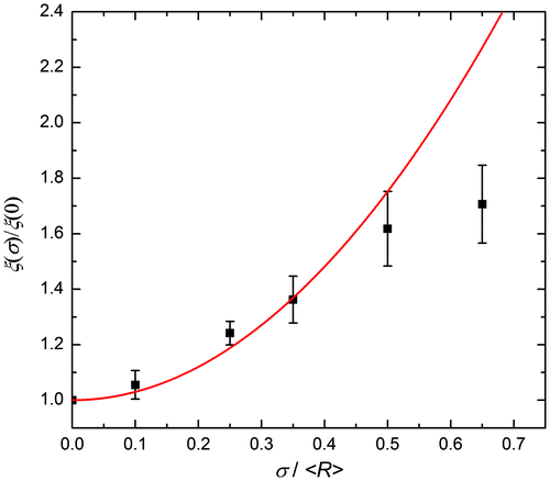
with χ = 3.0(3) can be used to describe the correlation function for poly-disperse particle size distributions. The variable ξ(0) can be calculated with Equation (Equation8(8) ). The newly derived equation (Equation14
(14) ) is now a very useful addition to analyse experimental 3DND data. For an identical particle system (mono-disperse), the average particle size can be calculated with Equation (Equation9
(9) ). For a poly-disperse system, ξ(σ > 0) can be expressed as a function of
with Equation (Equation14
(14) ), as shown in Figure . The effective size δ can then be calculated with Equation (Equation9
(9) ). Since δ now directly depends on
, the additional relation of Equation (Equation14
(14) ) provides an accurate estimate for δ. For a lognormal distribution
, one can derive the moments of the radius
and
. Combining these relations yields
. For σ/R ≪ 1, this results in
, which is fully consistent with the fitted relationship shown in Figure . Hence, the relationship between ξ(σ)/ξ(0) and σ/R found in the present study is suitable to determine both the particle size and the width of the size distribution, particularly for σ/R ≤ 0.5. The average particle size now corresponds to
.
In the above simulations, the value of σ/R is set as a constant. During the austenite-to-ferrite phase transformations in steels, σ/R is found to vary between 0 and 0.7 [Citation14,28], but once nucleation is completed σ/R tends to fluctuate around a constant value. This behaviour simplifies the above 3DND analysis to obtain a reliable experimental estimate of the magnetic particle size (ferrite grain size) and size distribution during phase transformations in steels. The newly established relationship between ξ(σ > 0) and ξ(σ = 0) thereby sheds new light on the analysis of size distributions of magnetic particles from the 3DND data. It should be noted that the geometry of the ferrite particles has been simplified in the present modelling to a spherical shape. Under most conditions, the simplified geometry used here reflects the ferrite growth reasonably well in the initial stages of the transformation. The conclusions drawn from this study are thereby very useful to link the 3DND parameters to the microstructural characteristics.
5. Conclusions
We have computed magnetic configurations for magnetic microstructures with mono- and poly-disperse magnetic particles in 3D space and translated those to the characteristic 3DND parameters. The correlation function and the determinant of the depolarisation matrix are found to be very sensitive not only on the magnetic phase fraction and average particle size, but also on the particle size distribution. The correlation function increases with increasing volume fractions and with the width of the particle size distribution of the magnetic particles. The magnetic particle size derived from 3DND data is found to be in very good agreement with the computed microstructural particle size over a wide range of volume fractions and grain size distributions. Deviations in the estimated particle size from 3DND data are found to originate from the spread in particle size. A relationship between the field correlation function and the relative width of the particle size distribution is found that accurately describes the deviations. The present simulations shed new light on the analysis of 3DND data from magnetic particle systems with a poly-disperse particle size distribution and are extremely useful to deepen the analysis of the austenite–ferrite transformation in low-alloyed steels.
Disclosure statement
No potential conflict of interest was reported by the authors.
Acknowledgements
The authors appreciate many clarifying discussions with Dr Theo Rekveldt. Haixing Fang is grateful to the financial support provided by the China Scholarship Council (CSC).
References
- R. Rosman and M.T. Rekveldt , Neutron-depolarization theory in particulate media , Phys. Rev. B 43 (1991), pp. 8437–8449.10.1103/PhysRevB.43.8437
- M.T. Rekveldt , N.H. van Dijk , S.V. Grigoriev , and W.G. Bouwman , Three-dimensional magnetic spin-echo small-angle neutron scattering and neutron depolarization: A comparison , Rev. Sci. Instr. 77 (2006), pp. 073902.10.1063/1.2204579
- A. Kumar , Magnetic correlations at domain/cluster length scales using neutron depolarization , Proceedings of the sixth conference on neutron scattering, 21–23 Nov. 2016, Mumbai, India.
- M.T. Rekveldt and F.J. van Schaik , Static and dynamic neutron depolarization studies of ferromagnetic domain structures , J. Appl. Phys. 50 (1979), pp. 2122–2127.10.1063/1.327079
- S. Mitsuda and Y. Endoh , Neutron depolarization studies on magnetization process using pulsed polarized neutrons, J. Phys. Soc. Jpn. 54 (1985), pp. 1570–1580.10.1143/JPSJ.54.1570
- I. Mirebeau , S. Itoh , S. Mitsuda , T. Watanabe , Y. Endoh , M. Hennion , and R. Papoular , Neutron depolarization in a reentrant spin-glass system: Amorphous Fe-Mn , Phys. Rev. B 41 (1990), pp. 11405–11416.10.1103/PhysRevB.41.11405
- R. Rosman and M.T. Rekveldt , Neutron depolarization in particulate media: A review of theory and experimental results , J. Magn. Magn. Mater. 95 (1991), pp. 319–340.10.1016/0304-8853(91)90228-3
- Ö. Çakr , M. Acet , M. Farle , and A. Wilders , Magnetic correlations in the magnetocaloric materials Mn3GaC and Mn3GaC0.85N0.15 studied by neutron polarization analysis and neutron depolarization , J. Phys. Condens. Matter. 28 (2016), p. 13LT02.
- K. Manna , D. Samal , A.K. Bera , S. Elizabeth , S.M. Yusuf , and P.S. Anil , Kumar, Correspondence between neutron depolarization and higher order magnetic susceptibility to investigate ferromagnetic clusters in phase separated systems , J. Phys. Condens. Matter 26 (2013), p. 016002.
- S.G.E. te Velthuis , N.H. van Dijk , MTh Rekveldt , J. Sietsma , and S. van der Zwaag , Field-dependent neutron depolarization of the ferrite formation in medium-carbon steels , Acta Mater. 48 (2000), pp. 1105–1114.10.1016/S1359-6454(99)00414-0
- S.E. Offerman , L.J.G.W. van Wilderen , N.H. van Dijk , M.Th. Rekveldt , J. Sietsma , and S. van der Zwaag , In-situ study of pearlite nucleation and growth during the isothermal austenite decomposition in nearly eutectoid steel , Acta Mater. 51 (2003), pp. 3927–3938.10.1016/S1359-6454(03)00217-9
- S.G.E. te Velthuis , N.H. van Dijk , M.T. Rekveldt , J. Sietsma , and S. van der Zwaag , Domain size determination of granular ferromagnetic systems with neutron depolarization , J. Appl. Phys. 89 (2001), pp. 1275–1280.10.1063/1.1332090
- R. Rosman and M.T. Rekveldt , Neutron depolarization theory in the Larmor and the scattering approach , Z. Phys. B Condens. Matter 79 (1990), pp. 61–68.10.1007/BF01387826
- H. Fang , M.G. Mecozzi , E. Brück , S. van der Zwaag , and N.H. van Dijk , Analysis of the grain size evolution for ferrite formation in Fe-C-Mn steels using a 3D model under a mixed-mode interface condition, Metall. Mat. Trans. A 49 (2018), pp. 41–53.10.1007/s11661-017-4397-y
- M. Enomoto and H.I. Aaronson , Nucleation kinetics of proeutectoid ferrite at austenite grain boundaries in Fe-C-X alloys , Metall. Mater. Trans. A 17 (1986), pp. 1385–1397.10.1007/BF02650120
- W. Huang and M. Hillert , The role of grain corners in nucleation , Metall. Mater. Trans. A 27 (1996), pp. 480–483.10.1007/BF02648428
- M. Militzer , R. Pandi , and E.B. Hawbolt , Ferrite nucleation and growth during continuous cooling , Metall. Mater. Trans. A 27 (1996), pp. 1547–1556.10.1007/BF02649814
- E. Gamsjäger , M. Militzer , F. Fazeli , J. Svoboda , and F.D. Fischer , Interface mobility in case of the austenite-to-ferrite phase transformation , Comp. Mater. Sci. 37 (2006), pp. 94–100.10.1016/j.commatsci.2005.12.011
- E. Gamsjäger , R.E. Werner , W. Schiller , and B. Buchmayr , Kinetics of the austenite-to-ferrite phase transformation – Simulations and experiments, Steel Res. Int. 85 (2014), pp. 131–142.10.1002/srin.v85.2
- E. Gamsjäger , M. Wiessner , S. Schider , H. Chen , and S. van der Zwaag , Analysis of the mobility of migrating austenite-ferrite interfaces , Philos. Mag. 95 (2015), pp. 2899–2917.10.1080/14786435.2015.1082662
- Y.J. Lan , D.Z. Li , and Y.Y. Li , Modeling austenite decomposition into ferrite at different cooling rate in low-carbon steel with cellular automaton method , Acta Mater. 52 (2004), pp. 1721–1729.10.1016/j.actamat.2003.12.045
- M. Militzer , M.G. Mecozzi , J. Sietsma , and S. van der Zwaag , Three-dimensional phase field modelling of the austenite-to-ferrite transformation , Acta Mater. 54 (2006), pp. 3961–3972.10.1016/j.actamat.2006.04.029
- E.C. Stoner and E.P. Wohlfarth , A Mechanism of magnetic hysteresis in heterogeneous alloys, Philos. Trans. R. Soc. London Ser. A 240 (1948), pp. 599–642.10.1098/rsta.1948.0007
- D.C. Jiles and D.L. Atherton , Theory of ferromagnetic hysteresis , J. Magn. Magn. Mater. 61 (1986), pp. 48–60.10.1016/0304-8853(86)90066-1
- J.D. Jackson , Classical electrodynamics , 3rd ed., Wiley, New York, 1999.
- B.F. Phelps , F. Liorzou , and D.L. Atherton , Inclusive model of ferromagnetic hysteresis , IEEE Trans. Magn. 38 (2002), pp. 1326–1332.10.1109/20.996018
- A.S. Arrott and B. Heinrich , Application of magnetization measurements in iron to high temperature thermometry , J. Appl. Phys. 52 (1981), pp. 2113–2115.10.1063/1.329634
- M.G. Mecozzi , M. Militzer , J. Sietsma , and S. van der Zwaag , The role of nucleation behavior in phase-field simulations of the austenite to ferrite transformation, Metall. Mater. Trans. A 39 (2008), pp. 1237–1247.10.1007/s11661-008-9517-2
