ABSTRACT
Generation and accumulation of atomic vacancy due to pair annihilation of edge dislocations during plastic slip deformation of metallic materials are numerically evaluated by crystal plasticity analysis. Dislocation density-based models are utilised in the deformation analysis and a theoretical model for the generation of atomic vacancies is introduced. Purely uniform single- and double-slip deformations are analysed and results show that the evolution of the vacancy density depends largely on the microstructure length scale and multiplication of slip activity on different slip systems.
1. Introduction
Atomic vacancies are one of the point defects in crystal lattice and considered to have significant effects on the physical behaviour of metallic materials. Thermally equilibrium density of the vacancy in, for example, copper at room temperature is at the order of 107 m−3 and its concentration is smaller than 10−20, while excess vacancies are introduced by various mechanisms such as the irradiation of energy particles, pair annihilation of edge dislocations, movements of grain boundaries, climb of dislocation and others. Vacancy concentration in Fe deformed 20% at room temperature was reported to be at the order of 10−5 [Citation1], which is obviously far beyond the thermal equilibrium concentration. There have been a wide variety of studies on the effect of excess vacancies on diffusion [Citation2,Citation3], nucleation of precipitate [Citation4], recrystallisation [Citation5], movement of grain boundaries [Citation6,Citation7], creep deformation [Citation8], generation of nano-voids [Citation9–11], fatigue crack initiation in persistent slip bands [Citation12–15] and strain localisation and plastic instability [Citation16–18]. Interactions between hydrogen and vacancy [Citation19,Citation20], or hydrogen–vacancy complex and dislocations [Citation21] are other points of current discussion. Among the above-mentioned studies, various roles of the vacancy are pointed out; however, quantitative discussions on the density or the concentration of vacancies are less explored. Two most common methods to evaluate the vacancy density are the measurement of positron annihilation lifetime where positron resides longer time near the vacancy site and the measurement of electric resistance, whereas the output of this measurement is limited to the average of the vacancy density in the material. Density distribution of atomic vacancy in the microstructure of metallic materials under a wide range of deformation condition is a point of interest from a variety of phenomenon in metal physics. In this study, we study numerically the generation and accumulation of excess vacancies due to plastic slip deformation.
Movement of dislocations realises plastic slip deformation of metallic materials. Dislocations accumulate and annihilate during the plastic deformation and a numerous amount of atomic vacancies are supposed to be generated due to pair annihilation of edge dislocations with positive and negative signs. Essmann and Mughrabi [Citation22] proposed a model for the density evolution of atomic vacancy due to pair annihilation of edge dislocations during slip deformation as follows:(1) where N, Z,
, D and γ denote the numbers of atoms and vacancies in unit volume, magnitude of the Burgers vector, dislocation annihilation distance and plastic shear strain, respectively.
and ce denote the accumulated density of edge dislocations and the ratio of contribution from the edge component to the plastic shear strain, respectively. Moving dislocations are assumed to sweep up vacancies located within a distance yp above and below the glide plane. The density
is considered to be the statistically stored dislocations (SSDs) but not the geometrically necessary dislocations (GNDs) because the density of GNDs originates from the excess of the Burgers vector and individual dislocations are assumed not to be able to find its opponent to annihilate. Essmann and Mughrabi [Citation22] showed saturation values of vacancy for some extreme cases but not their evolution. In this study, we evaluate the evolution of vacancy density by integrating the model by using some additional models for the crystal plasticity analysis.
2. Accumulation and annihilation of the SSDs and a modified model for the evolution of vacancy density
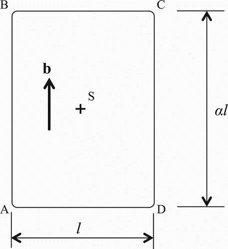
Let us assume that a rectangular-shaped dislocation loop ABCD is emitted from a dislocation source S as shown in . If the dimension of the accumulated loop is l × αl, then the average of the travel distance of the edge and screw segments L is given by(2) where α could be related to the ratio of average velocities of screw and edge segments. There could be a variety of forms in the emission of dislocation loops in the microstructure and we assume that the loop emission shown in is a representative one and call L as the dislocation mean free path. Increment of the accumulated dislocation density is connected to the increment of plastic shear strain as follows [Citation23]:
(3) where n denotes the slip system number and
and
denote the increments of the dislocation density and plastic shear strain on the slip system n, respectively. The dislocation density evaluated by Equation (3) is the density of the SSDs and the subscript S express this. Annihilation of accumulated dislocations is introduced through the model of Kocks and Mecking [Citation24–26] as follows:
(4) where the annihilation distance D will depend on temperature, strain rate, stress state, microstructure length scale and other factors.
Figure 1. Emission of a rectangular-shaped dislocation loop with aspect ratio α. S and b show the dislocation source position and the Burgers vector, respectively.
Let us define the model for the dislocation mean free path as a function of state variables as follows [Citation27,Citation28]:(5) where c* and d* are a numerical factor and a microstructure length scale, respectively. Equation (5) defines the mean free path as a function of dislocation density and microstructure length scale and Equation (2) describes the geometrical aspects of accumulated loops.
denotes the density norm of the GNDs on the slip system m; however, the strain gradient and GNDs are not discussed in this paper but discussed elsewhere [Citation29–33]. w(nm) gives the weight of contribution from dislocations accumulated on slip system m to the mean free path on the slip system n. In this paper, we assume w(nm) is zero when n and m are co-planer or n = m, and otherwise, w(nm) = 1. The function Min[… , …] selects smaller values from the two arguments. The first argument in Equation (5) gives the average spacing of the forest dislocations multiplied by c*, and this could be called the effective spacing of forest dislocations. The interaction intensity of moving and forest dislocations is controlled by c* [Citation34]. Therefore, the model given by Equation (5) defines the dislocation mean free path by the effective spacing of the forest dislocations when the microstructure length scale d* is larger than the spacing, while the microstructure length scale defines the mean free path when it is smaller than the effective spacing of the forest dislocations.
We slightly modify the model for the increment of atomic vacancy given by Equation (1) as follows:(6)
(7) where dN(n) denotes the increment of vacancy by plastic slip on the slip system n. The first and second terms in parenthesis on the right-hand side of Equation (6) give the increment by the pair annihilation of edge dislocations and decrement by the dislocation sweep, respectively. We numerically integrate the increment of vacancy density on slip systems by Equation (6) and evaluate the total density
by Equation (7). Contribution from individual slip systems is identified and if slip takes on multiple systems, dislocation sweeps take effect not separately but by the total density.
It is shown in that the edge dislocation segment AD grows from the source S and sweeps the triangular area ASD. Similarly, the screw segment CD sweeps the area DSC and these two areas have the same value. This means that the contribution of the edge segment to the plastic shear strain is equal to the contribution from the screw component. Therefore, ce = 0.5 regardless of the aspect ratio of the accumulated dislocation loops. Separation of edge component from the SSD density is straight forward and given by the following equation:(8)
3. Basic equations for the crystal plasticity finite element analysis
Critical-resolved shear stress for the slip system n is given by the following model [Citation27,Citation35]:(9) where the first, second and third terms on the right-hand side give the lattice friction, Taylor hardening and Orowan stress, respectively. The lattice friction is considered to depend on temperature but not to vary with deformation.Footnote1 In the Taylor hardening term, accumulation of SSDs on slip systems m (m = 1, …) contributes to the hardening of the slip system n via the interaction matrix
. The diagonal component of the interaction matrix is unity and off-diagonal components are 1.01 + ε, where ε is a random number smaller than 10−4. By this setting of the interaction matrix, strain hardening of slip systems is approximately isotropic and at the same time, multiple slip deformation is traceable without numerical singularity. a and μ denote numerical coefficient and elastic shear modulus. a = 0.1 is assumed in this paper. The third term adds the resistance from grain boundaries or other obstacles to the movement of dislocations and d gives another representative length scale of the microstructure. β is considered to be a constant and β = 1 in this paper.
Constitutive equation for the plastic slip deformation by Hill,(10) is used in the numerical analysis.
,
and
are increments of stress, strain and elastic constants, respectively.
is the Schmid tensor and defined as follows:
(11) where
and
are unit vectors parallel to the slip direction and slip plane normal of the slip system n, respectively. Strain hardening parameter
is obtained from the dislocation density-based models as follows:
(12)
4. Models employed for the analysis
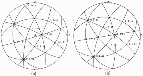
Let us assume Cu single crystal models where there is neither inhomogeneity nor substructure. Magnitude of the Burgers vector is 2.556 × 10⁻¹⁰ m and the number density of atoms Z = 8.469 × 1028 m−3. The initial vacancy concentration is assumed to be zero. The initial dislocation density on 12 slip systems of {111}⟨110⟩ is 109 m−2 and the total of the initial dislocation density is 1.2 × 10¹⁰ m−2. Aspect ratio α = 1 is assumed for the dislocation loops. The lattice friction θ0(n) = 0.5 MPa (n = 1, 2, … , 12). Two crystal orientations are used; one is for single and the other is for double-slip orientation. shows two orientations. We apply a uniform tensile load to the models and uniform slip deformation takes place. Therefore, there is no need to employ the finite element technique; however, we utilised a software code and implemented the model for the evolution of atomic vacancy and run by using a few number of finite elements.
Figure 2. Crsytal orientations for single- (a) and double- (b) slip conditions. Uniform tensile load in y direction is applied.
summarises parameters used for models employed in this paper. is 5 or 25 assuming a typical [Citation17] and extended range of pair annihilation. A typical range of dislocation sweep is considered to be equal to the magnitude of the Burgers vector [Citation22]. Various values of
are tested. c* is 15 or 100 in this paper and the microstructure length scales of d and d* are assumed to be the same and 1000, 20 or 1 μm are used for these values.
Table 1. Crsytal orientations and other parameters used for models employed in this paper.
5. Results and discussion
5.1. Response of the model with a large grain size and moderate strain hardening behaviour
shows results obtained for the model 9c00. (a) shows the nominal stress vs. strain response and (b) shows the increment and decrement rates of atomic vacancy plotted as against the plastic shear strain on the slip system, where (dN/dγ)1 and (dN/dγ)2 denote the contributions given by the first and second terms in parenthesis on the right-hand side of Equation (6), respectively. (c) shows the density evolution of SSDs on the slip system. The density of SSDs saturates when the plastic shear strain on the slip system is about 0.5. At this stage of deformation, the nominal tensile strain is approximately 0.25, the strain hardening rate is close to zero as shown in (a) and the increase rate of vacancy density (dN/dγ)1 reaches a constant as shown in (b). Vacancy density shown in (d) keeps growing with the net increase rate of (dN/dγ)1 + (dN/dγ)2 even when the plastic shear strain is larger than 1.5. Equation (4) shows that the saturation density of the SSDs is(13) and the observed value of saturation in (c), which is 1.56 × 10¹² m−2, agrees with this value.
Figure 3. Response of the model 9c00. Nominal stress vs. strain relation (a), rates of increase and derease of vacancy density (b), density evolutions of the SSDs (c) and atomic vacancy (d).
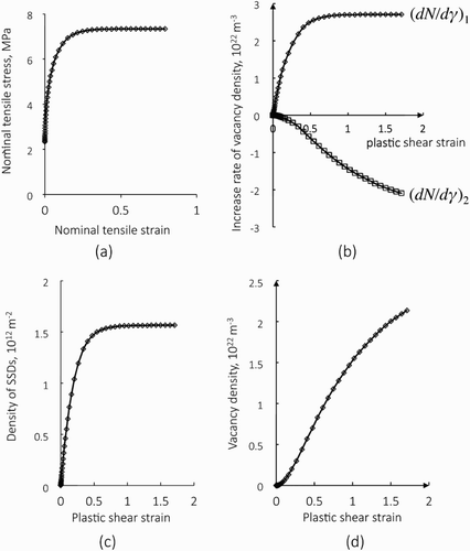
As shown in (b), the rate of vacancy generation (dN/dγ)1 increases rapidly at the initial stage of deformation, which is due to the quick increase of the SSD density and their annihilation, and after the saturation of SSD density, the generation rate of vacancy reaches a constant. On the other hand, the decrease rate (dN/dγ)2 monotonically grows, which is due to the mechanism that vacancies are generated at an increasing or constant rate of (dN/dγ)1 and the growing density of vacancies experience more chance to be swept out by moving dislocations. As a result of these increment and decrement, the total density of vacancies increases as shown in (d), where the net increase rate begins to be lowered approximately after the plastic shear strain is 0.5. When the plastic shear strain is 1.5, the total density of vacancies is approximately 2 × 10²² m−3, while its concentration (ratio to the atomic density) is smaller than 1 ppm.
5.2. Effect of forest dislocations, microstructure length scale, dislocation annihilation distance and dislocation sweep range on the vacancy evolution
(a,b) compares nominal strain vs. strain curves and evolutions of vacancy density for models 9c00 with c* = 100 and 9c01 with c* = 15, respectively. The magnitude of c* plays a noticeable role both in the stress–strain relation and in the evolution of the atomic vacancy density.
Figure 4. Comparisons of nominal stress vs. strain curves (a), and evolutions of vacancy density (b) for models 9c01 (c* = 15) and 9c00 (c* = 100), respectively. Magnitude of the coefficient c* plays a notable role both in the stress–strain relation and in the evolution of the atomic vacancy density.
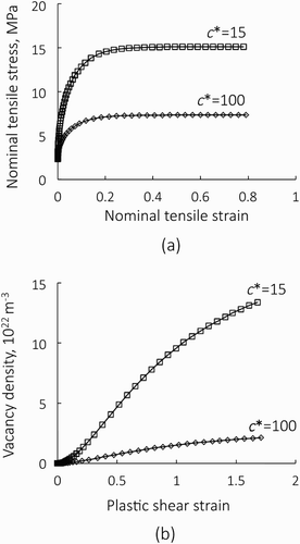
As shown in , the materials length scale of these models is sufficiently large (d = d* = 1000 μm) and the effective spacing of forest dislocations is smaller than this. Therefore, the mean free path of dislocations is given by the effective spacing of forest dislocations. Slip deformation of these models, on the other hand, takes place only on the primary slip system and the density of forest dislocations is kept constant. Accordingly, the mean free path of dislocations is kept constant and this value scales with c*.
Smaller c* induces a quicker increase of SSD densities and its saturation value is also higher, since the saturation density is inversely proportional to the mean free path as shown in Equation (13). By this mechanism, the first term of the increment of the atomic vacancy density scales with 1/c*.
When the density of SSDs saturate, the first term in the right-hand side of Equation (6) is kept at a large value and atomic vacancies are produced constantly. Eventually, as the vacancy density grows, the effect of dislocation sweep will become noticeable and this will bring a non-linearity to the density evolution; however, it is interesting to note that the vacancy density scales approximately with 1/c* in (b).
compares the result obtained for the model 9c02 with 9c00. The curve with label H.T. for the model 9c02 was obtained with D = 25 and yp = 5
, assuming that pair annihilation and vacancy sweep take place in larger extent in some circumstances such as that the deformation temperature is higher.
Figure 5. Effects of the annihilation distance D and sweep range yp on the evolution of the vacancy density. The result with label R.T. for the model 9c00 was obtained with D = 5b and yp = b, while the result with label H.T. for the model 9c02 was obtained with D = 25b and yp = 5b.
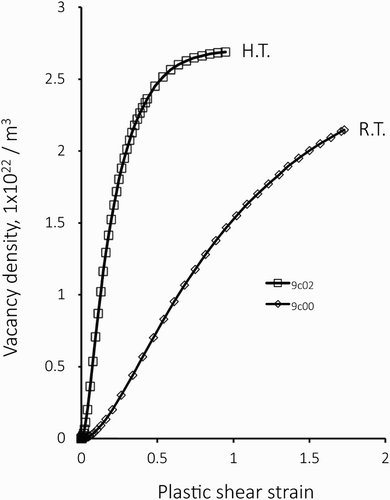
Larger values for D and yp result in a quicker accumulation of atomic vacancies and the density in the model 9c02 appears to reach its saturation level when the plastic shear strain is at about 1. Let us examine the saturation density of vacancies. Assuming dN(n) = 0 in Equation (6) when the vacancy density saturates, we obtain [Citation22],(14) where
denotes the saturation densities of vacancy.
is the edge component of saturated SSD density, which is obtained from Equations (8) and (13) as follows:
(15) The saturation density is from Equations (14) and (15),
(16)
Substitution of each value for quantities on the right-hand side of Equation (16) gives the saturation density of 2.71 × 2022 m−3, which is in good agreement with the result shown in . Vacancy density in the model 9c00 is observed to approach the same value of saturation slowly.
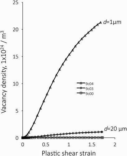
compares the density evolutions in models with different material length scales. Smaller length scale causes a larger vacancy density. In the model 9c04 with d = 1 μm, the vacancy density is larger than 1.5 × 2025 m−3 when the plastic shear strain is 1. The rapid growth of the vacancy density in models with smaller materials length scale is induced by a shorter dislocation mean free path, the rapid increase of SSD density and intense emission of vacancies.
Figure 6. Comparison of the density evolutions in models with different material length scale d. These models deform by single slip and D = 5b and yp = b are used. Smaller d results in a larger vacancy density.
(a) shows nominal stress vs. strain curves for models 9c05 where single-slip deformation takes place and D = 25 and yp = 5
. The material length scale is d* = d = 1 μm. Plastic slip starts when the nominal stress is approximately 126 MPa as shown by the arrow in (a) and after a very high strain hardening, which is a result of sharp increase in the density of SSDs, plastic flow stress levels off at approximately 200 MPa. Results obtained for 9c00 and 9c02 are also shown for comparison. The difference of the yield stress for these models comes from the third term in the right-hand side of Equation (9) [Citation27]. The solid curve in (b) shows true stress vs. true strain relation of the model 9c05 and the broken line shows the tangent modulus calculated from the true stress–strain relation.Footnote2 Consideré condition for a stable deformation is given as follows:
(17) where σtrue and εtrue denote true stress and true strain, respectively. The arrow in (b) indicates the point where the tangent modulus is equal to the true stress. If the specimen includes inhomogeneity, the deformation after the Consideré condition will be unstable. In the present analysis, the deformation continues because no inhomogeneity is introduced. (c) shows the evolution of vacancy density. The point when the Consideré condition is lost is also shown in (c). It is noted that the maximum vacancy density, which is approximately 2.71 × 1025, is about two times larger than the value when the deformation becomes inherently unstable. If we divide the maximum vacancy density by the atomic density, the concentration of vacancy is 0.32 × 10⁻³.
Figure 7. Response of the model 9c05 in which deformation is conducted by single slip and D = 25b and yp = 5b are used. Nominal stress vs. strain curves for the models 9c05, 9c00 and 9c02 (a), True stress vs. strain curve of 9c05 and its tangent moduls (b) and evolution of atomic vacancy (c), respectively.
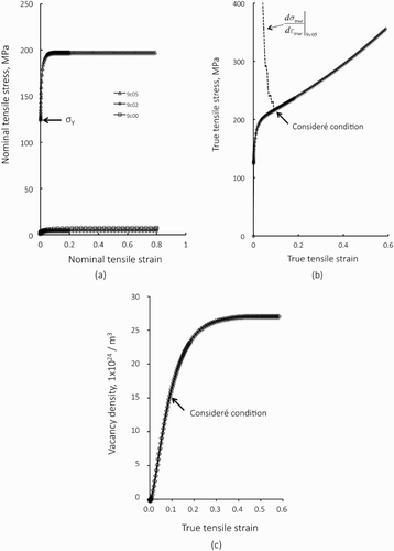
Materials, in general, will include inhomogeneity and imperfections and the deformation should be instable after the Consideré condition is lost and strain hardening is no more sufficient to accommodate strain localisation [Citation36]. In such a region where localised slip takes place, stress state will turn to be triaxial and slip on multiple systems could start. Under such circumstance, the evolution of the vacancy density could be more aggressive than the results shown in (c).
5.3. Vacancy evolution during double-slip deformation
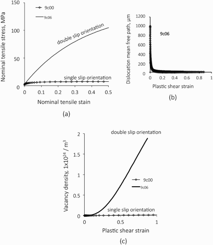
shows comparisons of the results obtained for models with single-slip (9c00) and double-slip (9c06) orientations. When the deformation is conducted by single slip, the stress–strain curve shows a ordinary parabolic curve as shown in (a),Footnote3 while in the model with double-slip orientation, the deformation curve is initially straight with a higher strain hardening rate, showing stage II character for the deformation curves of single crystals, and the hardening rate gradually decreases due to dislocation annihilation. The dislocation mean free path for the model of 9c00 is a constant and 1000 μm throughout the deformation, while the mean free path in the model 9c06 decreases rapidly with the deformation as shown in (b). This decrease results in a quicker accumulation of dislocations and at the same time, a significant increase of the vacancy density takes place as shown in (c).
Figure 8. Comparison of the results for models with single-slip (9c00) and double-slip (9c06) orientation. Nominal tensile stress vs. strain curves (a), dislocation mean free path for the model of double-slip orientation and the evolution of atomic vacancies (c), respectively.
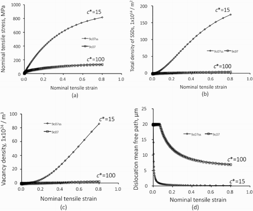
(a–d) shows results obtained for models of 9c07 and 9c07ss where double-slip deformations take place but with different values for c*. Since the deformation takes on two slip systems, nominal tensile strain is used for the measure of deformation and for the horizontal axis of . (a) shows nominal stress–strain curves. The flow stress level is noticeably high in the model 9c07ss where the dislocation mean free path is smaller compared to the model 9c07 and the flow stresses for 9c07ss is approximately 6.1 times larger than that for 9c07. This magnification is close to the ratio of c* values for the models of 9c07ss and 9c07. (b,c) shows total density of SSDs and vacancy densities plotted as against the nominal tensile stain, respectively. Similar to the results shown in but more aggressively, magnitude of the coefficient c* plays a significant role in these microscopic aspects; ratios for the SSD densities for models 9c07ss and 9c07 when the nominal tensile strain is 0.8 is approximately 44 and this is close to the square of the ratio of c* for these models, which is about 44.5. Similarly, ratio of the vacancy density in 9c07ss and 9c07 when the nominal tensile strain is 0.8 is approximately 39. Mean free path curves for the two models are shown in (d). The dislocation mean free path for the model 9c07 is initially controlled by the materials length scale, which is 20 μm, and then shortened by the effective spacing of accumulated dislocations. In contrast to this, density of forest dislocations determines the mean free path in the model 9c07ss from the onset of slip deformation and decrease rapidly as shown in (d). This brings about a large difference in the accumulated densities of SSDs and atomic vacancies.
5.4. Effect of dislocation sweep range
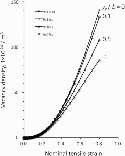
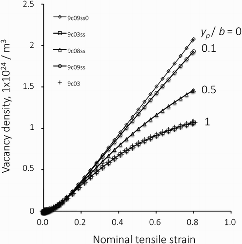
compares evolution of vacancy densities in single-slip models with various values for the dislocation sweep range yp. The microstructure length scale is 20 μm. Shorter dislocation sweep range of yp results in the larger value of the vacancy density and the increase rate of the vacancy density is lowered with deformation especially when = 0.5 and 1. Nevertheless, variation of the vacancy densities with yp values remains rather small. The maximum values obtained in these analyses when the nominal tensile strain is 0.8 are at the order of 1 × 1024 m−3. In these analysis, c* = 15 was used except for the model 9c03 with c* = 100 showing that c* did not take any effect when the slip took place on single system.
Figure 10. Evolution of the vacancy density in models with single-slip orientation and the materials length scale d = 20 μm. Shorter dislocation sweep range of yp results in the larger value of the vacancy density; however, the the maximum values obtained in these analyses remain at the order of 1 × 1024 m−3. c* = 15 was used except for the model 9c03 with c* = 100 showing that c* did not take any effect when the slip took place on single system.
shows the evolution of the vacancy density in models with double-slip orientation and under some conditions for yp. The microstructure length scales are d = d* = 20 μm. Similar to the results obtained for the case of single-slip deformation, shorter dislocation sweep range of yp results in larger values of the vacancy density. The maximum values obtained in these analyses reached the order of 1 × 1026 m−3, which were about 100 times larger than those obtained for the single-slip deformation cases. If we divide these maximum densities by the atomic density, which is approximately 8.5 × 1028 m−3, the vacancy concentration reaches the order of 0.1%.
5.5. Some possibilities for the effect of vacancy absorption into dislocation lines and cross-slip of screw dislocations
Edge dislocations will climb after sweeping of sufficient number of vacancies and through this process, pair annihilation of edge dislocations could be possible in a wider extent. Therefore, the annihilation distance of D can be a function of the rate of dislocation sweeping, which is given by the second term in the parenthesis in the right-hand side of Equation (6). This will accelerate the pair annihilation and modify the result; however, details are left for further study. It is anticipated that, before the full absorption of vacancies and climb of the dislocation line, absorption of vacancies by dislocations will result in the formation of jogs and this will decrease the mobility of dislocation lines. Mobility of dislocations is included in the lattice friction term in Equation (9) and it seems reasonable to introduce the effect of vacancy density in such a manner that . Decrease of the mobility will also have influence on the mean free path of dislocations and this could be modelled by modification of Equation (5), such as making the parameter c* as a function of the vacancy density or add a new term for the vacancy density.
Cross-slip and pair annihilation of screw dislocations do not contribute to the generation of atomic vacancy but will contribute to the stress–strain relations since the relation is determined by the evolution of dislocation densities. Evolution law for the dislocation density evaluated by the model of Kocks and Mecking does not discriminate edge and screw components and this is another point of discussion for further study.
6. Summary
By using a theoretical model by Essmann and Mughrabi [Citation22] for the increment of atomic vacancy as well as some models for the movement and accumulation of the SSDs, density evolution of atomic vacancies due to pair annihilation of edge dislocations was obtained for a variety of models. Results are summarised as follows:
Density of accumulated vacancy varied significantly with the materials length scale of the microstructure and multiplication of slip activities. When the length scale was sufficiently large and the slip took on a single system, the vacancy density only reached the order of 1022–1023 m−3 even after the deformation of plastic shear strain of 1. While in models with the length scale of 1 μm, the vacancy density reached the order of 1025 m−3.
Under the double-slip condition, the vacancy density was at the order of 1024–1025 m−3 in models with a sufficiently large length scale after deformation of plastic shear strain of 1. In models with the microstructural length scale d = d* = 20 μm, the vacancy density after tensile deformation of 0.8 strain reached 1026 m−3.
Magnitudes of dislocation annihilation distance and dislocation sweep range were shown to have relatively minor effects to the evolution of vacancy density. Larger values for the dislocation annihilation distance and sweep range resulted in a more rapid accumulation of the vacancy density; however, the saturation density of the vacancy was at the same order of magnitude to the one obtained for the model with smaller values of dislocation annihilation distance and dislocation sweep range.
Effect of forest dislocations, which was introduced to the model by the parameter c* in Equation (5), to the density evolution of vacancies was also significant. Under single- and double-slip conditions, the accumulated density of vacancies varied approximately in proportion to 1/c* and 1/(c*)2, respectively.
Disclosure statement
No potential conflict of interest was reported by the author.
ORCID
Tetsuya Ohashi http://orcid.org/0000-0002-7195-8924
Additional information
Funding
Notes
1 Movement and annihilation of dislocations will result in the generation of vacancies and, vacancies absorbed by dislocations will modify the movement of dislocations in turn. Some possibilities for the effect of vacancy absorption into dislocations will be discussed in Section 5.5.
2 True stress σtrue and true strain εtrue were obtained from the nominal values by the following relation,
Tangent modulus was calculated from the true stress and true strain using second-order accurate central difference scheme.
3 Transition from deformation stages I to II will not take place in the analysis of the models with single slip orientation because the models do not include any inhomogeneity.
References
- J.-I. Takamura, I. Takahashi, and M. Amano, Lattice defects in deformed low-carbon steels and the annealing stage, Trans. Iron Steel Inst. Jpn. 9 (1969), pp. 216–221.
- H. Kimura and R. Maddin, Concentration of vacancies in gold single crystals deformed at high temperatures, Acta Metall. 12 (1964), pp. 1065–1069. doi: 10.1016/0001-6160(64)90078-1
- D.R. Trinkle, Automatic numerical evaluation of vacancy-mediated transport for arbitrary crystals: Onsager coefficients in the dilute limit using a green function approach, Philos. Mag. 97 (2017), pp. 2514–2563. doi: 10.1080/14786435.2017.1340685
- E. Ozawa and H. Kimura, Excess vacancies and the nucleation of precipitates in aluminum-silicon alloys, Acta Metall. 18 (1970), pp. 995–1004. doi: 10.1016/0001-6160(70)90055-6
- M. Feller-Kniepmeier and J. Gobrecht, Influence of excess vacancies on recrystallization of high purity gold, Acta Metall. 19 (1971), pp. 569–576. doi: 10.1016/0001-6160(71)90009-5
- Y. Estrin and K. Lücke, Theory of vacancy-controlled grain boundary motion, Acta Metall. 30 (1982), pp. 983–998. doi: 10.1016/0001-6160(82)90206-1
- S.L. Semiatin, M.W. Corbett, P.N. Fagin, G.A. Salishchev, and C.S. Lee, Dynamic-coarsening behavior of an α/β titanium alloy, Metall. Mater. Trans. A. 37 (2006), pp. 1125–1136. doi: 10.1007/s11661-006-1091-x
- F.R.N. Nabarro, Kinetics of Mughrabi’s model of internal stresses, Acta Metall. Mater. 38 (1990), pp. 637–641. doi: 10.1016/0956-7151(90)90219-7
- A.M. Cuitiño and M. Ortiz, Ductile fracture by vacancy condensation in F.C.C. single crystals, Acta Mater. 44 (1996), pp. 427–436. doi: 10.1016/1359-6454(95)00220-0
- S.H. Goods and L.M. Brown, Overview No. 1. The nucleation of cavities by plastic deformation, Acta Metall. 27 (1979), pp. 1–15. doi: 10.1016/0001-6160(79)90051-8
- V.A. Lubarda, M.S. Schneider, D.H. Kalantar, B.A. Remington, and M.A. Meyers, Void growth by dislocation emission, Acta Mater. 52 (2004), pp. 1397–1408. doi: 10.1016/j.actamat.2003.11.022
- L.M. Hsiung and N.S. Stoloff, A point defect model for fatigue crack initiation in Ni3Al + B single crystals, Acta Metall. Mater. 38 (1990), pp. 1191–1200. doi: 10.1016/0956-7151(90)90192-J
- J. Man, K. Obrtlík, and J. Polák, Extrusions and intrusions in fatigued metals. Part 1. State of the art and history, Philos. Mag. 89 (2009), pp. 1295–1336. doi: 10.1080/14786430902917616
- J. Man, P. Klapetek, O. Man, A. Weidner, K. Obrtlík, and J. Polák, Extrusions and intrusions in fatigued metals. Part 2. AFM and EBSD study of the early growth of extrusions and intrusions in 316L steel fatigued at room temperature, Philos. Mag. 89 (2009), pp. 1337–1372. doi: 10.1080/14786430902917624
- F.P.E. Dunne, Fatigue crack nucleation: mechanistic modelling across the length scales, Curr. Opin. Solid State Mater. Sci. 18 (2014), pp. 170–179. doi: 10.1016/j.cossms.2014.02.005
- S.D. Antolovich and R.W. Armstrong, Plastic strain localization in metals: origins and consequences, Prog. Mater. Sci. 59 (2014), pp. 1–160. doi: 10.1016/j.pmatsci.2013.06.001
- I.S. Yasnikov, A. Vinogradov, and Y. Estrin, Revisiting the Considere criterion from the viewpoint of dislocation theory fundamentals, Scr. Mater. 76 (2014), pp. 37–40. doi: 10.1016/j.scriptamat.2013.12.009
- A. Vinogradov, I.S. Yasnikov, H. Matsuyama, M. Uchida, Y. Kaneko, and Y. Estrin, Controlling strength and ductility: dislocation-based model of necking instability and its verification for ultrafine grain 316L steel, Acta Mater. 106 (2016), pp. 295–303. doi: 10.1016/j.actamat.2016.01.005
- M. Nagumo, T. Yagi, and H. Saitoh, Deformation-induced defects controlling fracture toughness of steel revealed by tritium desorption behaviors, Acta Mater. 48 (2000), pp. 943–951. doi: 10.1016/S1359-6454(99)00392-4
- K. Sakaki, T. Kawase, M. Hirato, M. Mizuno, H. Araki, Y. Shirai, and M. Nagumo, The effect of hydrogen on vacancy generation in iron by plastic deformation, Scr. Mater. 55 (2006), pp. 1031–1034. doi: 10.1016/j.scriptamat.2006.08.030
- S. Li, Y. Li, Y. C. Lo, T. Neeraj, R. Srinivasan, X. Ding, J. Sun, L. Qi, P. Gumbsch and J. Li, The interaction of dislocations and hydrogen-vacancy complexes and its importance for deformation-induced proto nano-voids formation in α-Fe, Int. J. Plast. 74 (2015), pp. 175–191. doi: 10.1016/j.ijplas.2015.05.017
- U. Essmann and H. Mughrabi, Annihilation of dislocations during tensile and cyclic deformation and limits of dislocation densities, Philos. Mag. A 40 (1979), pp. 731–756. doi: 10.1080/01418617908234871
- T. Ohashi, Computer simulation of non-uniform multiple slip in face centered cubic bicrystals, Trans. JIM 28 (1987), pp. 906–915. doi: 10.2320/matertrans1960.28.906
- U.F. Kocks and H. Mecking, Physics and phenomenology of strain hardening: the FCC case, Prog. Mater. Sci. 48 (2003), pp. 171–273. doi: 10.1016/S0079-6425(02)00003-8
- U.F. Kocks, Laws for work-hardening and low-temperature creep, Trans. ASME, J. Eng. Mat. Tech. 98 (1976), pp. 76–85. doi: 10.1115/1.3443340
- H. Mecking and U.F. Kocks, Kinetics of flow and strain-hardening, Acta Metall. 29 (1981), pp. 1865–1875. doi: 10.1016/0001-6160(81)90112-7
- T. Ohashi, M. Kawamukai, and H. Zbib, A multiscale approach for modeling scale-dependent yield stress in polycrystalline metals, Int. J. Plast. 23 (2007), pp. 897–914. doi: 10.1016/j.ijplas.2006.10.002
- T. Ohashi and Y. Okuyama, Crystal plasticity analysis of mechanical response and size effect in two phase alloys with dispersion of fine particles, Key Eng. Mater. 725 (2017), pp. 267–272. doi: 10.4028/www.scientific.net/KEM.725.267
- T. Ohashi, Finite-element analysis of plastic slip and evolution of geometrically necessary dislocations in fcc crystals. Philos. Mag. Lett. 75 (1997), pp. 51–57. doi: 10.1080/095008397179741
- T. Ohashi, Three-demensional structures of the geometrically necessary dislocations generated from non-uniformities in metal microstructures, in IUTAM Symposium on Multiscale Modeling and Characterization of Elastic-Inelastic Behavior of Engineering Materials, S. Ahzi, M. Cherkaoui, M.A. Khaleel, H.M. Zbib, M.A. Zikry, and B. Lamatina, eds., Kluwer Academic Publishers, Dordrecht, 2002, pp. 183–190.
- T. Ohashi, A New model of scale dependent crystal plasticity analysis, in IUTAM Symposium on Mesoscopic Dynamics of Fracture Process and Materials Strength, H. Kitagawa and Y. Shibutani, eds., Kluwer Academic Publishers, Dordrecht, 2003, pp. 97–106.
- T. Ohashi, Three dimensional structures of the geometrically necessary dislocations in matrix-inclusion systems under uniaxial tensile loading, Int. J. Plast. 20 (2004), pp. 1093–1109. doi: 10.1016/j.ijplas.2003.10.005
- T. Ohashi, Crystal plasticity analysis of dislocation emission from micro voids, Int. J. Plast. 21 (2005), pp. 2071–2088. doi: 10.1016/j.ijplas.2005.03.018
- D. Kuhlmann-Wilsdorf, Theory of plastic deformation: - properties of low energy dislocation structures, Mater. Sci. Eng. A 113 (1989), pp. 1–41. doi: 10.1016/0921-5093(89)90290-6
- T. Ohashi, M. Kawamukai, and H. Zbib, Crystal plasticity modeling of scale dependency of yield stress for metal polycrystals, International Symposium on Plasticity 2006, Halifax, 2006.
- I.S. Yasnikov, Y. Estrin, and A. Vinogradov, What governs ductility of ultrafine-grained metals? A microstructure based approach to necking instability, Acta Mater. 141 (2017), pp. 18–28. doi: 10.1016/j.actamat.2017.08.069

