
 ?Mathematical formulae have been encoded as MathML and are displayed in this HTML version using MathJax in order to improve their display. Uncheck the box to turn MathJax off. This feature requires Javascript. Click on a formula to zoom.
ABSTRACT
The theory of mechanical twinning is revisited for the case of face-centred tetragonal lattices. The motivation is an imprecision in the determination of twinning shear vector magnitude, which occurs repeatedly in the literature. The magnitude of this vector describing the mutual shear of two adjacent crystallographic planes in the process of twin formation is a function of the tetragonality of the lattice c/a. Therefore, we introduce the c/a-dependent factor f which has to be applied to the magnitude of shearing vector instead of the commonly use factor 1/6, which is correct only for perfect cubic lattices. The theory is verified by ab initio calculations of the generalised planar fault energy curves for three tetragonal materials: the nonmodulated martensite phase of Ni2FeGa magnetic shape memory alloy, γ-TiAl intermetallic and pure In. Moreover, the calculations show that the additional modification of shear vector is caused by structural optimisation due to short-range interactions in the vicinity of twin interface, especially for lattices with large deviation of c/a from 1. Such modification cannot be simply predicted from the lattice geometry.
1. Introduction
Two crystals are in a position of twins if they have (i) the same lattice, (ii) common crystallographic (twinning) plane and (iii) there is an operation of symmetry by which one crystal can be transformed into the other. This operation of symmetry can be either reflection (Type I twins) or rotation about an axis lying in the twinning plane (Type II twins). Compound twins fulfil both criteria (e.g. twins in cubic crystals). Twins can be formed either at high temperature when atoms can diffuse easily (growth twins) or at low homologous temperature as a result of stresses in the crystal (mechanical or deformation twins). The terms ‘mechanical’ twinning and ‘deformation’ twinning are synonyms that both appear in the literature frequently [Citation1]. Mechanical twinning is a common mode of plastic deformation of crystals. The experimental observations indicate that mechanical twinning can occur in many (maybe all) types of crystal lattices at suitable conditions [Citation2]. There is also wide agreement in the literature that mechanical twinning is a stress-mediated (not deformation-mediated) mechanism [Citation1]. Therefore, the term mechanical twinning is used in this paper. Mechanical twinning thus occurs when local shear stress, i.e. twinning stress, is large enough for a twin to nucleate and propagate. It means that the twinning is frequently observed in deformation under high stress, i.e. at low homologous temperatures, high strain rates or in situations where dislocation slip is difficult or the number of slip systems is limited. The notoriously cited examples of such materials are hcp crystals [Citation3–7]. Mechanical twinning has been reported also for fcc metals and related alloys, which exhibit low stacking fault energy (SFE) [Citation2, Citation8–12]. Twinning also plays a crucial role in excellent mechanical behaviour of austenitic steels [Citation13, Citation14] and medium or high entropy alloys [Citation15–18]. The same twinning modes as in fcc-like structures are active in materials exhibiting tetragonally distorted fcc-like structures [Citation19–23].
An example of a material with tetragonal lattice which will be discussed further in the paper is a γ-TiAl phase. It is a chemically ordered intermetallic with L10 structure where ordinary dislocations with two Burgers vectors are available: ½ [] and ½ [
]. Plastic deformation with non-zero c component can be achieved by activation of ‘hard’ deformation modes; either slip of superdislocations or mechanical twinning in
twin system. Detailed studies of mechanical twinning in γ-TiAl are available [Citation24–26]. The γ-TiAl phase is slightly tetragonal, the ratio c/a equals 1.016. Industrial γ-TiAl alloy are alloyed with Nb, Cr and/or other elements [Citation27] and the c/a ration can slightly vary depending on the chemical composition; however, the difference between the length of c and a parameters is only a few percent. Therefore, mechanical twinning in γ-TiAl is often in the literature described by the same elements as in fcc crystals.
A monoatomic analog of L10 structure discussed also in this work is the face-centre tetragonal structure (fct) structure, which can be found for indium, the softest metals stable in air. It crystallises in fct lattice with larger tetragonality than γ-TiAl, the c/a ratio equals 1.078 [Citation28]. Mechanical twins have been reported in In by Carpenter and Tamura [Citation29] considering the {111} plane as a twinning plane. Later, Becker et al. claimed that the twinning plane is not the {111} plane, but corresponds to ,
,
or
planes [Citation28] which was also confirmed by electron diffraction patterns [Citation30].
Mechanical twinning in fct-like systems is important also for martensitic phases of certain Heusler alloys exhibiting a shape memory effect [Citation20, Citation31–38]. The sufficiently low twinning stress (<50 MPa) observed in these materials allows high mobility of twin boundaries and it consequently results in reversible macroscopic deformation of martensite, which can be controlled even by moderate magnetic field [Citation39]. The simplest case of martensitic phase, so-called nonmodulated, exhibits tetragonally distorted L21 structure [Citation40–42], which can be described also as L10 structure with two fct-like unit cell with c/a < 1. An example of such martensite further discussed in the paper is the nonmodulated martensite of Ni2FeGa which structure consists of fct-like unit cells with c/a = 0.86 [Citation43]. The nonmodulated martensite is the result of stress-induced inter-martensitic transformation from 10M/14M modulated monoclinic martensite [Citation43,Citation44] or direct stress-induced martensitic transformation from cubic austenite at elevated temperatures [Citation45–47]. The L10 structure is also stable in Ni2FeGa alloys doped by Co [Citation48].
The twinning stress is one of the most important parameters related to mechanical twinning which can be predicted also from theoretical simulations based on the extended Peierls–Nabarro (PN) model [Citation36, Citation49–51]. The twin-boundary energy and SFE are fundamental inputs for the PN model which are usually obtained from ab initio calculations of generalised-planar-fault-energy (GPFE) curves. The GPFE curves describe the energy pathways associated with twinning [Citation10, Citation52–54] as a function magnitude of the shearing vector. The maxima on the GPFE curves correspond to barriers which Shockley partials must overcome during twin nucleation and grow whereas minima correspond to stable configurations of stacking faults consisting of different number of layers. The GPFE curves then characterise the continuous development from the perfect crystal through the intrinsic stacking fault (ISF, i.e. one-layer twin) to a multilayer twin.
One purpose of the paper is to demonstrate the differences in the magnitude of twinning shear vector between fcc and fct lattices, which are often overlooked due to the similar twinning mechanism, especially, if the tetragonality of the fct structure is small. The differences in the magnitude of
cannot be neglected, because the wrong value can lead even to inaccurate predictions of SFE or twin-boundary energy for structures with large tetragonality. Moreover, our theoretical findings are supported by ab initio calculations of GPFE for selected materials with tetragonal lattices, which demonstrate the effect of tetragonal distortion as well as the effects of structural optimisation which results in additional modification of the magnitude of
.
1.1. Crystallographic description of twinning
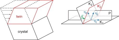
In the classical description of twinning developed by Cahn [Citation55] and Bilby and Crocker [Citation56], the twin is formed from the initial crystal by shearing. Four parameters (elements) of twinning, K1, K2, η1 and η2 are used (see ):
K1, the twinning plane, common crystallographic plane for both crystal and twin
K2, the plane which is rotated during twinning but stays undistorted. Its notation after twinning is K2’
η1, the crystallographic direction (not vector) which lies in K1 and is the direction of shearing which can transform K2 into K2’. It is also called twinning direction
η2, the crystallographic direction in plane K2 which changes in η2’ after twining; both η2 and η2’ lie in the plane of shearing S.
Figure 1. Formation of mechanical twin by shear and definition of elements of twinning.
Moreover, other parameters are used in the literature:
P, the plane of shear which contains η1, intersects K2 in direction η2; and K2’ in direction η2
, vector of shearing between two adjacent K1 crystallographic planes during the twin formation,
f, factor of vector of shearing
sd, amount of shear or shear deformation,
1.2. Twinning in fcc
The twinning in fcc will be briefly reminded in this section because it shows many similarities with twinning in face-centred tetragonal (fct) lattice.
Of course, there is more than one possibility of twinning in a chosen lattice. For example, in the case of Cu nanocrystals, twinning with K1 = {112} was reported [Citation57]. However, in materials having fcc lattice the vast majority of observed mechanical twins have the following elements:
K1 = {111}, K2 = {11}, η1 =
, η2 =
, P = {1
0},
, f = 1/6,
, Σ3 [Citation58].
The schematics of such twinning is shown in . In the right part of the schematics, faint red atoms were shifted by shearing the positions of full red atoms.
Figure 2. Crystallography of the most common twinning in fcc, schematised in (110) plane.
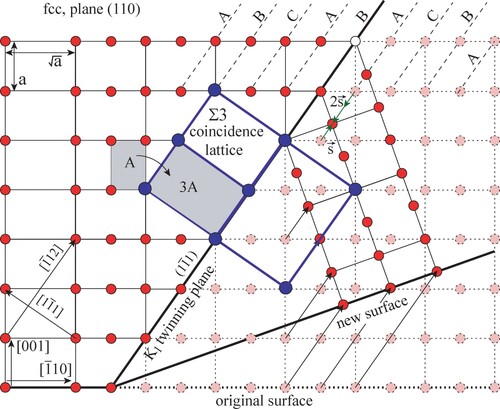
It is visible that such mechanical twinning can appear if a single Shockley dislocation with = 1/6
slip on each
plane. Please note that the same positions of atoms would be reached if the shear is done in the opposite direction and double magnitude: −2
. More generally, if we define
as oriented accordingly to
direction, the twinning can be achieved by shearing of either
or
. However, the shearing along longer of these vectors will be associated with much higher energetical barrier. Therefore, in the following parts of the paper, we will consider the shorter of these two possible shear vectors. Note also that twinning changes the orientation of surface (the angle between original surface and new surface is about 19.47°). If such mechanical twinning appears in a bulk grain in polycrystal, the twin cannot be too thick; otherwise the grain boundary would be cracked.
1.3. Twinning in fct
First, let’s note that face-centred tetragonal lattice is not listed among 14 Bravais lattices. Indeed, the symmetry elements of body-centred tetragonal (bct) and face-centred tetragonal lattices are identical, so only one of the two lattices can be considered. Because bct lattice (2 lattice nodes per unit lattice) have half of the volume of the fct lattice (4 lattice nodes per unit lattice), the bct is usually chosen as the Bravais lattice.
There are examples of slightly tetragonal materials, which have lattice close to either bcc (e.g. martensite in ferritic steels) or fcc (e.g. materials in this paper). Of course, it is reasonable to use bct lattice in the former and fct lattice for the latter case.
Let’s now study mechanical twinning with the {111} twinning plane in fct lattice. The elements of twinning and mechanism of mechanical twin formation are recalled in Appendix. Due to the reduced symmetry only the four twin directions of -type are possible [Citation27]. In the literature concerning fct crystals [Citation24, Citation36, Citation59–62], in which the magnitude of c axis differs slightly from the magnitude of a axes (e.g. γ-TiAl and Ni2FeGa nonmodulated martensite) it is sometimes erroneously mentioned that the twinning happens by the same mechanisms as in fcc crystals, including shearing by
. It is not true as the magnitude of the shear vector depends on c/a and differ from
. The dependency of twining shear on c/a was already pointed out by Yoo [Citation63,Citation64] and Kauffmann–Weiss [Citation20].
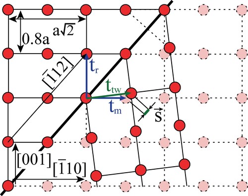
The ratio c/a in the example below () is chosen as 0.8. At first, the result of shearing along the plane by
is shown in (a). The atomic positions after such transformation are not in the mirror position accordingly to the
plane and the angle ϕ between
and
directions is not 90°. The crystal axes a and c are thus not perpendicular and such shearing is an example of phase transformation but not twinning. There is still a common coincidence lattice between the two parts of crystal.
Figure 3. (a) Result of shearing by in fct lattice, c/a = 0.8. The same positions of atoms can be reached also by shearing in the opposite direction by the vector
. (b) Result of mirroring the crystal along the
plane in fct lattice, c/a = 0.8.
![Figure 3. (a) Result of shearing by s→=1/6[1¯12] in fct lattice, c/a = 0.8. The same positions of atoms can be reached also by shearing in the opposite direction by the vector s′→. (b) Result of mirroring the crystal along the (11¯1) plane in fct lattice, c/a = 0.8.](/cms/asset/bac825c5-7022-43c9-b0ca-6758de4ba578/tphm_a_2135037_f0003_oc.jpg)
The case when the two parts of crystal show the mirror symmetry is shown in (b). The K1 is now the mirror plane and both crystals have the same lattice and lattice parameters. It is visible that the vector is shorter than
.
The fraction f of the vector of shearing can be calculated using the reflection matrix as a function of ratio r = c/a. The development is shown in Appendix and the result is
(1)
(1) The vector
is parallel to the direction
and can be also written as
(2)
(2)
Equation (1) is in an agreement with the equation for the shear deformation sd given in [Citation2]:
(3)
(3)
It is also important to note that the same position of atoms after twinning can be reached by shearing the crystal in the opposite direction, i.e. in the direction antiparallel to vector. The magnitude of the antiparallel shear vector
and the fraction f ’ (defined as value larger or equal to zero) can be calculated knowing that (see (a)):
(4)
(4)
(5)
(5)
The fractions f and f′ are plotted as a function of r in . In this figure, we plotted the absolute value of f; vector changes its orientation for r = 1/
. The particular cases are:
Figure 4. Parameters f and f ‘ as a function of ratio r = c/a. Magnitude of the vector is the unity of the y-axis.
![Figure 4. Parameters f and f ‘ as a function of ratio r = c/a. Magnitude of the [1¯12] vector is the unity of the y-axis.](/cms/asset/8b43e0b7-e19e-4684-b33b-f1d98c215b53/tphm_a_2135037_f0004_oc.jpg)
r = 1, fcc lattice, f = 1/6, f′ = 2/6
r = 1/, bcc lattice, f = 0, f′ = 1/2, (i.e. no twinning along {111} planes is possible)
r = , f = f′ = 1/4
r = , f = f′ = 1/4.
It is important to note that the direction of possible shearing is dictated by the orientation of the shear stress for a given grain. The same approach for the prediction of the magnitude of the shear vector as described in this work should be applied also to any other twin system, e.g. {101} twins or any other lattices with decreased symmetry, e.g. bct.
2. Examples of real crystals: results and discussion
To investigate the magnitude of in real crystals at the atomic level we employed ab initio calculations based on density functional theory. We calculated the GPFE curves as a function of shearing vector. The magnitude of
can be estimated from position of minima on the GPFE curve as can be seen in . In particular, we performed these calculations for tetragonal lattices of In, γ-TiAl and Ni2FeGa nonmodulated martensite as well as for cubic Al. The total energies used for estimation of GPFE were calculated with help of the Vienna Ab initio Simulation Package (VASP) [Citation65,Citation66] in which the electron–ion interaction was described by PAW potentials [Citation67,Citation68]. The electronic orbitals were expanded in terms of plane waves with a maximum kinetic energy of 400 eV for Al, 500 eV for In and Ni2FeGa and 600 eV for TiAl. We used the gradient-corrected exchange–correlation functional proposed by Perdew, Burke, and Ernzerhof [Citation69]. The Brillouin zone (BZ) was sampled using a Γ-point-centred mesh with the smallest allowed spacing between k-points in each direction of the reciprocal lattice vectors equal to 0.10 Å−1 for Al, In and Ni2FeGa and 0.08 Å−1 for TiAl. The integration over the BZ used the Methfessel-Paxton smearing method [Citation70] with a 0.02 eV smearing width. The total energy was calculated with high precision by convergence to 10−6 eV per computational cell. The ground-state structures without stacking faults were fully optimised with help of conjugate-gradient method and optimisation was terminated when all forces acting on the atoms converged to within 10−3 eV·Å−2 and all components of the stress tensor changed less than 0.1 GPa. Such settings provide lattice parameters, which are summarised in together with experimental data. The table further contains magnitudes of Burgers vector
, shearing vector
and the factor f, which were obtained from calculated lattice parameters according to equations (1) and (2), respectively.
Figure 5. The generalised planar fault energies γ (GPFE) of (a) Al, (b) In, (c) TiAl, (d) Ni2FeGa as a function of ratio (the ratio of shear displacement
and Burgers vector
. The structures in each subplot display from left to right the perfect lattice, the intrinsic stacking fault, and two- and three-layer twins. The dashed arrows correspond to the minima of non-optimised GPFE whereas solid arrows represent the minima of fully optimised GPFE. If only solid arrow is shown, both minima coincide.
![Figure 5. The generalised planar fault energies γ (GPFE) of (a) Al, (b) In, (c) TiAl, (d) Ni2FeGa as a function of |s→|/|b→| ratio (the ratio of shear displacement s→ and Burgers vector b→=1/6[1¯12]). The structures in each subplot display from left to right the perfect lattice, the intrinsic stacking fault, and two- and three-layer twins. The dashed arrows correspond to the minima of non-optimised GPFE whereas solid arrows represent the minima of fully optimised GPFE. If only solid arrow is shown, both minima coincide.](/cms/asset/c5606412-beb0-4fc6-ad6a-a17fce6036a9/tphm_a_2135037_f0005_oc.jpg)
Table 1. Experimental and ab initio lattice parameters a and c/a and magnitude of Burges vector , shearing vector
, ratio
, and factor f calculated from ab initio lattice parameters. The experimental data were taken from the following works: Al [Citation71]; In [Citation72]; TiAl [Citation73]; Ni2FeGa [Citation43].
After structural optimisation of the lattices the GPFE curves were calculated by shearing n successive layers in a supercell along the
direction in similar way as explained for example in Ref. [Citation36]. We used the supercells periodically repeated in all directions (no free surfaces) consisting from eight
lattice planes with lattice vectors corresponding to
, [
] and
directions of the fct lattice. The minimum corresponding to ISF was found by continuous translating (sliding) layers 5–8 relative to layers 1–4 about 1/14
. The exact position of the minimum was then estimated by cubic interpolation. The two-layer and three-layer twins were obtained by further translating (sliding) of layers 6–8 and 7–8, respectively, starting from the minimum estimated in the previous step as displayed in . Initially, we calculated the GPFE curve only by layers translating without any structural optimisation of atomic positions. Such configuration corresponds to the ideal twin geometry as described in and (b). Further, we fully optimised all atomic position for several configurations around minima obtained without structural optimisation to minimise the short-range interactions in the vicinity of stacking faults. The structural optimisation could result in further modification of shearing vector magnitude, which is caused by non-equilibrium geometry of ideal twin boundary or mutual interaction of adjacent twin boundaries in twins with thickness only few layers. The lattice vectors of the supercell remain constant during the optimisation.
The results for all studied materials are summarised in , where generalised planar fault energies γ (the total energies of the supercell with respect to the total energy of perfect lattice per area of plane) are plotted as functions of shear displacement
divided by Burgers vector
. The
ratio was used to see immediately the deviation from
due to tetragonality of the lattice. The
ratios of ISF and two-layer (
) and three-layer (
) twins are summarised in together with corresponding generalised planar fault energies γisf, γ2t and γ3t.
Table 2. Energies of intrinsic stacking fault γisf, two-layer twin γ2t and three-layer twin γ3t in mJ/m2 and corresponding ratio of vectors and
for non-optimised and fully-optimised structures.
Aluminium
For cubic fcc Al (c/a = 1, (a)) the minima on non-optimised GPFE curves perfectly coincides with integer numbers and therefore the factor f is equal to 1/6 as expected. The structural optimisation of atomic positions results in modest shortening of for ISF resulting in
. However, the position of minima corresponding to wider twins deviates from the integer number about the same value as for ISF (
), which indicates that the shortening of
is localised exactly at the twin boundary and the shear vector between layers inside a thicker twin has the factor f of 1/6. The structural optimisation also slightly decreases the energies of twin boundaries about 15–30 mJ/m2 compared to non-optimised structures.
Indium
The positions of minima in terms of deviate significantly from integer numbers for materials with tetragonal lattices and deviation increases with increasing thickness of twin. The largest deviations were found for In, which exhibit also the largest deviation of c/a from 1. Although the elongation of
does not reach the predicted value of
ratio 1.17 even for ISF, the
is still bigger than 1 and equals to 1.12 and magnitude of
further increases for two-layer twin in non-optimised structure (see dashed arrows on (b)). The average value of
(considering also the three-layer twin) agrees much better with predicted value as the average of
. The structural optimisation results in significant elongation of
for ISF but further disappears for wider twins (see solid arrows in (b)). The observed elongation of
can be explained by low thermodynamic stability of the
ISF, because the
plane is not the twining plane observed experimentally [Citation28]. In this work the
twins were used only to illustrate the effect of c/a in fct lattices. We calculated also the energies γ for the experimentally observed twin with
plane as the twinning plane. Such twin exhibits energies approximately 10 mJ/m2 which is significantly lower than energies obtained for
twin (compare with values in ). Therefore, the very low energies of
twins are in agreement with experimental observations and explain softness of In. However, the significant deviation of
from
is apparent also for energetically less preferred
twins.
γ-TiAl
Perfect agreement with predicted values of was found for γ-TiAl alloy, which exhibits lower c/a than In and where
twins are indeed observed experimentally [Citation74]. The non-optimised twins exhibit nearly the predicted
ratio 1.06 independently on their thickness. The optimised ISF exhibits
which is slightly lower value than expected, but this shortening does not appear for wider twins, where average
is again equal to 1.06 as can be seen in (c). Because the deviation of
from
is very small, the correct value of
has only negligible effect on predicted values of SFE and twin-boundary energy.
Ni2FeGa nonmodulated martensite
The Ni2FeGa magnetic shape memory alloy exhibit c/a ratio smaller than 1 and therefore the should exhibits values smaller than integer numbers. Because the L10 unit cell of Ni2FeGa is formed by two fct-like unit cell (
), the c/a ratio and the
twinning plane is considered with respect to this fct-like lattice as is explained in Ref. [Citation47]. The non-optimised GPFE curve on (d) exhibits minimum for ISF at
equal to 0.87 which corresponds very well to the predicted value. The magnitude of
even further decreases for wider twins, because values of
and
are smaller than predicted values 1.74 and 2.61, respectively. The structural optimisation results in the increased magnitude of
. However, the magnitude of
of optimised twins never reach the integer numbers (compare dashed and solid arrows in (d)). There is also a large difference between energies of optimised and non-optimised twins, which could be caused by disadvantageous geometry of ideal twin boundary. Although the energy of thicker twins should converge to a constant value which is further independent on the twin thickness as can be seen for Al, In and TiAl, the energy of three-layer twin in Ni2FeGa is about 25% bigger then energies of ISF and two-layer twin. It indicates a strong mutual interaction of twin boundaries for twins with small thickness. Similar effects have been reported by Gruner et al. [Citation75] for twins in analogue material of Ni2FeGa – the nonmodulated martensite of Ni2MnGa magnetic shape memory alloy. In this material the interaction of adjacent twin boundaries results in even higher stability of two-layer twin than detwinned structure [Citation76].
3. Conclusion
We performed a detailed theoretical study of twin system in fct lattice with the aim to estimate the magnitude of twinning shear vector
. Although the twinning in fct crystals is realised by similar mechanisms as in fcc crystals, we demonstrate that the magnitude of
is not equal to
as is repeatedly claimed in the literature but a c/a-dependent factor f has to be used instead of 1/6 ratio. The shearing about
in fct will not result in mirror symmetry of newly created twin accordingly to the
plane but to the change of the lattice type, i.e. in the phase transformation. To obtain the perfect mirror symmetry of atomic positions after twining the shearing of
= f
is necessary (f = 1/6 if c/a = 1). These theoretical findings are further supported by ab initio calculations of generalised planar fault energies (GPFE) for In, TiAl and Ni2FeGa exhibiting fct-like structures as well as for fcc cubic Al. Without the structural optimisation the minima on the GPFE curves corresponds very well to the predicted values of
= f
. However, the structural optimisation of atomic positions results in further modification of
due to minimisation of the short-range interactions at the twin-boundary plane. Such modification of
cannot be simply predicted from lattice geometry but require ab initio simulations. The described effects are relatively small in materials with small tetragonality like γ-TiAl but cannot be neglected if c axis differs from a axes significantly like in Ni2FeGa.
Acknowledgements
The theoretical calculations were performed at the IT4I facilities, which are supported through the project e-INFRA CZ [ID:90140]. Authors thanks to Jan Fikar for fruitful discussions.
Data availability
Data will be made available on request.
Disclosure statement
No potential conflict of interest was reported by the author(s).
Correction Statement
This article has been corrected with minor changes. These changes do not impact the academic content of the article.
Additional information
Funding
References
- P.M. Anderson, J.P. Hirth and J. Lothe, Theory of Dislocations, 3rd ed, Cambridge University Press, Cambridge, England, 2017.
- J.W. Christian and S. Mahajan, Deformation twinning. Prog. Mater. Sci. 39 (1995), pp. 1–157. doi:10.1016/0079-6425(94)00007-7.
- J. Wang, J.P. Hirth and C.N. Tomé, (1¯012) Twinning nucleation mechanisms in hexagonal-close-packed crystals. Acta Mater. 57 (2009), pp. 5521–5530. doi:10.1016/j.actamat.2009.07.047.
- H. Wang, P.D. Wu, J. Wang and C.N. Tomé, A crystal plasticity model for hexagonal close packed (HCP) crystals including twinning and de-twinning mechanisms. Int. J. Plast 49 (2013), pp. 36–52. doi:10.1016/j.ijplas.2013.02.016.
- B. Anthony, B. Leu, I.J. Beyerlein and V.M. Miller, Deformation twin interactions with grain boundary particles in multi-phase magnesium alloys. Acta Mater. 219 (2021), pp. 117225. doi:10.1016/j.actamat.2021.117225.
- J. Li, M. Sui and B. Li, A half-shear-half-shuffle mechanism and the single-layer twinning dislocation for {112¯2}〈112¯3¯〉 mode in hexagonal close-packed titanium. Acta Mater. 216 (2021), pp. 117150. doi:10.1016/j.actamat.2021.117150.
- S. Wang, K. Dang, R.J. McCabe, L. Capolungo and C.N. Tomé, Three-dimensional atomic scale characterization of {112¯2} twin boundaries in titanium. Acta Mater. 208 (2021), pp. 116707. doi:10.1016/j.actamat.2021.116707.
- P. Zhang, X.H. An, Z.J. Zhang, S.D. Wu, S.X. Li, Z.F. Zhang, R.B. Figueiredo, N. Gao and T.G. Langdon, Optimizing strength and ductility of Cu–Zn alloys through severe plastic deformation. Scr. Mater 67 (2012), pp. 871–874. doi:10.1016/j.scriptamat.2012.07.040.
- T. Cai, Z.J. Zhang, P. Zhang, J.B. Yang and Z.F. Zhang, Competition between slip and twinning in face-centered cubic metals. J. Appl. Phys 116 (2014), pp. 163512. doi:10.1063/1.4898319.
- M. Jo, Y.M. Koo, B.-J. Lee, B. Johansson, L. Vitos and S.K. Kwon, Theory for plasticity of face-centered cubic metals. Proc. Natl. Acad. Sci. U.S.A. 111 (2014), pp. 6560–6565. doi:10.1073/pnas.1400786111.
- P. Chowdhury, H. Sehitoglu, W. Abuzaid and H.J. Maier, Mechanical response of low stacking fault energy Co–Ni alloys – continuum, mesoscopic and atomic level treatments. Int. J. Plast 71 (2015), pp. 32–61. doi:10.1016/j.ijplas.2015.04.003.
- X. An, S. Ni, M. Song and X. Liao, Deformation twinning and detwinning in face-centered cubic metallic materials. Adv. Eng. Mater 22 (2020), pp. 1900479. doi:10.1002/adem.201900479.
- B.C. De Cooman, Y. Estrin and S.K. Kim, Twinning-induced plasticity (TWIP) steels. Acta Mater. 142 (2018), pp. 283–362. doi:10.1016/j.actamat.2017.06.046.
- C. Wang, W. Cai, C. Sun, X. Li, L. Qian and J. Jiang, Strain rate effects on mechanical behavior and microstructure evolution with the sequential strains of TWIP steel. Mater. Sci. Eng. A Struct. Mater 835 (2022), pp. 142673. doi:10.1016/j.msea.2022.142673.
- Y. Deng, C.C. Tasan, K.G. Pradeep, H. Springer, A. Kostka and D. Raabe, Design of a twinning-induced plasticity high entropy alloy. Acta Mater. 94 (2015), pp. 124–133. doi:10.1016/j.actamat.2015.04.014.
- Y. Ikeda, B. Grabowski and F. Körmann, Ab initio phase stabilities and mechanical properties of multicomponent alloys: A comprehensive review for high entropy alloys and compositionally complex alloys. Mater. Charact 147 (2019), pp. 464–511. doi:10.1016/j.matchar.2018.06.019.
- X. Feng, H. Yang, R. Fan, W. Zhang, F. Meng, B. Gan and Y. Lu, Heavily twinned CoCrNi medium-entropy alloy with superior strength and crack resistance. Mater. Sci. Eng. A Struct. Mater 788 (2020), pp. 139591. doi:10.1016/j.msea.2020.139591.
- S. Picak, H.C. Yilmaz and I. Karaman, Simultaneous deformation twinning and martensitic transformation in CoCrFeMnNi high entropy alloy at high temperatures. Scr. Mater. 202 (2021), pp. 113995. doi:10.1016/j.scriptamat.2021.113995.
- L.P. Lehman, Y. Xing, T.R. Bieler and E.J. Cotts, Cyclic twin nucleation in tin-based solder alloys. Acta Mater. 58 (2010), pp. 3546–3556. doi:10.1016/j.actamat.2010.01.030.
- S. Kauffmann-Weiss, A. Kauffmann, R. Niemann, J. Freudenberger, L. Schultz and S. Fähler, Twinning phenomena along and beyond the bain path. Metals. (Basel) 3 (2013), pp. 319–336. doi:10.3390/met3040319.
- Y. Jia, Y. Wu, S. Zhao, S. Zuo, K.P. Skokov, O. Gutfleisch, C. Jiang and H. Xu, L10 rare-earth-free permanent magnets: The effects of twinning versus dislocations in Mn–Al magnets. Phys. Rev. Mater 4 (2020), pp. 094402. doi:10.1103/physrevmaterials.4.094402.
- H.T. Pham, T. Duong, K.J. Weber and J. Wong-Leung, Insights into twinning formation in cubic and tetragonal multi-cation mixed-halide perovskite. ACS Materials Lett 2 (2020), pp. 415–424. doi:10.1021/acsmaterialslett.0c00083.
- C. Boukouvala, E.R. Hopper, D.M. Kelly, P.J. Knight, J.S. Biggins and E. Ringe, Beyond simple crystal systems: Identifying twinning in body-centered tetragonal nanoparticles. Cryst. Growth Des 22 (2022), pp. 653–660. doi:10.1021/acs.cgd.1c01188.
- B. Skrotzki, Crystallographic aspects of deformation twinning and consequences for plastic deformation processes in γ-TiAl. Acta Mater. 48 (2000), pp. 851–862. doi:10.1016/S1359-6454(99)00385-7.
- A. Vinogradov, M. Heczko, V. Mazánová, M. Linderov and T. Kruml, Kinetics of cyclically-induced mechanical twinning in γ-TiAl unveiled by a combination of acoustic emission, neutron diffraction and electron microscopy. Acta Mater. 212 (2021), pp. 116921. doi:10.1016/j.actamat.2021.116921.
- H. Xiang and W. Guo, Synergistic effects of twin boundary and phase boundary for enhancing ultimate strength and ductility of lamellar TiAl single crystals. Int. J. Plast 150 (2022), pp. 103197. doi:10.1016/j.ijplas.2021.103197.
- F. Appel, J.D. Heaton Paul and M. Oehring, Gamma Titanium Aluminide Alloys: Science and Technology, 1st ed., Wiley-VCH Verlag, Weinheim, Germany, 2011.
- J.H. Becker, B. Chalmers and E.C. Garrow, Mechanical twinning of indium. Acta Crystallogr. 5 (1952), pp. 853–853. doi:10.1107/S0365110X52002380.
- H.C.H. Carpenter and S. Tamura, The formation of twinned metallic crystals. Proc. R. Soc. Lond. A Math. Phys. Sci 113 (1926), pp. 161–182. doi:10.1098/rspa.1926.0144.
- G. Remaut, A. Lagasse and S. Ameltnckx, The electron microscopic observation of mechanical twins in indium. Phys. Status Solidi B Basic Res 6 (1964), pp. 723–731. doi:10.1002/pssb.19640060312.
- P. Sedlák, H. Seiner, L. Bodnárová, O. Heczko and M. Landa, Elastic constants of non-modulated Ni–Mn–Ga martensite. Scr. Mater 136 (2017), pp. 20–23. doi:10.1016/j.scriptamat.2017.03.041.
- L. Bodnárová, M. Zelený, P. Sedlák, L. Straka, O. Heczko, A. Sozinov and H. Seiner, Switching the soft shearing mode orientation in Ni–Mn–Ga non-modulated martensite by Co and Cu doping. Smart Mater. Struct 29 (2020), pp. 045022. doi:10.1088/1361-665X/ab7542.
- Y. Chumlyakov, E. Panchenko, I. Kireeva, I. Karaman, H. Sehitoglu, H.J. Maier, A. Tverdokhlebova and A. Ovsyannikov, Orientation dependence and tension/compression asymmetry of shape memory effect and superelasticity in ferromagnetic Co40Ni33Al27, Co49Ni21Ga30 and Ni54Fe19Ga27 single crystals. Mater. Sci. Eng. A Struct. Mater 481-482 (2008), pp. 95–100. doi:10.1016/j.msea.2007.02.146.
- I.V. Kireeva, Y.I. Chumlyakov, Z.V. Pobedennaya, I.V. Kretinina, E. Cesari, S.B. Kustov, C. Picornell, J. Pons and I. Karaman, Orientation dependence of superelasticity in ferromagnetic single crystals Co49Ni21Ga30. Phys. Met. Metallogr 110 (2010), pp. 78–90. doi:10.1134/S0031918X10070100.
- Y.I. Chumlyakov, I.V. Kireeva, E.Y. Panchenko, E.E. Timofeeva, Z.V. Pobedennaya, S.V. Chusov, I. Karaman, H. Maier, E. Cesari and V.A. Kirillov, High-temperature superelasticity in CoNiGa, CoNiAl, NiFeGa, and TiNi monocrystals. Russ. Phys. J 51 (2008), pp. 1016–1036. doi:10.1007/s11182-009-9143-5.
- J. Wang and H. Sehitoglu, Twinning stress in shape memory alloys: theory and experiments. Acta Mater. 61 (2013), pp. 6790–6801. doi:10.1016/j.actamat.2013.07.053.
- P. Müllner, Twinning stress of type I and type II deformation twins. Acta Mater. 176 (2019), pp. 211–219. doi:10.1016/j.actamat.2019.07.004.
- D. Shilo, E. Faran, B. Karki and P. Müllner, Twin boundary structure and mobility. Acta Mater. 220 (2021), pp. 117316. doi:10.1016/j.actamat.2021.117316.
- K. Ullakko, J.K. Huang, C. Kantner, R.C. O’Handley and V.V. Kokorin, Large magnetic-field-induced strains in Ni2MnGa single crystals. Appl. Phys. Lett 69 (1996), pp. 1966–1968. doi:10.1063/1.117637.
- J.C. Suits, Structural instability in new magnetic Heusler compounds. Solid State Commun. 18 (1976), pp. 423–425. doi:10.1016/0038-1098(76)90040-5.
- A. Ayuela, J. Enkovaara, K. Ullakko and R.M. Nieminen, Structural properties of magnetic Heusler alloys. J. Phys. Condens. Matter 11 (1999), pp. 2017–2026. doi:10.1088/0953-8984/11/8/014.
- T. Graf, C. Felser and S.S.P. Parkin, Simple rules for the understanding of Heusler compounds. Prog. Solid State Chem 39 (2011), pp. 1–50. doi:10.1016/j.progsolidstchem.2011.02.001.
- Y. Sutou, N. Kamiya, T. Omori, R. Kainuma, K. Ishida and K. Oikawa, Stress-strain characteristics in Ni–Ga–Fe ferromagnetic shape memory alloys. Appl. Phys. Lett 84 (2004), pp. 1275–1277. doi:10.1063/1.1642277.
- E.E. Timofeeva, E.Y. Panchenko, Y.I. Chumlyakov and H. Maier, Development of thermoelastic martensitic transformations in ferromagnetic [011]-oriented NiFeGa single crystals in compression. Russ. Phys. J 54 (2012), pp. 1427–1430. doi:10.1007/s11182-012-9766-9.
- F. Masdeu, J. Pons, C. Seguí, E. Cesari and J. Dutkiewicz, Some features of Ni–Fe–Ga shape memory alloys under compression. J. Magn. Magn. Mater 290-291 (2005), pp. 816–819. doi:10.1016/j.jmmm.2004.11.371.
- R.F. Hamilton, H. Sehitoglu, C. Efstathiou and H.J. Maier, Inter-martensitic transitions in Ni–Fe–Ga single crystals. Acta Mater. 55 (2007), pp. 4867–4876. doi:10.1016/j.actamat.2007.05.003.
- J. Wang, H. Sehitoglu and H.J. Maier, Dislocation slip stress prediction in shape memory alloys. Int. J. Plast 54 (2014), pp. 247–266. doi:10.1016/j.ijplas.2013.08.017.
- H. Morito, A. Fujita, K. Oikawa, K. Fukamichi, R. Kainuma, T. Kanomata and K. Ishida, Magnetic anisotropy in Ni–Fe–Ga–Co ferromagnetic shape memory alloys in the single-variant state. J. Phys. Condens. Matter 21 (2009), pp. 076001. doi:10.1088/0953-8984/21/7/076001.
- S. Kibey, J.B. Liu, D.D. Johnson and H. Sehitoglu, Predicting twinning stress in FCC metals: linking twin-energy pathways to twin nucleation. Acta Mater. 55 (2007), pp. 6843–6851. doi:10.1016/j.actamat.2007.08.042.
- H. Huang, X. Li, Z. Dong, W. Li, S. Huang, D. Meng, X. Lai, T. Liu, S. Zhu and L. Vitos, Critical stress for twinning nucleation in CrCoNi-based medium and high entropy alloys. Acta Mater. 149 (2018), pp. 388–396. doi:10.1016/j.actamat.2018.02.037.
- O.K. Celebi, A.S.K. Mohammed, J.A. Krogstad and H. Sehitoglu, Evolving dislocation cores at twin boundaries: theory of CRSS elevation. Int. J. Plast 148 (2022), pp. 103141. doi:10.1016/j.ijplas.2021.103141.
- N. Bernstein and E. Tadmor, Tight-binding calculations of stacking energies and twinnability in FCC metals. Phys. Rev. B 69 (2004), pp. 094116. doi:10.1103/PhysRevB.69.094116.
- S. Kibey, J.B. Liu, D.D. Johnson and H. Sehitoglu, Generalized planar fault energies and twinning in Cu–Al alloys. Appl. Phys. Lett 89 (2006), pp. 191911. doi:10.1063/1.2387133.
- M. Daly, A. Kumar, C.V. Singh and G. Hibbard, On the competition between nucleation and thickening in deformation twinning of face-centered cubic metals. Int. J. Plast 130 (2020), pp. 102702. doi:10.1016/j.ijplas.2020.102702.
- R.W. Cahn, Twinned crystals. Adv. Phys 3 (1954), pp. 363–445. doi:10.1080/00018735400101223.
- B.A. Bilby and A.G. Crocker, The theory of the crystallography of deformation twinning. Proc. R. Soc. Lond 288 (1965), pp. 240–255. doi:10.1098/rspa.1965.0216.
- J. Wang, O. Anderoglu, J.P. Hirth, A. Misra and X. Zhang, Dislocation structures of Σ3 {112} twin boundaries in face centered cubic metals. Appl. Phys. Lett 95 (2009), pp. 021908. doi:10.1063/1.3176979.
- M. Niewczas, Chapter 75 dislocations and twinning in face centred cubic crystals, in Dislocations in Solids, vol. 13, F.R.N. Nabarro, J.P. Hirth, eds., Elsevier, 2007. pp. 263–364.
- D. Xu, H. Wang, R. Yang and A.K. Sachdev, MD simulation of asymmetric nucleation and motion of [011] superdislocations in TiAl. Chin. Sci. Bull 59 (2014), pp. 1725–1737. doi:10.1007/s11434-014-0321-7.
- P. Dumitraschkewitz, H. Clemens, S. Mayer and D. Holec, Impact of alloying on stacking fault energies in γ-TiAl. Appl. Sci. (Basel 7 (2017), pp. 1193. doi:10.3390/app7111193.
- B. Jeong, J. Kim, T. Lee, S.-W. Kim and S. Ryu, Systematic investigation of the deformation mechanisms of a γ-TiAl single crystal. Sci. Rep 8 (2018), pp. 15200. doi:10.1038/s41598-018-33377-z.
- T. Lee, S.-W. Kim, J.Y. Kim, W.-S. Ko and S. Ryu, First-principles study of the ternary effects on the plasticity of γ-TiAl crystals. Sci. Rep 10 (2020), pp. 21614. doi:10.1038/s41598-020-77891-5.
- M.H. Yoo, Deformation twinning in superlattice structures. J. Mater. Res 4 (1989), pp. 50–54. doi:10.1557/JMR.1989.0050.
- M.H. Yoo and B.T.M. Loh, Structural and elastic properties of zonal twin dislocations in anisotropic crystals, in Fundamental Aspects of Dislocation Theory: Conference Proceedings, Nat. Bur. Stand. (US) Special Publication 317, vol. 1, J.A. Simmons, R. de Wit, R. Bullough, Nat. Bur. Stand. (US), Washington, 1970. pp. 479–493.
- G. Kresse and J. Furthmüller, Efficient iterative schemes for ab initio total-energy calculations using a plane-wave basis set. Phys. Rev. B 54 (1996), pp. 11169–11186. doi:10.1103/PhysRevB.54.11169.
- G. Kresse and J. Furthmüller, Efficiency of ab-initio total energy calculations for metals and semiconductors using a plane-wave basis set. Comput. Mater. Sci 6 (1996), pp. 15–50. doi:10.1016/0927-0256(96)00008-0.
- P.E. Blöchl, Projector augmented-wave method. Phys. Rev. B 50 (1994), pp. 17953–17979. doi:10.1103/PhysRevB.50.17953.
- G. Kresse and D. Joubert, From ultrasoft pseudopotentials to the projector augmented-wave method. Phys. Rev. B Condens. Matter 59 (1999), pp. 1758–1775. doi:10.1103/PhysRevB.59.1758.
- J.P. Perdew, K. Burke and M. Ernzerhof, Generalized gradient approximation made simple. Phys. Rev. Lett 77 (1996), pp. 3865–3868. doi:10.1103/PhysRevLett.77.3865. (Errata: 78, 1396(E), (1997)).
- M. Methfessel and A.T. Paxton, High-precision sampling for Brillouin-zone integration in metals. Phys. Rev. B 40 (1989), pp. 3616–3621. doi:10.1103/PhysRevB.40.3616.
- W.P. Davey, Precision measurements of the lattice constants of twelve common metals. Phys. Rev 25 (1925), pp. 753–761. doi:10.1103/PhysRev.25.753.
- M.E. Straumanis, P.B. Rao and W.J. James, Lattice parameters, expansion coefficients, densities of in and in-Cd alloys. Int. J. Mat. Res. (Z. Metallkd.) 62 (1971), pp. 493–498. doi:10.1515/ijmr-1971-620609.
- E.S.K. Menon, A.G. Fox and R. Mahapatra, Accurate determination of the lattice parameters of γ-TiAl alloys. J. Mater. Sci. Lett 15 (1996), pp. 1231–1233. doi:10.1007/BF00274384.
- P. Beran, M. Heczko, T. Kruml, T. Panzner and S. van Petegem, Complex investigation of deformation twinning in γ-TiAl by TEM and neutron diffraction. J. Mech. Phys. Solids 95 (2016), pp. 647–662. doi:10.1016/j.jmps.2016.05.004.
- M.E. Gruner, R. Niemann, P. Entel, R. Pentcheva, U.K. Rößler, K. Nielsch and S. Fähler, Modulations in martensitic Heusler alloys originate from nanotwin ordering. Sci. Rep 8 (2018), pp. 8489. doi:10.1038/s41598-018-26652-6.
- M. Zelený, L. Straka, A. Sozinov and O. Heczko, Ab initio prediction of stable nanotwin double layers and 4O structure in Ni2MnGa. Phys. Rev. B 94 (2016), pp. 224108. doi:10.1103/PhysRevB.94.224108.
Appendix
Relation between the magnitude of vector of shearing and lattice parameters can be derived as follows, using geometry in .
Figure A1. Geometry of mirror-type twin in fct lattice with lattice constants a and c.
Vector can be obtained as the difference of two translation vectors in the parent and twin lattices:
(A1)
(A1)
where and vector
can be obtained from translation vector
by reflection operation in the twin boundary (K1) plane, i.e.
(A2)
(A2)
Here R is the reflection matrix. Assuming and r = c/a one can obtain R as follows:
(A3)
(A3)
When
(A4)
(A4)
Consequently, only if r = 1.
The shear value can be obtained as
(A5)
(A5)