
 ?Mathematical formulae have been encoded as MathML and are displayed in this HTML version using MathJax in order to improve their display. Uncheck the box to turn MathJax off. This feature requires Javascript. Click on a formula to zoom.
ABSTRACT
Performing work for extended periods of time while using the lowest amount of resources is an important aspect for productivity in many industries. In forestry, the productivity of a forwarder is seen as the volume of material it can extract to a roadside landing in a certain amount of time, where the process of loading and unloading logs represents a large part of the work. During this process, the esnergy consumed by the machine is directly related to the speed of the crane. Thus, increasing productivity implies increasing the operating velocity of cranes. But according to current design of forestry cranes, this conversely leads to an undesired increase in consumption of resources (e.g. fuel). A second method is to alter the machine’s design, such as rotating the log bunk. This article considers both methods through a simulation-based comparison aiming to evaluate the energy consumption of two crane-bunk systems when loading. The first simulation system considers a forestry crane with a fixed log bunk (forwarder-like crane). The second simulation system takes into account a forestry crane and a rotating log bunk (harwarder-like crane). The analysis presented considers the fundamental mathematics required to analyze the dynamics of forestry cranes and the principles required to plan energy-optimal motions. The simulation results show that energy savings of 43% to 61% can be obtained by determining energy-optimal motions and using a harwarder-like crane architecture.
Introduction
Performance and productivity in forest operations depends on many factors, such as the physical work environment, the technology used, the human operators and how the work is organized (Häggström and Lindroos Citation2016). Thus, it is desirable to take all relevant factors into account when aiming to understand, evaluate and improve the expected performance of forestry operations, (Häggström and Lindroos Citation2016). However, if aiming to understand specific parts of the process, such as how machine operators work with forestry cranes, a more narrow engineering approach may be used. As a forestry crane is an electro-hydraulically controlled mechanical device, its physical properties, the features of its hydraulic actuators, and its control systems are important in understanding its performance. The maximum performance of a forestry crane (i.e. the maximum speed at which particular motions can be executed) depends on the above factors and the nature of the task undertaken. Nevertheless, how well a crane is used and whether it operates at peak performance levels largely depends on the operator that executes the task. Thus, understanding and improving the maximum technical performance levels of forestry cranes involves studies using mechanics, robotics, control and mechatronics.
Although being crucial for improving performance, there is little research published on optimizing forestry cranes. Some studies exist in the area of automation, where researchers developed and applied control systems and purpose-built algorithms in an attempt to demonstrate methods that can facilitate and improve work with forestry cranes (Fodor et al, Citation2016; Ortiz Morales et al. Citation2014; Kalmaria et al. Citation2017; Nurmi and Mattila Citation2017). Other research has considered the performance of such control systems and algorithms (Manner et al. Citation2017). Other studies in the area of mechatronics considered mechanical design concepts (Gerasimov and Siounev Citation2000). Other authors reported concepts on how the use of harvester and forwarder cranes in the mechanized cut-to-length (CTL) system could increase performance using automation (Billingsley et al. Citation2008; Ortiz Morales et al. Citation2014).
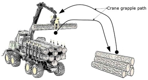
To improve the performance of cranes, it is important to understand which particular motions cranes can perform to minimize resource consumption. In the log loading process, for instance, a human-operator manages and chooses the crane’s movements more or less intuitively in order to perform a given task. While it might seem simple, given the simplicity of the individual movements involved, to decide the path the crane’s grapple should follow, for example, when loading and unloading a forwarder’s log bunk (see ), the real operator skill consists of synchronizing the independent boom joint movements, because for a given path (such as the one illustrated in ), there exists effectively an infinite number of ways to synchronize the joints, all leading to similar behavior. Additionally, a given task can be accomplished with many different paths, speeds, accelerations, energy levels, etc. Thus, the main challenge for a machine operator is to select motions from an unbounded number of choices for each of many possible three-dimensional paths, in such a way that the work is performed in the most comfortable, energy-efficient and profitable way.
Figure 1. Examples of crane grapple paths for a typical forwarder crane.
Since the motion of a forestry crane depends on the masses, the inertias, the forces acting on the system and the particular movements that are carried out, the choice of how to synchronize the individual crane-booms so that the grapple follows a particular path is a very important point to consider. For instance, if a fixed path to perform a particular task is chosen, an increase in productivity would require an increase in the velocity of the crane’s movements along this path. However, by increasing the operating velocity of the crane, the energy consumption (fuel, electrical energy, etc.) will also increase. Thus, the choice for a particular path becomes a trade-off between the velocity at which the task is performed and the resources consumed, where the ideal scenario is to perform the same task in the shortest feasible period using as little energy as possible.
One way to address this trade-off problem is to use concepts from the field of robotics, which is an area in which the optimal motion of mechanical systems plays an essential part. Different methodologies are available to plan optimal paths for mobile robots (Liu and Sun Citation2014), or to perform energy-optimal motions with industrial robots (Paryanto et al. Citation2015). Motion planning is a fundamental tool applied to industrial robots in order to minimize their energy consumption, because energy consumption is directly related to how a robot moves (Hirakawa and Kawamura Citation1997; Sezimaria and Ceccarelli Citation2004). The control systems implemented on robots are used to execute motions as planned. In contrast to motion planning, which is purely a mathematical subject, control systems require specific sensors and computing hardware to execute planned motions. In forestry, cranes are beginning to be equipped with sensing devices (position and pressure sensors) opening up the possibility of developing computer-assisted technology for cranes (Lindroos et al. Citation2017), which will make it possible to apply motion planning techniques, and thus develop semi-autonomous, or even fully autonomous crane operations.
Since options for loading and unloading tasks in forwarders with fixed log bunks are limited, researchers have proposed new designs for log bunks that increase the number of ways in which loading and unloading may be performed (Ringdahl et al. Citation2012). One such design is a rotating load bunk (harwarders), like the X19 prototype manufactured by Komatsu Forest. A rotating log bunk allows the crane grapple to follow a much wider range of paths when loading and unloading the log bunk (as illustrated in and ), which also increases the options for reducing energy consumption when loading and unloading.
Therefore, given the sensing technology available on forestry cranes, and the possibility of various path options for loading and unloading logs, there is both an opportunity and a need to perform motion analysis as a tool to increase performance. The objectives of the paper were the following:
To present a way to describe, model and estimate the energy consumption when the crane’s grapple follows a particular path.
To briefly present concepts of a particular motion planning technique to design energy-optimal motions.
To evaluate the effect on a crane’s energy consumption for the crane’s movements when a log bunk allows new paths for loading and unloading tasks.
The objectives were addressed by conducting a simulation-based comparison between two crane-bunk systems. For the purposes of this paper, the crane’s grapple follows a path from an initial given point to a point inside the log bunk area without collisions. Three specific paths were compared; a standard path for a conventional crane with a fixed load bunk (forwarder), and two possible different paths for a crane with a rotating log bunk (harwarder). The comparison takes into account dynamic and kinematic models, mathematical descriptions for the paths, and the optimal motion planning concept with three options for performance criteria.
Materials and methods
In order to evaluate energy consumption for the crane’s movements when considering motion planning, a simulation-based comparison between two crane-bunk systems was performed. To this end, this paper considers an in-house design desktop-size prototype, produced using 3D-printing in order to conduct research into automation. Therefore, the physical properties used for analysis – masses, actuator forces, inertias, etc. – belong to the desktop size prototype.
The main task is to move the grapple of the crane through a predefined path in three-dimensional space, as sketched in . The motion goes from an initial given point to a final point inside the log bunk without collisions, simulating a pick-and-place action of grabbing a log from the ground and placing it in the log-bunk. Three specific paths were compared: a standard path for a conventional fixed log bunk, and two different paths with a rotating log bunk. For this comparison, the framework involves the kinematic and dynamic model of the crane (without logs), the kinematic model of the log bunk, three specified paths and three performance criteria (total energy, torque and mechanical power). Being considered as constants in the evaluation (the same fixed extra mass in the grapple), the logs were not considered in the simulation, although the restriction related to having them in the grapple was included (i.e. having to pass over load stakes instead of between).
General description of the crane-bunk systems and the paths to be considered
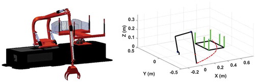
Two different systems were studied, both of which include a crane and a log-bunk. For each system, the crane’s grapple had to move through a path simulating the loading of logs into the bunk, without the logs or the grapple colliding with the bunk. The first system resembled a standard forwarder, where the log-bunk is fixed, while the second system resembled a harwarder, where the log-bunk can rotate. To facilitate comparison, the initial and final configurations for the motion of the crane were the same. Referring to , with the crane’s pillar in the Cartesian coordinates (0m, 0m, 0m), the Cartesian coordinates of the grapple’s starting point (for all cases) were (0m, −0.4m, 0m), while the Cartesian coordinates of the grapple’s ending point (for all cases) were (0.5m, 0m, 0,1m).
Figure 2. Schematic representation of a forestry crane with fixed log bunk (forwarder) and the standard path.
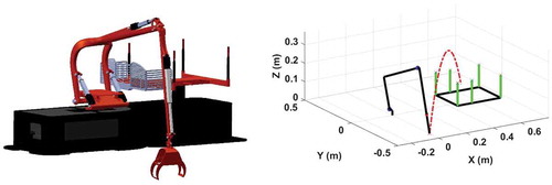
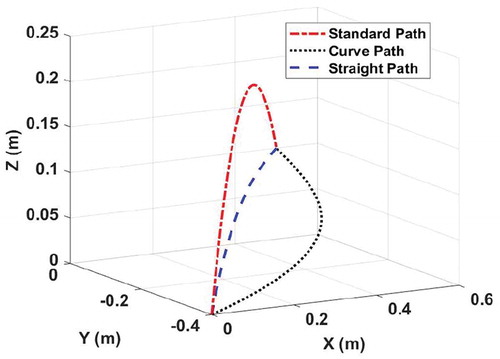
For the case when the machine behaves as a conventional forwarder, the path followed by the crane’s grapple resembles a parabola, as depicted in (hereafter called the “standard path”). For that motion, the grapple has to travel high above the log-bunk in order to avoid collisions with the log-bunk poles (, right).
A harwarder with a movable log-bunk allows other path options for the grapple, two of which were considered. The first path resembles a quasi-straight line, for which the final position of the log bunk forms an angle of 135° with the “X” axis (). The second path is represented by a curve with the final position of the log bunk forming an angle of 90° with the “X” axis (). Henceforth these harwarder paths are, respectively, called the “straight path” and the “curve path”. As shown in and , having a movable log-bunk removes the necessity of lifting the grapple over the log-bunk.
Figure 3. Schematic representation of a forestry crane with rotating log bunk (harwarder) and the straight path.
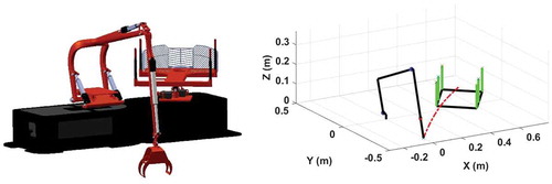
Figure 4. Schematic representation of a forestry crane with rotating log bunk (harwarder) and the curve path.
Mathematical modeling
Motion planning requires mathematical models of the crane, the log bunk, and a mathematical definition of the paths followed by the grapple. Since the energy consumption of the crane is taken as the main design criterion, it is necessary to derive the kinematic and dynamic models in order to calculate the energy that the crane consumes when performing a particular task. Clearly it is necessary to avoid collisions between the grapple and the log-bunk, so the position of the log-bunk must be known at all times. Thus, the kinematic model of the log bunk is also needed. Finally, paths followed by the grapple are defined by mathematical polynomial functions called Bézier curves (Mortenson Citation1999).
Kinematic model of the crane
A kinematic model is a set of equations that help to calculate the position and orientation for each of the rigid bodies in a mechanical system, without considering the forces that cause the motion. Four rigid bodies are considered in this study (). The base of the crane has rotational motion and is represented by . The inner boom and outer boom also have rotational motion, represented by
and
, respectively. Finally, the telescope has translational motion, represented by
. The variables
,
,
, and
are known as generalized coordinates and denote the main boom motions of the crane. The vector of generalized coordinates can be mathematically stated as follows,
Figure 5. Components of a forestry crane and the variables names for their generalized coordinates (-
).
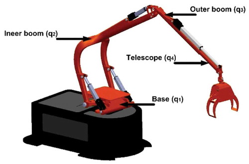
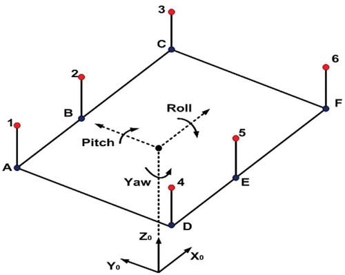
Figure 6. Elements for log bunk kinematics.
where is the transpose operator. Once the vector of generalized coordinates is given, the forward kinematics is obtained by means of the Denavit-Hartenberg (DH) convention (Spong et al. Citation2006). Forward kinematics make it possible to calculate the Cartesian coordinates (X, Y, Z) of the grapple’s location given the values for
. The inverse problem of computing
given the grapple’s Cartesian coordinates, known as the inverse kinematics, is solved using another set of nonlinear trigonometric equations. The use of forward and inverse kinematics makes it possible to determine the position and orientation of all components of the crane at all times.
Dynamic model of the crane
Unlike the kinematic model, the dynamic model is concerned with the study of forces and torques and their effect on the motion of the rigid bodies. The use of Euler-Lagrange formulations (Spong et al. Citation2006) leads to a general procedure for representing the dynamics of a crane as a system of second order differential equations. A general form to describe a mechanical system is given by,
where represents the vector of generalized coordinates, and denotes the position for each of the crane joints;
and
represent the first and second derivatives, denoting the velocity and acceleration of the motion, respectively;
represents the mass and inertia matrix,
represents the Coriolis matrix,
represents the gravity vector and
represents the vector of torques and forces exerted at the crane’s joints. Equation (2) considers the physical properties of the crane in terms of the positions, velocities and accelerations of each of the crane’s components (), as well as the individual masses and inertias. Having the values for all these physical properties and a defined motion for
allows
to be calculated, telling us the forces needed to generate that motion.
Kinematic model of the log bunk
The kinematics of the log bunk considers a flatbed and six retaining stakes (). The forward kinematics of the log bunk was considered in the Cartesian space and computed using the Yaw, Pitch and Roll Euler angles, as well as the Denavit-Hartenberg convention (Spong et al. Citation2006).
Mathematical description of the paths
– show only the shape of the paths. Nevertheless, mathematical equations representing the paths are necessary. The three paths were all mathematically described by means of Bézier curves as follows,
where,
In Equations (3) and (4), are the coefficients representing a polynomial of order n and
are control points for the Bézier curve. By defining different values for
and
in (3) and (4), the three paths shown in are obtained. Values for the arc length (measurements of the traveling distances along the paths) are given in .
Table 1. Arc length for each of the paths.
Figure 7. Comparison of the paths in Cartesian system.
Motion planning problem
The motion planning problem consists of finding the individual crane movements and
required to move the grapple from an initial to a final point along a given path. During the motion, the grapple should move along the desired path avoiding collisions, and the motion should respect the restrictions of the system in terms of velocity and acceleration. These restrictions come from the fact that the cylinders to move the crane will reach a velocity limit when using maximum power. Velocities above that limit are impossible, because the system cannot physically deliver more power.
Although motion planning has been extensively investigated since the beginning of robotics, there is neither a standard algorithm providing the best possible solution, nor an agreement on how to measure the performance of a computer generated motion. The problem lies in the redundancy in the number of degrees of freedom (number of generalized coordinates), which means that an infinite number of motions can accomplish similar behavior. Therefore, whether computerized algorithms perform well or not is subjective and depends on a variety of factors. These factors are related to the task for which the method is being used, and the performance metric applied by the motion-planning algorithm. There exist numerous methods to solve the motion-planning problem. A modern approach is to use optimization. Optimization methods are iterative processes attempting to maximize or minimize an objective function (e.g. energy), where the computational cost (i.e. time to solve the optimization problem) depends on the number of constraints and the number of independent variables. For the particular problem studied in this paper, the objective function could be stated as: maximize the velocity profiles along the established path, while minimizing energy. The independent variables would be and
and the solutions should fulfill the acceleration and velocity constraints, as well as the different conditions to avoid undesired collisions. The solution for this particular problem could use optimization methods of nonlinear programming with complex computational cost. The problem with standard optimization is that it often leads to long search times, and it is not possible to determine whether a solution exists or not.
A more sophisticated approach to motion planning uses virtual holonomic constraints (Ortiz Morales et al. Citation2014), which make it possible to solve the motion planning problem analytically. Analytical methods are usually superior to iterative methods, because they provide a direct solution to a problem without the need to run iterative algorithms for extended periods of time. In addition, virtual holonomic constraints allow for the selection of motions within the upper and lower velocity limits. Selecting motions near the maximum velocities represent the faster motions. Hence, the computational cost when using virtual holonomic constraints is less than that for optimization-based methods. As virtual holonomic constraints have more benefits than standard optimization methods, this method of motion planning was used in this study. Interested readers can find more information about the applications of virtual holonomic constraints in the area of automation for forestry cranes in the work paper by Ortiz Morales et al. (Citation2014) and the references therein.
Performance criteria
The motion planning solution determines the movements for and
, so that the crane’s grapple will follow a given path and complete it within a given time. Calculating the crane’s energy for the solution becomes readily available, because the motion planning procedure provides information about the positions, velocities, accelerations, and forces.
Using concepts from classical mechanics, total energy, torque and mechanical power are physical properties measuring energy consumption, and are often used for planning motions in robotics. These properties relate to the power actuators consume when performing motion, and are calculated according to the forces and torques required to perform a given movement. Thus, three energy-related performance criteria can be mathematically expressed using these physical properties as follows:
1) Total energy :
2) Torque :
3) Mechanical power :
Where represents kinetic energy,
is the potential energy and
is the vector of velocities, that is, the derivative of the generalized coordinate vector. Note the energy consumption of the crane (without logs) is considered but not that of the log-bunk, because the energy required to rotate the log-bunk is negligible in relation to the energy required to move the crane.
Analysis
Energy consumption was measured from the moment the grapple started the motion (at the initial position) to the moment it stopped (at the final point). The three paths were evaluated based on the three performance criteria, given a fixed amount of time to traverse the path. The average of the three criteria was also calculated for each path. The effect of time allowed to complete the path traversal was investigated, requiring simulations of different crane velocities. In the simulations, the shortest time to finish the motion was set to 30 seconds and the longest time was set to 70 seconds. The shortest time was chosen according to the constraints imposed by the actuators and the particular design of the desktop-size crane-bunk systems. Since there is virtually no limit to how slowly any motion can be executed, the longest time limit was set subjectively. For comparison purposes, the time span of 40 seconds was selected, since this time was considered fast while the amount of energy consumed was reasonable. Finally in order to give an example of the effect of only allowing given levels of performance criteria, the time required when allowing a mechanical power of 0.40 W was evaluated.
Results
The simulation results showed that for any given motion, there was a trade-off between speed and energy, with more energy required when executing the path in shorter time (). Irrespective of the time allowed for the work, following the standard path consumed most energy, regardless of the performance criteria (), while following the curve path consumed the least energy, irrespective of time allowed and performance criteria chosen. The amount of energy required, for an allowed time of 40 seconds, is shown in .
Table 2. Energy consumption for different paths at the trade-off point t = 40 seconds.
Figure 8. Trade-off between performance criteria and time when considering different paths. The x-axis represents the time it takes to finish the motion. The y-axis is the amount of energy consumed given the performance criteria, in both axes from the fastest motion to the slowest. The first column of plots shows results using the performance criteria of total energy (5), the second column using torque (6), and the third column using mechanical power (7). Note that the y-axis scales vary, in order to enable visualization of the trade-off pattern between time and energy.
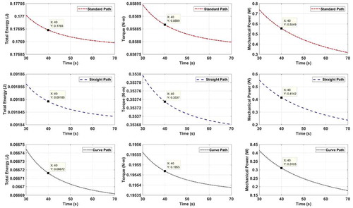
Taking the standard path as the reference point for total energy as performance criterion, approximately 48% less energy was required when using the straight path and 62% less energy using the curve path (see energy values in ). For the case of torque, the corresponding values were 58% and 77% less torque required for the straight and curve path, respectively. Finally, for mechanical power, the corresponding values were 25% and 44% less for the straight and curve path respectively. The average savings were 43% for the straight path and 61% for the curve path.
Given a fixed mechanical power of 0.40 W, the task was performed in 55 seconds when the standard path was used, while the task was performed in 31 seconds using the curve path. Thus, in a period of one hour, the task could be conducted approximately 65.45 times using the standard path and 116.12 times using the curve path. Thus, for this energy level, using the curve path would nearly double productivity.
Discussion
This study describes the mathematical foundations required to analyze certain characteristics of forestry cranes, in particular the energy consumed when a crane’s grapple follows a given path. Additionally, it presents a method to plan energy-optimal motions, clearly exhibiting the trade-off problem between velocity and energy for crane motions. Using this approach makes it possible to plan time-optimal motions with a trade-off between velocity and energy consumption. These results complement former studies that only showed how time-optimal motion can be determined (Ortiz Morales et al. Citation2014).
As explained above, improvements in energy consumption are related to improvements in mechanical performance: total energy, torque and mechanical power. These are physics-based criteria related to the dynamics of motion, i.e. how forces are applied to the crane in order to perform particular movements. An alternative choice is to use fuel as a measurement of energy consumption. However, the fundamental mathematics required to properly analyze this problem is not available in the literature, because fuel consumption involves highly nonlinear equations that are subjective and not general (Ogata Citation2003). Nevertheless, it is important to understand that reducing energy in terms of mechanical performance will reduce fuel consumption, since the system uses fuel to generate motion, and fuel is somewhat related to mechanical power.
In the field of automation, path planning remains a challenging area, because for any redundant mechanical system there exists not one, but a variety of paths that can be used to perform a similar task. This paper considers three paths selected as examples. The first is a standard parabolic path, performed by standard forwarder machines during typical working cycles. The second and third are provided as examples when a machine has the ability to work as a hardwarder, i.e. with a rotating log-bunk. This configuration was chosen because machines of a similar kind have been produced as prototypes in Scandinavia. Hence, the choice does not go outside the mainstream of industrial developments. Additionally, it is important to mention that selecting better path options is possible, but that requires a study of optimal path planning, which was outside the scope of this article.
The results show that using harwarder machines could reduce energy consumption by at least 43% (compared to using a forwarder machine), when the path of the grapple resembles a quasi-straight line (straight path). Further improvements, by at least 62%, may be achieved when the grapple follows a curve-like path. The reason why a harwarder-like system has greater productivity than a forwarder-like system is because the actuators do not need to make the extra forces to lift the crane above the log-bunk. Since the actuators are naturally holding the weight of the crane, most of the energy required to perform motion is wasted on lifting weight. In terms of physics, motions of the grapple above the log-bunk involve high potential energy, which is related to lifting weight. Note the additional energy consumed by the rotating log-bunk in a harwarder-like system is negligible in relation to the crane’s potential energy.
This study used an in-house design of a desktop-size prototype developed for automation research as the model for the analysis. The size of this system raises the question of whether the results are scalable to large machines. It is indeed, since forestry cranes are mechanical systems, and properties such as mass, inertia and forces are general irrespective of size. Given that this study involves a physics-based framework that has formerly been validated on commercial forestry machines (La Hera and Ortiz Morales Citation2014; Ortiz Morales et al. Citation2014), similar results can be attained with large machines. Thus, the results suggests further studies on the benefits of having rotating log-bunks on forwarders would be valuable. In addition, for the case of standard forwarders, future studies could address the optimal path planning problem in order to identify the path with the best possible trade-off between energy and velocity, in contrast to the arbitrarily chosen paths used in this study. Optimal motions can be used currently for the education of machine operators, and more technologically, they can be used to automate portions of the working cycles (Ortiz Morales et al. Citation2014). As mentioned before, paths selected in this paper were not necessarily the best options but they can provide a general idea of how the process can be improved. Taking into account that some of the actual cranes have the neccesary equipment to perform autonomous movements, it would be easy to carry out a test in order to verify the benefits of applying autonomous movements against movements perfomed by operators.
Finally, this study focuses only on the log loading process. Nevertheless, it is possible to analyze the logging operations using the same methodology, since all the operations are perfomed by means of mechanical devices. Hence, it is possible to derive models considering the dynamics of mechanical systems (cranes, vehicles and log bunks), physical properties of the logs (weight and size) and the extraction distance. Advanced optimization tools, such as those provided by virtual holonomic constraints, can then be used to solve particular problems that maximize or minimize different performance criteria.
In conclusion, this document showed that by considering a rotating log-bunk and energy-optimal motions, energy savings can be achieved. Since the results are based on mathematical models, the methodology can be implemented in real cranes and it can be guaranteed that the results will be similar.
Acknowledgements
This study was partly financed by the Swedish Energy Agency (project HAFSBiT, 48003-1), the Swedish Foundation for Strategic Environmental Research MISTRA (program Mistra Digital Forest), the Kempe Foundations (project JCK-1713) and the Swedish Cluster of Forest Technology.
Disclosure statement
No potential conflict of interest was reported by the authors.
Additional information
Funding
References
- Billingsley J, Visala A, Dunn M. 2008. Robotics in Agriculture and Forestry. In: Siciliano B, Khatib O, editors. Springer Handbook of Robotics. Berlin (Heidelberg): Springer.
- Fodor S, Freidovich L, Vázquez C. 2016: Practical trajectory designs for semi-automation of forestry cranes. Proceedings of ISR 2016: 47st International Symposium on Robotics.
- Gerasimov YY, Siounev VS. 2000. Forest machinery crane compound scheme synthesis: Optimization of hydraulic cylinder operating mechanism. Int J For Eng. 11(1):73–79.
- Häggström C, Lindroos O. 2016. Human, technology, organization and environment –a human factors perspective on performance in forest harvesting. Int J For Eng. 27(2):67–78.
- Hirakawa A, Kawamura A. 1997. Trajectory planning of redundant manipulators for minimum energy consumption without matrix inversion. Proceedings of the IEEE International Conference on Robotics and Automation. p. 2415–2420.
- Kalmaria J, Backman J, Visala A. 2017. Coordinated motion of a hydraulic forestry crane and a vehicle using nonlinear model predictive control. Comput Electron Agr. 133:119–127.
- La Hera P, Ortiz Morales D. 2014. Non-linear dynamics modelling description for simulating the behavior of forestry cranes. International Journal of Modeling. Identif Control. 21(2):125–138.
- Lindroos O, La Hera P, Häggstrom C. 2017. Drivers of Advances in Mechanized Timber Harvesting – A Selective Review of Technological Innovation. Croat J For Eng. 38(2):243–258.
- Liu S, Sun D. 2014. Minimizing energy consumption of wheeled mobile robots via optimal motion planning. IEEE-ASME T Mech. 19(2):401–411.
- Manner J, Gelin O, Mörk A, Englund M. 2017. Forwarder crane’s boom tip control system and beginner-level operators. Silva Fenn. 51(2), article id 1717. 10 p.
- Mortenson M. E. 1999. Mathematics for Computer Graphics Applications. Industrial Press.
- Nurmi J, Mattila J. 2017. Global Energy-Optimal Redundancy Resolution of Hydraulic Manipulators: Experimental Results for a Forestry Manipulator. Energies. 10:647.
- Ogata K. 2003. System Dynamics. Prentice Hall.
- Ortiz Morales D, Westerberg S, La Hera P, Mettin U, Freidovich L, Shiriaev A. 2014. Increasing the Level of Automation in the Forestry Logging Process with Crane Trajectory Planning and Control. J Field Robot. 31(3):343–363.
- Paryanto B, Bornschlegl M, Franke J. 2015. Reducing the energy consumption of industrial robots in manufacturing systems. Int J Adv Manuf Tech. 78:1315–1328.
- Ringdahl O, Hellström T, Lindroos O. 2012. Potentials of possible machine systems for directly loading logs in cut-to-length harvesting. Can J For Res. 42(5):970–985.
- Sezimaria F, Ceccarelli M. 2004. Effect of basic numerical parameters on a path planning of robots taking into account actuating energy. Mech Mach Theory. 39:247–260.
- Spong M, Hutchinson S, Vidyasagar M. 2006. Robot Modeling and Control. New York: John Wiley & Sons.