
Abstract
The largest modular stellarator Wendelstein 7-X (W7-X) has successfully passed commissioning and first phase of operation in Greifswald, Germany. The limiter configurations of plasma with 2.5 T of magnetic induction on the plasma axis produce already considerable loads (MN) in the W7-X systems. The sophisticated W7-X superconducting magnet system with its non-linear support system is instrumented with an extensive set of mechanical and temperature sensors. Measurement results showed that magnet system behavior is in good correspondence with original predictions from numerical models. However, several areas require modeling improvements and/or proper adjustment of parameters to reflect “as-built” situation. Moreover, high temperature dependence of strain gauge signal accuracy in the range below 10 K requires its compensation in order to avoid fault alarms during monitoring. The work is considered as benchmarking of numerical models and as a preparation for upcoming more demanding phases with longer plasma pulses to guarantee safe and reliable W7-X operation with different divertor configurations. Both results of W7-X measurements and implemented improvements as well as lessons learned so far are also given.
I. INTRODUCTION AND MOTIVATION
The largest modular stellarator Wendelstein 7-X (W7-X) has successfully passed commissioning and first phase of operation in Greifswald, Germany. The limiter configurations of plasma with 2.5 T of magnetic induction on the plasma axis were successfully tested and all project team goals for first operation phase 1.1 (OP1.1), are fully reached in 2015–2016. Besides main achievements summarized in it is also necessary to highlight that considerable generated structural loads (MN) in the W7-X systems were successfully endured.
TABLE I W7-X Achievements During First Phase of Operation
The stellarator with major radius: 5.5 m, minor radius: 0.53 m, total mass: 725 t has a complex five-fold symmetric magnet system (MS) comprising 50 non-planar (NPC) and 20 planar (PLC) superconducting coils. The magnet system has to provide a wide range of different magnetic field configurations with a maximum field of 3 T at plasma axis and with maximum currents up to 18 kA and 14 kA in NPC and PLC, respectively.
The high requirements regarding field symmetry and plasma study possibilities result in a sophisticated support system, tight tolerances, and advanced numerical modeling. The latter is a demanding task due to the complex 3D configuration. The main structural components of W7-X are presented schematically in .
Fig. 1. Fragment of global FE models of cryostat and magnet systems with identification of sensor positions.
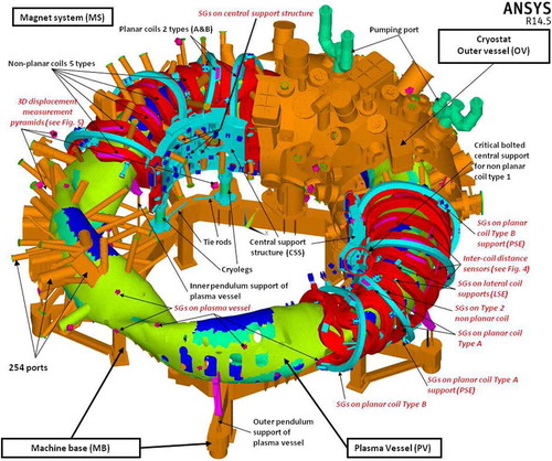
The complex support structure of the W7-X magnet system contains a large number of non-linear components (see and ) like sliding elements plastically deforming under design loads, bolted connections allowing flange opening and sliding, etc. The mechanical structure encompasses the central support structure (CSS) and the inter-coil support structure. The CSS stands on the machine base on ten cryolegs incorporating glass-reinforced plastic (GRP) tubes. Each MS module consists of two flip-symmetric half modules, but both the dead-weight and the cryolegs at the bottom of the MS break this stellarator symmetry. One half module includes five differently shaped NPCs (type 1, 2… 5 coils) and two PLCs (type A and B). Each superconducting coil is fastened to the CSS by two central support elements (CSE). The CSE is a bolted connection allowing possible opening of the flange. The narrow support elements and the lateral support elements connect adjacent NPC casings on the high field and on the low field sides of the machine, respectively. The narrow support elements are sliding contacts, while lateral support elements are welded connections with the exception of the inter-module ones which are bolted (see also ). The planar support elements (PSE) connect the two types of PLC to NPC type 2 and type 5. One PSE per coil (PSE-A1, PSE-B1) is a fixed bolted connection, while other PSEs follow the narrow support design.
Fig. 2. Fragment of magnet system global FE model with indication of main support types.
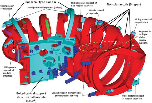
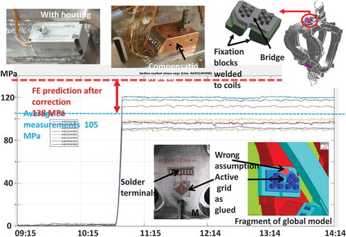
Fig. 3. Results of monitoring for bolted lateral support bridge (J-regime). Photo represents typical set-up for the SG sensors.Citation6 Bottom right fragment indicates original wrong assumption about SG position.
In addition to the superconducting coils a set of 5 normal conducting trim coils could be in operation to allow a fine tuning of the main magnetic field in order to influence field errors disturbing the toroidal periodicity.Citation1 The ramp up and down rate of the trim coil currents is up to 2000 A/s (CitationRef. 2).
Also the cryostat system is quite challenging from mechanical point of view considering the special geometry, different temperatures during operation and plasma vessel baking, as well as flexible and adjustable plasma vessel supports. The cryostat is standing also on a common steel structure machine base which has a finite stiffness. The cryostat system consists of the plasma vessel, outer vessel, the ports and, the machine base. 254 ports with different shapes (round, oval, rectangular) connect the plasma vessel to the outer vessel using bellows. Pendulum support of the plasma vessel and its horizontal centering system with pushing bolts against the outer vessel introduce non-linearity in the system behavior, especially during plasma vessel baking.
The cryostat system analysis, monitoring and main features of behavior during commissioning and first phase of operation are described in CitationRef. 3.
In order to assess reliably the mechanical integrity of these systems during design, assembly, commissioning and operation, global finite element (FE) models in ANSYS and ABAQUS were created and intensely used for the benchmarking of FE results.Citation4 The detailed local FE analyses of critical components ended up with a clear understanding that some parts of the structure are close to their structural limits. The large amount of non-linear components in the magnet system makes its behavior prediction challenging. Another complication for the analysis of the MS is elements with different order of stiffness (e.g. coil cases and flexible tie-rods). Non-linear geometry option is to be activated to get reliable results e.g. in tie-rods.
The following five steps structural analysis is usually required for the MS:
bolt preload and shrink fit of corresponding elements;
application of dead weight;
cooldown;
application electromagnetic (EM) load;
EM unloading.
Another unique feature of W7-X is an extended mechanical instrumentation (MI) system The MI system was introduced in order to confirm advanced calculation approaches and results, as well as to ensure safe operation. The MI with its roughly 800 sensors (see ) is a subset of the huge W7-X instrumentation system yielding altogether more than 3000 signals. In addition to the mechanical data, temperatures, current levels, hydraulic parameters, etc. are also collected. Their monitoring and evaluation are a key issue during device commissioning and operation in order to guarantee proper running of the machine.
TABLE II Location and Number of Mechanical Instrumentation Sensors
The next project team goals are the physics programs for operation phases OP1.2 (with an inertially cooled divertor) during August 2017–December 2018 and OP2 (with a water cooled divertor) from 2020. In case of the experiment success, an optimized stellarator is to be considered as a mature option for the fusion reactor.
II. CONCEPT
II.A. Strategy
Achievement of the above-mentioned goals is only possible with close interlink between the MI and numerical models. Therefore, it is necessary to directly monitor the critical components and to benchmark with these results the non-linear numerical models.
Main steps to achieve this goal have been formulated before commissioning and first phase of operationCitation5: improvement of MI monitoring, benchmarking and update numerical modeling, neglecting unimportant features in FE models to accelerate the analysis. The strategy was successfully followed with the results described below in Chapter IV.
II.B. Mechanical Sensors
The mechanical instrumentation is described in detail in CitationRef. 6. A summary table is repeated here (see and ). The selected and implemented sensors for the magnet system are fully compatible with the severe operational conditions.
Three main groups of the MI instrumentation were installed in W7-X: strain, distance change, and contact sensors.Citation6 Due to the quasi-static stellarator operation conditions a large signal recording time interval of 10 s is allowed.
II.B.1. Strain Sensors
Rosettes with two types of conventional strain gauges (Vishay type (WK-09-950RA-350) and TML type) have been installed on the coil cases either by manufacturers of the coils or by W7-X assembly team. Differential thermal expansion of surface materials and the grids are mostly compensated by a copper coated (50 µm) compensation block. Heating caused by thermal radiation is reduced by a stainless steel heat shield covering the complete sensor system; it also serves as mechanical protection (see photos in ). The EM field is also well compensated by the small distance of 5 mm between active and compensation grids.
II.B.2. Displacement Sensors
The primary goal of the global FE models is to predict the stiffnesses and displacements of components. The data is widely used by physicists for comparison with relevant measurements or for positioning of the sensitive diagnostic in relation to the magnetic field. Therefore, displacement sensors are of great importance. Two ranges of displacements were originally specified by FE analysis:
opening of connection flanges between structural components and sliding up to 3 mm;
relative distance changes between coils in the range up 20 mm.
Commercial strain-type displacement transducer CE-10SL with ±10 mm range has been chosen for these purposes and modified to uni-directional range of 20 mm by pre-loading, see . There are 70 of such latter devices installed in the machine in different locations with different directions.
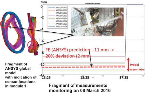
Fig. 4. Results of monitoring for maximum coils mutual displacements between NPC type 2 coils and PLC type A coils. Photo presents typical setup for the wire sensors.Citation6
Apart from displacement measurements of cold components of the magnet system, also the 3D-movements of the plasma vessel in relation to the outer vessel, and of all ten magnet system weight supports (cryolegsCitation7) need to be monitored. A special 3D displacement measurement unit of pyramid type has been developed on the basis of commercial cable extension transducers. A typical pyramid installed at the (warm) bottom of the cryoleg is presented in .
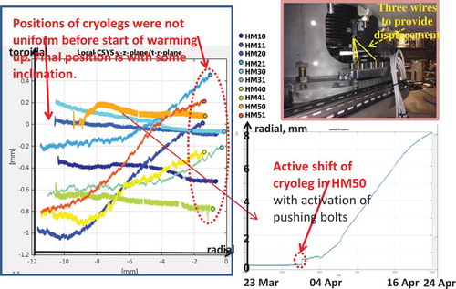
Fig. 5. Outward and toroidal movements of cryolegs during magnet system warming-up in 2016 with calibration file taken before cooldown in February 2015 (left fragment). Evolution of cryoleg radial sliding in half module 50 with an indication of active cryoleg pushing (bottom right). Photo (top right): Pyramid type displacement sensors.Citation6
II.B.3. Contact Sensors
In order to detect possible contacts between the magnet system and the cryostat, critical narrow gap areas are covered on one side with electrically insulated stainless steel foils with an applied voltage of 5 V. This way an electrical short due to contact between both components can easily be detected. During commissioning and operation no confirmed contacts were detected.
II.C. Sensor Locations
There is naturally a limited number of sensors which can be applied, and this is a compromise between effort and necessary information to be gained. The number and locations of strain gauges (SGs) on the coils were determined before start of coil production when the final loads were not yet known in all details. So some of these sensors are not on optimal positions but still yield valuable information. The locations of SGs on the structure elements as well as the displacement and contact sensors were determined later when all the critical regions were known in detail. First priority was given to instrumentation of critical components with well predicted stress levels, i.e. Inconel bolts of CSE connections under bending and tension.
Another critical region with expected yielding is on each half-module of the CSS where corresponding SGs are located. All other SGs are located in areas with moderate stress, mainly intended to support the FE model benchmarking.
Part of the MI sensors are distributed symmetrically over the five modules and the others asymmetrically in order to check the magnet system symmetry and to cover more locations, respectively.
II.D. Monitoring Approach
Due to MS complex structural design and a limited life time, each step of W7-X commissioning and operation is carefully monitored by a considerable amount of different sensors. Prior to the loading step a set of the boundary values for MI signals are established to distinguish nominal, questionable and critical state of the machine.Citation8
Real time monitoring of multiple sensor signals requires careful choice of the way to display the results. In case of MI, it is absolutely necessary to monitor temperatures in parallel with structural signals to avoid misinterpretation. Two or three levels of views, from minimum/maximum/average values down to the individual sensor signal, are found most appropriate. The monitoring software includes also signal filtering, and careful signal synchronization. The derived and implemented algorithms are a basis for a future deployment in a service oriented W7-X infrastructure. The program is flexible and could be deployed for tasks beyond the initial scope.Citation9
Unlike the fast machine control or the fast experiment data acquisition, the machine instrumentation works on a time scale of seconds to minutes and is not part of the W7-X control system. However due to availability of required electronics selected set of MI data is captured and stored within the W7-X experiment archive. Thus the provided data browsing and reporting tools are only of limited use when it comes to the approval of the structural integrity by mechanical engineers. In general, the assessment incorporates also reviews of FE analysis results.
III. COMMISSIONING, FIRST PHASE OF OPERATION AND THEIR MONITORING
III.A. General Remarks
All measurement systems have been tested in the laboratory under different test conditions before application to the respective components. Measurements with additional sensors (e.g. potentiometers for cryoleg movements), hydraulic cylinders, load cells and laser trackers have been performed in addition. It was found and accepted that reliable results are at the level of above 20 MPa and 1 mm for strain gauges and mutual displacements between coils respectively. Measurement pyramids have been more accurate (0.1–0.5 mm for different directions) and fully reliable. The monitoring activities with FE detail benchmarking analyses were carried out in parallel with stepwise loading of the individual W7-X sub-systems and components.
Some mistakes listed below have been found and corrected even in the middle of the individual coil group testsCitation5,Citation10:
Incorrect SPS programming;
Incorrect signal interpretation;
Inaccuracies in recalculation formulas and coefficients, etc.
This way the reliability of sensors is fully judged with regard to future, more demanding modes of operation.
Structural integrity of the magnet system with respect to electromagnetic forces is of main interest. Therefore, the signals had been set to zero when the operation temperature of ≈4 K is reached. Moreover, such zeroing had been done basically each time after temperature increase above 10 K. Later it was found that with such approach the residual stress could be neglected as well as the residual displacements, which are below 0.5 mm with exceptions for cryoleg sliding.
The expanded analyses, measurements and tests indicate the following most critical areas to be closely monitored:
GRP tubes of cryolegsCitation7;
Cracks in lateral support elementsCitation10;
One plasma vessel inner vertical supports has to be always under compression due to the detachment of the upper hinge;
Bolted lateral support between NPC type 5 (see and );
Central support of NPC type 1 (see indication in ).
Commissioning of the coil groups creates different load patterns therefore it has been performed with different maximum current levels (see ).
TABLE III Comparison of Acceptable Coil Current for Superconducting Coil Group Commissioning and Integral Test /OP1.1/OP1.2 Operation
III.B. Individual Tests of Superconducting Coils
Measurements with strain gauges rosettes installed on coil cases have been performed during the cryogenic coil acceptance tests carried out in Saclay, France. All 70 superconducting coils with originally installed Vishay type SGs and one planar coil after SGs replaced to TML type have been tested in self field. Several displacement sensors of cantilever type were also tested together with a planar coil in the test bed of Saclay. The analysis reveals the importance of calibration, compensation, signal filtering, and careful signal synchronization. There was generally reasonable correlation of signal values from SG rosettes attached on corresponding locations of the casted coil cases. However, some average values strongly deviate from the results of FE predictions.Citation5 One of the possible reasons for the deviation might be the small SG extension with respect to the big grain size of the non-planar coil casing cast material.Citation11 Within a grain the material is anisotropic with stiffness ratios up to more than two between principle directions. Since the actual orientation is unknown, equivalent stresses are calculated based on isotropic material assumption. In addition, due to the difficulty to control the orientation of SG rosettes with required high accuracy, it was decided to use for monitoring and comparison equivalent von Mises stress instead of strains in individual directions.
During the commissioning of the superconducting magnet system performed between April and July 2015 on 21 operational days,Citation2 it was found that deviations are much less than during tests in Saclay.
In any case, all the measured stress values are far below any critical one and thus the deviations are of no concern.
Stepwise commissioning of the magnet system components with full functionality for steady state operation was a great advantage for the FE model benchmarking performed in parallel. During integral test the current was stepwise increased until 12.8 kA in the NPC circuits and 5 kA in the planar coil circuits. At each level a fast discharge was initiated to release up to 430 MJ stored energy at maximum current level. The event is real shock for the MS, therefore a verification cycle has been performed after each fast discharge to confirm a structural integrity with MI sensors.Citation5
III.C. First Plasma Operation
The first operation phase of W7-X required a minimum magnetic field strength of 2.5 T on plasma axis at the area where the ECRH waves hits the plasma.
The great advantage of the first operation phase was the fact that the regimes have been repeated many times. The approach confirms that the MS is stable with no progressive slippage, except first loading cycles (see and ).
Fig. 6. Monitoring results for first cycles with high loading (2015) for the lateral support bridge at the module separation in comparison with numerical prediction of residual stress at the location highlighted by red circle on FE mesh (upper right).
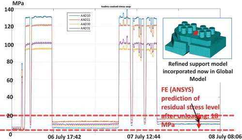
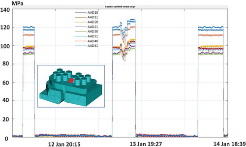
Fig. 7. Monitoring results for the lateral support bridge at the module separation (plasma cycles in 2016). Stress levels at the location highlighted by red circle on FE mesh.
The superconducting magnets were energized 35 times on 31 operation days for about 183 hours. The availability of the magnet system was approximately 94% (CitationRef. 2).
In accordance with FE prediction the following status has been already achieved:
70% of open narrow supports and 60% of planar supports respectively have been closed at 2.5 T “J-regime” and “A-regime”. The maximum compression force transmitted through narrow support is about 0.75 MN (67% of 3 T operation value), while PSE forces are still below 21% of maximum expected 3 T values. Just very local plastic deformations of the narrow support pads are to take place during OP1.1.
The most critical central supports have been loaded during OP1.1 by force well above 1 MN. However, if two most loaded supports are compressed (up to 2.1 MN), the critical support for coil type 1 (highlighted in ) is under 0.7 MN tension with a possible flange opening up to 0.2 mm at “A-regime”.
Lateral supports are also considerable stressed: three types of them transmitted forces above 1 MN (also about 67% of 3 T expected values).
Parallel to the superconducting coils a set of 5 normal conducting trim coils was operated at some days (e.g. 16th of February 2016), but an influence of the half current in the TC is only visible as small ripples on MI sensor signals.
III.D. Main Deviations
III.D.1. Structural
During supervision of the commissioning and operation by engineering team the most critical issue was the approval of further steps after observation of signal deviations from their predictions in the critical bolted connections at the boundary of magnet system modules. If higher stresses recalculated from strain gauge measurements in the corner of the fixation block could be explain by the fact that SG is located in the zone with high gradient and by variation of the friction factor,Citation5 the twice lower stress level in the bridge had no explanation. On the other hand, relevant sensors to monitor strains and displacements around the NPC5-5 region indicated no significant deviations. The study started during the operation was continued further for several months after completion of the campaign. It included the following steps:
review of previous parametric studies (narrow support and contact support gaps, material properties variation, etc);
improvements of lateral support modeling (see fragment of ) to reflect flexibility of bolted connection;
careful checking of relevant documentations.
It was found that neither realistic parameter variations could explain the measurements. Finally an inconsistency between CAD model and work instruction for the strain gauge application has been detected and the predicted values in the middle of the bridge converged to the observations (see ). The fact confirms again one of lessons learned, summarized and published,Citation12 that proper and consistent documentation of sensors types, parameters and locations is absolutely necessary.
The maximum measured mutual displacements up to 12 mm are between planar coil type A and non-planar coil type B (see ). The figure presents also typical deviations between FE prediction and measurements in different magnet system modules.
Non-uniform sliding of MS cryolegs is another point for close attention and to be carefully supervised daily during long cooling down and warming up. Generally, the supports have smooth sliding with a visible jump only after the static friction force was overcome. Few cryolegs had some delay (~2 mm). The most critical is the cryoleg in HM50 (see ). The reason could be years of resting at the same place during machine torus assembly and some degradation of sliding surfaces. Several cryolegs were pushed precautionary just before a long weekend with reduced personnel availability in order to avoid interruption of the processes.
High number of deviations between strain/displacement measurements and FE predictions are located in one module (module 3) of the magnet system. The asymmetry of sensor behavior is also peculiar to the module.
III.D.2. Flux Surface Measurements
The important indirect check of the MS deformation is a comparison of flux surface measurements (FSM) at different magnetic field configuration.Citation13 The prediction includes also FSM deformation of the coils from ANSYS FE model. The presently found deviation in rotation transformation for “J-regime” of the magnetic field is shown in .
Fig. 8. Flux surface measurements (FSM) (on the left) and rotational transformation of the magnetic field: measurements (bold dots) in comparison with FSM prediction based on FE deformation of coils (stars) (on the right).Citation13
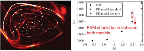
Next step is to compare results of measurement for “A-regime” configuration with zero current in the planar coils (see ) in order to exclude an influence of their less predictable behavior.
IV. FE ANALYSIS AND MONITORING IMPROVEMENTS
IV.A. General
The next operation phase OP1.2 with an inertial cooled divertor allows much higher input energy (up to 80 MJ) and longer pulse (up to 60 s with reduced power). Moreover it is expected that number of magnetic 2.5 T configurations is to be further extended. Both of these facts are considered in the present preparation activity.
Multiple operation cycles with higher energy could significantly increase the temperature of plasma vessel, parts of passively cooled ports and in-cryostat bellows. It is expected that much higher heat flux is to be delivered on the cryogenically cooled structures with corresponding increasing of temperature by few degree. This results in considerable SG signal changes.Citation5 In order to avoid false alarm and to guarantee smooth operation, it is necessary to implement a compensation of the effect using signals of temperature sensors located on the cryogenic structures.
IV.B. FE Global Model Improvements
IV.B.1. Improvement of Convergence for Structural Model
The “workhorse” of the engineering team is a magnet system global 72-degree FE model prepared in ANSYS. Original FE model prepared for commissioning and operation showed unstable convergence behavior in cases of change of ANSYS version or even small modifications. This required considerable not easy predicted efforts to make it run with reliable results. The situation has been found unacceptable and some actions have been made to overcome the problems and to run the model in ANSYS v17. The main steps are the followings:
Refined modeling of several supports (see and fragment of );
Fig. 9. Improvements of contact support modeling at module interface of global FE model of magnet system.
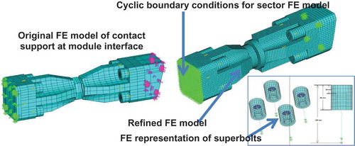
Fixation of rotational degree of freedom where applicable;
Application of shrink fit in cryolegs and module flanges of support rings as a gradually increased one during “Bolt-preload” step;
Optimization of solution settings.
The found drawback of the modified model is the required calculation time of approximately 100 hours to get a solution for all 4 loading steps. As a result a first level of the FE models includes:
Structural analysis ANSYS FE model: 100 hours model;
Verification electromagnetic FE model in ANSYS 1–3 hours.
Benchmarking FE model in ABAQUS and a set of local FE models structured in the model trees (approx. 200 in total). Each critical element of the MS has been analyzed with corresponding local FE models aiming not only to confirm structural reliability, but also to study its behavior.
Creation of second level FE models is on-going with the goal to simplify FE models to have 30 h to run all steps including EM unloading. The approach is based on reasonable neglect of second order effects (e.g. sliding for non-critical contacts, friction, detail force distribution, etc) to get the first impression about system behavior under new possible regimes during OP1.2 monitoring period. It is planned to re-create a 360-degree FE model on the basis of this simplified sector model.
IV.B.2. Inclusion of Unloading Step
The original approach of monitoring was based on signals zeroing after each change of MS temperature above 10 K. During intensive study of discrepancies discussed in Chapter III.C.1, first high loading pulses have been considered in detail with the conclusion that residual stresses due to some settlement of the non-linear system are present and also could be shown by the FE model (see ). As a result, the step with EM unloading has been added in the standard analysis of the MS.
IV.C. Monitoring Improvements
IV.C.1. General
The monitoring improvements are planned into two main directions: 1) to include better interpretation of the signals from the sensors (e.g. temperature compensation as described below), 2) to accelerate a process of comparison signals with three levels of criticality and/or to indicate location of the critical sensors.
IV.C.2. Temperature Compensation
Even after detailed consideration of SG measurements during cryogenic coil tests in Saclay, France, it was clear that the so called Kondo effect, i.e. a strong temperature dependence of the SG resistance, jeopardizes the measurements at the temperature region below 10 K.
Equation (1) shows the general relation between strain () and corresponding equivalent temperature (
.
presents an example of such compensation for two typical SGs after corresponding adjustment of parameters and
. The average temperature from all temperature sensors of corresponding coil is taken as a
value.
Fig. 10. Typical fit of strain gauge temperature dependence.
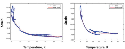
Corresponding measurement curves have been collected during commissioning and two cooldown/warming up to long standby mode (4 K -> ~ 100 K). The corresponding parameters are defined for each SGs and being implemented in monitoring software.
Moreover, such procedure could minimize number of zeroing procedure and allow tracking of possible residual stresses during cycling and in case of coil current configuration changes.
V. STATUS
Presently the numerical support is on-going with main focus on different diagnostic systems and the in-vessel components to be operated at high ECRH loads (port liners, cryo-pump, etc.). The open questions are to be solved now in order to initiate production of corresponding parts. The remaining open issue to be resolved before OP2 with an experience from OP1.2 is the protection of plasma vessel, diagnostics and in-vessel components from backside radiation of the plasma facing components.
Besides procedures are being implemented as mentioned in Chapter IV and urgent activities as described above, several issues are to be solved before the start of OP1.2. The most important question is an allowance to switch off the MS coil current during night shifts. The limitation here is a number of cycles, which is safely allowed for detected cracks in welded lateral supports of NPC (CitationRef. 10). The issue influences a choice of required supervision personnel for the phase.
The observation of buckling in several convolutions of the three-layer rectangular bellows under internal pressure triggered a procedure of regular check of the progress in the shape changes. At the moment there are no clear indications of progressive deformations, which are significantly above measurement accuracy, and any requirements for the next iteration of complex analysis.Citation5
The successful trim coils (TC) operation during OP 1.1 with half current showed that the system is a very powerful tool for the magnet field adjustment. It was decided to operate the coils up to maximum current during coming OP1.2. The TC commissioning with a full current is to be accompanied by and measurements and assessment of rubber pad behavior in the coil supports.
The collection and analysis of the MI signals are limited by number of expensive signal transformers needed to connect the sensors to the W7-X programmable logic controller system. The selection of sensors to be connected is the first task prior to each step of the commissioning and operation. The commissioning schedule requires re-plugging of the electronics and corresponding check of the signal chain from electronics to Web-interface of the CoDaC archive for the commissioning of cryostat components and each single coil circuit. Moreover information about not-recorded sensors are permanently lost, therefore a question about additional electronics is under consideration now.
The approach to derive conclusions about necessary modifications of FE model parameters (friction factor, stiffness, gaps, bolt preload etc.) from limited number of sensor measurements requires further careful development. It is expected that additional useful information will be collected during OP1.2 phase to realize an approach with minimization of deviations for several relevant sensors in the region using also probability for parameters adjusted in FE models.
VI. CONCLUSIONS
The following conclusions can be drawn from W7-X first phase operation activities:
Structural analysis strategy for next step of operation OP1.2 is developed and is being implemented;
Areas of most attention are defined;
Temperature compensation procedure is being developed and is to be tested during OP1.2 in order to be fully functioning during most demanding OP2;
Results of comparison between numerical modeling and mechanical instrumentation measurements during first phase operation show so far good agreement;
No limitation for the physics program is expected for already analyzed regimes. Some regimes with marginal deviations could be easily accepted,Citation14 others require analysis using first or second level FE models.
Some lessons learned during the W7-X first phase of operation might be relevant for other large fusion machines with extensive mechanical instrumentation:
Combined strategy for structural analysis and monitoring is to be developed, reviewed after each step of operation and implemented with a solid conclusion about limitations for the physics program;
Displacement measurements have higher importance for the monitoring of the machine behavior;
It is absolutely necessary to monitor mechanical signals in parallel with other machine parameters with a main focus on temperature changes and compensation of temperature influence on structural signals.
Acknowledgments
This work has been carried out within the framework of the EUROfusion Consortium and has received funding from the Euratom research and training programme 2014–2018 under grant agreement No 633053. The views and opinions expressed herein do not necessarily reflect those of the European Commission.
References
- K. RISSE et al., “Wendelstein 7-X Trim Coils—Component Safety Aspects and Commissioning Strategy,” IEEE Trans. Plasma Sci., 42, 449 (2014); https://doi.org/10.1109/TPS.2013.2294341.
- K. RISSE et al., “First Operational Phase of the Superconducting Magnet System of Wendelstein 7-X,” Fusion Eng. Des. (in press) (2017); https://doi.org/10.1016/j.fusengdes.2017.03.050.
- P. VAN EETEN et al., “Monitoring of W7-X Cryostat Commissioning with Cryostat System FE Model,” Fusion Eng. Des. (in press) (2017); https://doi.org/10.1016/j.fusengdes.2017.05.061.
- V. BYKOV et al., “Specific Features of Wendelstein 7-X Structural Analyses,” IEEE Trans. Plasma Sci., 42, 3, 690 (2014); https://doi.org/10.1109/TPS.2014.2302857.
- V. BYKOV et al., “Structural Analysis at the Transition from W7-X Construction to Operation,” IEEE Trans. Plasma Sci., 44, 9, 1722 (2016); https://doi.org/10.1109/TPS.2016.2594301.
- V. BYKOV et al., “Wendelstein 7-X Mechanical Instrumentation System for Commissioning and Operation,” Fusion Sci. Technol., 68, 2, 267 (2015); https://doi.org/10.13182/FST14-974.
- V. BYKOV et al., “Sliding Weight Supports for W7-X Magnet System: Structural Aspects,” Nucl. Fusion, 55, 5, 053002 (2015); https://doi.org/10.1088/0029-5515/55/5/053002.
- J. FELLINGER et al., “Preparation for Commissioning of Structural Sensors of Wendelstein 7-X Magnet System,” Fusion Eng. Des., 98–99, 1048 (2015); https://doi.org/10.1016/j.fusengdes.2015.06.041.
- A. CARLS et al., “A Structural Integrity Monitoring Tool for Wendelstein 7-X,” presented at 29th Symp. on Fusion Technology, Prague, Czech Republic, September 5–9, 2016.
- J. FELLINGER, V. BYKOV, and F. SCHAUER, “Assessment of Cracks in Lateral Supports of the Magnet System of Wendelstein 7-X,” Fusion Eng. Des., 88, 9–10, 1465 (2013); https://doi.org/10.1016/j.fusengdes.2012.11.021.
- M. SCHÜLKE, “Werkstoffanalyse Von Hochlegiertem Stahlguss Zur Herstellung Von Magnetspulen Für Das Projekt Wendelstein 7-X,” 1-GXB-T0020, IPP Greifswald (2010).
- F. SCHAUER et al., “W7-X Commissioning: Progress and Lessons Learned for Future Devices,” Proc. Symp. Fusion Engineering, Austin, Texas, May 31–June 4, 2015, IEEE (2015).
- M. OTTE et al., “Setup and Initial Results from the Magnetic Flux Surface Diagnostics at Wendelstein 7-X,” Plasma Phys. Control. Fusion, 58, 064003 (2016); https://doi.org/10.1088/0741-3335/58/6/064003.
- M. ENDLER et al., “Implementation of the Interpolation Between Load Cases,” 1-AA-T0057, IPP Greifswald (2016).