
 ?Mathematical formulae have been encoded as MathML and are displayed in this HTML version using MathJax in order to improve their display. Uncheck the box to turn MathJax off. This feature requires Javascript. Click on a formula to zoom.
Abstract
The largest modular stellarator, the Wendelstein 7-X (W7-X), has completed its second phase of operation, OP1.2, in Greifswald, Germany. The inertially cooled divertor installed between mid-2016 and mid-2017 has allowed a wider range of plasma configurations in comparison with the first operation phase, OP1. The sophisticated W7-X superconducting magnet system is further loaded up to 70% of its maximum design loads for all main components. The extensive set of mechanical sensors clearly shows a highly nonlinear system response, which is in rather good correspondence with the predictions from the available advanced numerical models.
However, there are also significant deviations observed in several areas. Therefore, modeling improvements and/or parameter variation analyses are necessary to clarify the issues in preparation for the upcoming, more demanding phase OP2 (2021+) with the actively cooled divertor and longer plasma pulses to guarantee safe and reliable W7-X operation.
The updated strategy to release multiple new plasma configurations being compatible with W7-X component design values is described briefly. In this approach, the numerical model linearization in the vicinity of an accurately analyzed point is a key method to accelerate the process and to highlight areas for vacuum field parameters not allowed for plasma operation due to structural criticality.
A brief overview of the W7-X measurement results, the observed deviations with numerical models, and the implemented improvements, as well as the lessons learned so far, are presented.
I. INTRODUCTION AND MOTIVATION
The largest modular stellarator, the Wendelstein 7-X (W7-X), has successfully completed the next phase of operation in Greifswald, Germany. The phase with inertially cooled divertor was divided into two parts: OP1.2a and OP1.2b, without and with scraper element to protect the pumping gap, respectively. The installation of the divertor in 2016 allowed for the exploration of the space of magnetic field configurations with 2.5 T of magnetic induction on the plasma axis to meet all project team goals and to achieve stellarator records.Citation1–Citation3
The focus of this paper is the fivefold symmetric magnet system (MS) comprised of 70 superconducting coils (see ) and its mechanical behavior during the second phase of operation. Five types of nonplanar coils (NPCs) and two types of planar coils (PLCs) provide the required field configuration flexibility for stellarator experiments. The fine-tuning of the main magnetic field is performed by five normal conducting trim coils (TCs). The progress from two main configurations during the first operation phase to 22 configurations with many variations and even with transitions between configurations without ramping down the current is to be highlighted as a great achievement (see ).
Fig. 1. Toroidal displacements under low iota 2.5-T EM loads in meters. (Last reference regime commissioned on June 28, 2018. Finite Element GM version 6.04: 5 × 1.4-M nodes.)
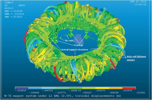
TABLE I Operation Phases, Achievements, and Future Goals
Besides the main physical achievements, it is necessary to mention that 70% of design structural loads in the W7-X systems have been successfully endured now for all main components. As a final step, double current levels have been successfully launched in PLCs and in TCs.
Toroidal displacements of superconducting magnets under electromagnetic (EM) loads peculiar to the last commissioned reference regime, low iota, are shown in . The specific feature of the configuration is a large positive current in both PLC types: 9.15 versus 5 kA during OP1.1.
Moreover, the behavior of the complex nonlinear support structure has been studied under different loading patterns for a large number of critical components (see Sec. II) using a unique feature of the W7-X: the mechanical instrumentation (MI) system with roughly 750 sensors. The system allows the confirmation of advanced calculation approaches and results, as well as guaranteeing safe operation. The only minor degradation from the first to second operation phases is the percentage of reliable mechanical sensors.
The coming project team goals are to install actively cooled in-vessel components including high heat flux elements and to perform the physics programs for steady-state operation phase OP2 (from 2021). The input energy from plasma heating is to be increased by approximately two orders of magnitude and 30-min pulses are to be demonstrated. The engineering task is to save the cyclic capacity of the machine, which is restricted by a few critical components. Therefore, a new operation sequence for operation week without the ramping down of MS currents is the scope of the nearest future work.Citation4
II. CHALLENGES OF NONLINEAR MS
II.A. General Remarks
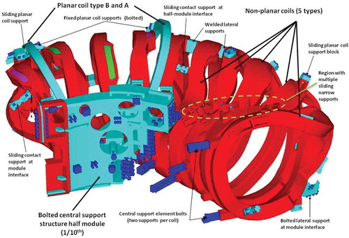
The nonlinear behavior of the W7-X MS is the main challenge for numerical modeling and monitoring. The main sources of nonlinearity in the W7-X MS are shown in and are listed here together with other MS features:
five types of NPCs with sophisticated three-dimensional configuration and two types of PLCs
complex and nonlinear coil support system
multiple bolted connections with expected opening
multiple contact elements with initial gap and gradual gap closing
just a few welded supports between NPCs
deadweight supports, so called cryolegs, with sliding/rotating at the bottom bearings installed on machine base; only toroidal tie-rods fix the position of the MS without restrictions for shrinkage during MS cooldown.
Fig. 2. Fragment of MS global FE model with indication of main support types.Citation7
As a result, there are elements with different orders of stiffness, and the nonlinear geometry option is to be activated to get reliable calculation results.
A detailed description of the different aspects has been published already during the design, development, and commissioning of the system.Citation4,Citation7–Citation13
Following assembly and commissioning, five steps are usually required for the full analysis of MS behavior. Four of them are pretty straightforward calculations comprising prestress, deadweight, cooldown, and EM loading. Due to requirements considering transitions from one regime to another, the fifth step has two options: either (1) to unload the model to catch residuals or (2) to load it further. Several cycles of load application are also possible to consider, e.g., they were used for the study of cryoleg tie-rod behavior.
The MI system, described in detail in CitationRef. 14, has three main groups of sensors: strain gauges, distance change, and contact sensors. The displacement sensors are of great importance because displacements of components affect both the plasma equilibrium propertiesCitation13 and the heat loads on in-vessel components. Part of the MI sensors are distributed symmetrically over the five W7-X modules and the others are distributed asymmetrically to cover more locations.
II.B. Monitoring Versus Numerical Predictions
A typical example of nonlinear behavior is presented in for the mutual displacement between PLCs and NPCs versus NPC current. Finite element (FE) prediction for the signal has clear double change of the inclination. The measurements are even more colorful and show typical displacement differences between modules and half-modules due to variation of contact element gaps and other mechanical parameters of the support system. However, if the average and error bars are taken, the correspondence is much better.
Fig. 3. Comparison between numerical prediction and measurements for coil mutual displacements between NPC type 5 coils and PLC type B during ramping up low iota coil currents. (a) Finite element prediction, (b) typical monitoring supervision results, and (c) post processing of monitoring results to show average signal and error bars.

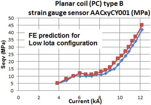
In addition, shows highly nonlinear FE prediction for the strain gauge on the surface of the PLC type B coil case. There are no big differences between half-module results for the signal, which is usually the case due to stellarator symmetry.
Fig. 4. Finite element prediction for PLC type B coil case von Mises stress (recalculated from strain gauges rosetteCitation4) during ramping up low iota coil currents. The location of the sensor is shown in ; the two lines represent two half-modules similar to .
III. IMPROVEMENTS OF STRATEGY
III.A. General Remarks
Due to the requirement to deliver accurate results on one side and to analyze a considerable number of proposals from physicists on the other, the present numerical analysis strategy is based on (1) gradual refinement of the model in specific areas to make monitoring prediction better and (2) using linearization, if current deviation from the already calculated regime is small.
III.B. Finite Element GM Refinements
presents the full FE global model (GM), which is too heavy for the regular analysis. Therefore, the “workhorse” of the engineering team is an ANSYS 72-deg GM analyzed with cyclic boundary conditions.
The main improvements are presented in CitationRefs. 7 and Citation12, while recent activities have been devoted to the introduction of model refinements in order to deliver more accurate signal predictions. Each operation campaign is followed by special activities to clarify discrepancies with measurements, including a few parametric studies to see their influences on the monitoring.
Two main reasons for discrepancies have been identified so far: (1) course mesh and (2) distances between sensor positions and nodes in use for FE result extractions. A typical example of the mesh refinement for fixed welded supports between NPC type 3 and 4 is presented in .
Fig. 5. Typical example of FE model of welded lateral support.
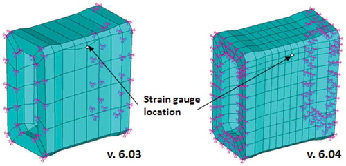
General achievement in the present version of ANSYS GM (v.6.04) is the following: deviations between all specified sensor positions and FE result extraction nodes below 20 mm.
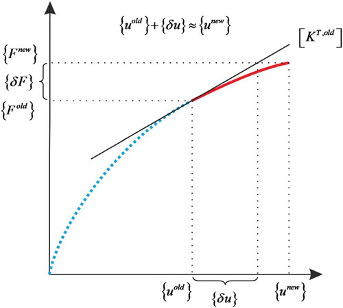
III.C. Global Model Linearization
The coils in the MS are overconstrained and distributed EM loads are variable along the coil axis, therefore structural response is difficult to predict even for small current variations. The linear perturbation analysis is an in-built capability of ANSYS, but it requires the usage of only the elements that are presently supported by ANSYS. The GM version 6.03 was not appropriate for the technique, therefore migration to the new GM version was necessary. The linearization procedure is implemented as a restart from the last load step 4 of an already calculated regime. A graphical representation is shown in . The transition to new element types has been done during OP1.2a and intensively tested to determine current variations acceptable for the prediction with required accuracy (see Sec. IV). As a result, the approach was intensively used during OP1.2b as shown in . Two-thirds of the variations have been analyzed with the help of the perturbation analysis.
TABLE II Types of Analyses for OP1.2a and OP1.2b
Fig. 6. Schematic view of linearization.
IV. VALIDATION OF NEW REGIMES
A fast validation procedure to deliver one of two possible conclusions, namely, new regime is safe or the regime is not allowed for W7-X, starts to be critical for the successful physics program as soon as variations are defined on a weekly or even daily basis after semiautomatic evaluation of physics achievements.
The input defined by physicists for the numerical engineering analyses is a set of coil-group currents and the induction on plasma axis. The general strategy for the approval or rejection of a proposal is presented in . The first branch is an easy acceptance, if current deviation per coil is within ±2% or ±40 A in PLCs (due to many regimes with zero PLC currents), which is safe and allows for reuse of the already prepared data for MI monitoring. However, the current deviations for the new regime are calculated only from the configurations accepted by full analysis. This restriction is necessary to avoid stepwise divergence from the accurate results. Previous acceptance approaches used 10% rulesCitation12 for the easy acceptance, but 7% exceedance of 2.5-T design values was found later after refined analyses of OP1.2a regimes.
Fig. 7. Filtering of configuration proposals from physicists after improvements following OP1.1 and OP1.2a.
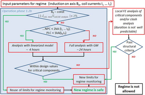
If the easy approval is not applicable, the possibility of using the linearized model is to be checked. Delivering results with the linearized finite element model requires 4 h, if differences for coil currents are within predefined limits. Otherwise, a full analysis within 24 h is necessary.
The results of either analysis are to be checked to guarantee that the generalized forces and moments in all supports and components, as well as displacements, are within design values. If yes, the regime is safe, but new limits for monitoring are to be prepared as indicated in the central branch of the diagram.
In the worst case, if the GM results are not within design values local analyses of critical components and/or clash analysis are to be launched. The time period for such complex and sometimes nonlinear elasto-plastic analysis is difficult to predict, therefore it is agreed during second phase of operation to permit only regimes satisfying the two first branches of evaluations with the GM.
V. LIMITATIONS OF OPERATION
V.A. General
The design of the complex magnet support system, reinforcement of critical components, and their optimization in terms of gap specification were mainly done using EM loads peculiar to four reference regimes. Later, the structural reliability and the absence of component clashes with predefined remaining gaps to cover tolerances of manufacturing and assembly were confirmed for nine reference vacuum configurations.Citation15 However, development of detail physics programs, accurate consideration of plasma currents, and issues related to plasma heating reveal that the initial configuration set needs to be extended. The extension is not always possible; therefore, two typical limitations found so far are discussed in this section.
V.B. Iota Scan
The first limitation for plasma parameter variation has been found during the study of transitions between three reference configurations: high iota, standard, and low iota.
In spite of the fact that all three reference regimes are fine during loading from zero to maximum current, there is a region of currents between high iota and standard in which EM loads result in overloading of few pins of PLC casings.
The possible reason, as assumed now, is that PLC bending is a superposition of bending induced by NPCs through fixed and sliding supports and deformation due to EM forces from current in the PLC itself. Sometimes the effects compensate each other, but sometimes not.
V.C. Minimization of NBI-Induced Heat Loads
The second limitation for plasma parameter variation that has been indicated during the study of best regimes for a minimization of loads induced by neutral beam heating on in-vessel components.
The problem is well visible on the plane characterized by the configuration mirror ratio along the x-axis and the radial plasma position on the vertical axis (see ). The corresponding current ratios are presented schematically for five NPC types and two PLC ones. The mirror ratio is a ratio between double magnetic field difference to average field on axis:
Fig. 8. Example of MS structural limitations for 2.5-T regimes proposed for NBI operation with minimum fast ion impact on in-vessel components.Citation16
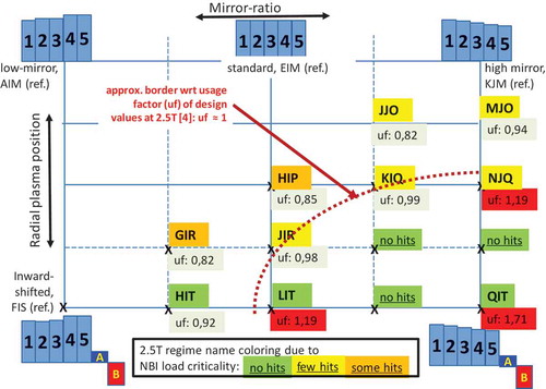
while the plasma radial position is controlled by currents in the PLCs.
Four reference configurations (low mirror, standard, high mirror, and inward shifted) are located along the axes. An analysis of neutral beam injection (NBI) loadsCitation16 showed that preferable regimes (indicated by green color in ) are in the far corner from the reference configurations. A detailed structural analysis confirmed that 2.5-T usage factorsCitation4 are close to 1 or far above allowable values in these cases. It is worth mentioning that the QIT regime is not acceptable even with 1.7-T inductance on the plasma axis.
During operation, it was agreed to not use the region beyond the border roughly indicated for 2.5-T design values by the red dashed line in .
VI. FAST DISCHARGES FROM HIGH CURRENT LEVELS
Another critical issue is a superconducting coil fast discharge from high current level (see ).
TABLE III Fast Discharge Events from High Coil Current Levels with Their Consequences
Monitoring results from the first operation phase indicated well visible degradation of the central support bolt preload. Detailed analyses highlighted that fast discharges are a possible reason for that. Therefore, it was decided that parameters for fast discharge with power supply test purposes are to be relaxed. Indeed, the bolt preload degradation has been reduced during the first part of the second phase, but other problems induced by fast discharges were found: issues with sensors [see consequence for the limiter (July 06) and the high iota (Aug. 24) configurations in ]. The first problem (four strain gauge sensors in one region of PLC AAC31) still has no clear explanation. The second problem (strain gauge AAD11HH901 on welded lateral support) is a clear sensor detachment confirmed by the warming-up/cooldown cycle afterward.
It was agreed to further reduce the current level for tests, but unfortunately, two real fast discharges from high current level took place during the summer campaign of 2018. The analysis of the event dated August 16 showed that the bolt preload loss was initiated again.
VII. CRITICAL COMPONENTS AND ISSUES
The critical component/issue list is not changed much from the one after the first phase of operationCitation12:
central support bolt preload degradationCitation7,Citation10,Citation12
glass-reinforced plastic tubes of cryolegsCitation8
cracks in lateral support elementsCitation9
bolted lateral support at module interface with some sliding developmentCitation12
measured displacements exceed FE predictions in some configurations.Citation12
The relevant components require permanent monitoring during MS operation. Therefore, the original set of electronics to capture and store sensor signals in the W7-X experiment archive was gradually extended. Finally, it was possible to avoid the re-plugin of electronics for several months of operation and to minimize signal deviations due to the procedure.
In addition, the project discusses some possible measures to correct the issues listed below:
degradation of rubber pad prestress in TC supports by removal of preinstalled shims and retightening
minimization of fast discharge impacts by further limitation on test events and better adjustment of quench detection system
degradation of cryoleg friction capabilities by lowering/lifting of few supports.
Further engineering issues are published in CitationRef. 17.
VIII. CONCLUSIONS AND LESSONS LEARNED
The following conclusions can be drawn from the two W7-X operation phases:
The results of comparisons between numerical modeling and MI measurements show good agreement after introduced modifications in the numerical models.
The areas of most attention are defined.
The approach for the fast and reliable approval of the regular extension of the physics program is further improved.
The gradual degradation of sensors requires full benchmarking/improvement of the FE model in the nearest future.
Further detailed analyses of W7-X cyclic behavior in preparation for steady-state operation are still ahead, but no major changes in strategy and approaches are expected.
As is highlighted in this paper, a considerable number of plasma configurations are beyond the original (reference) ones considered during the W7-X design and assembly phases. Therefore, a clear lesson learned could be formulated as the following: Development of a complex experimental fusion machine with a nonlinear support system should be based on an extended set of foreseen configurations to have the required physics parameter flexibility during operation.
Acknowledgments
This work has been carried out within the framework of the EUROfusion Consortium and has received funding from the Euratom research and training program 2014–2018 under grant 633053.
References
- T. KLINGER et al., “Technical Challenges and First Operation of the Wendelstein 7-X Superconducting Stellarator,” presented at 23rd Topl. Mtg. Technology of Fusion Energy (TOFE 2018), Orlando, Florida, November 11–15, 2018.
- T. KLINGER et al., “Overview of First Wendelstein 7-X High-Performance Operation with Island Divertor,” presented at 27th IAEA Fusion Energy Conference (FEC 2018), October 22–27, 2018, Gandhinagar, India.
- T. S. PEDERSEN et al., “First Divertor Physics Studies in Wendelstein 7-X,” presented at 27th IAEA Fusion Energy Conference (FEC 2018), October 22–27, 2018, Gandhinagar, India.
- J. FELLINGER et al., “Preparation for Commissioning of Structural Sensors of Wendelstein 7-X Magnet System,” Fusion Eng. Des., 98–99, 1048 (Oct. 2015); https://doi.org/10.1016/j.fusengdes.2015.06.041.
- K. RISSE et al., “The Magnet System of Wendelstein 7-X Stellarator in Operation,” Fusion Eng. Des., 136, 12 (2018); https://doi.org/10.1016/j.fusengdes.2017.12.008.
- T. RUMMEL et al., “Wendelstein 7-X Magnets: Experiences Gained During the First Years of Operation,” Fusion Sci. Technol. 75 (2019); https://doi.org/10.1080/15361055.2019.1629248.
- V. BYKOV, “Engineering Challenges of W7-X: Improvement of Numerical Modeling and Mechanical Monitoring After Commissioning and First Phase of Operation,” Fusion Sci. Technol., 72, 546 (Nov. 2017); https://doi.org/10.1080/15361055.2017.1352427.
- V. BYKOV et al., “Sliding Weight Supports for W7-X Magnet System: Structural Aspects,” Nucl. Fusion, 55, 5, 053002 (2015); https://doi.org/10.1088/0029-5515/55/5/053002.
- J. FELLINGER, V. BYKOV, and F. SCHAUER, “Assessment of Cracks in Lateral Supports of the Magnet System of Wendelstein 7-X,” Fus. Eng. Des, 88, 9–10, 1465 (Oct. 2013); https://doi.org/10.1016/j.fusengdes.2012.11.021.
- V. BYKOV et al., “Structural Analysis at the Transition from W7-X Construction to Operation,” IEEE Trans. Plasma Sci., 44, 9, 1722 (Sep. 2016); https://doi.org/10.1109/TPS.2016.2594301.
- V. BYKOV et al., “Specific Features of Wendelstein 7-X Structural Analyses,” IEEE Trans. Plasma Sci., 42, 3, 690 (Mar. 2014); https://doi.org/10.1109/TPS.2014.2302857.
- V. BYKOV et al., “Mechanical Monitoring Issues in Preparation to Next Step of Wendelstein 7-X Operation,” Trans. Plasma Sci., 46, 5, 1086 (2018); https://doi.org/10.1109/TPS.2017.2786744.
- T. ANDREEVA et al., “Influence of Deviations in the Coil Geometry on Wendelstein 7-X Plasma Equilibrium Properties,” Fusion Eng. Des., 123, 129 (Nov. 2017); https://doi.org/10.1016/j.fusengdes.2017.04.030.
- V. BYKOV, “Wendelstein 7-X Mechanical Instrumentation System for Commissioning and Operation,” Fusion Sci. Technol., 68, 2, 267 (Sep. 2015); https://doi.org/10.13182/FST14-974.
- T. ANDREEVA et al., “Characteristics of Main Configurations of Wendelstein 7-X,” Prob. At. Sci. Technol. Ser. Plasma Phys., 4, 45 (2002); https://vant.kipt.kharkov.ua/ARTICLE/VANT_2002_4/article_2002_4_45.pdf.
- S. AKASLOMPOLO et al., “Predictive Modelling of NBI Ion Wall Loads in the W7-X Stellarator,” Nucl. Fusion, 58, 8, 082010 (2018); https://doi.org/10.1088/1741-4326/aac4e5.
- H.-S. BOSCH, “Engineering Challenges in W7-X: Lessons Learned and Status for the Second Operation Phase,” IEEE Trans. Plasma Sci., 46, 5, 1131 (2018); https://doi.org/10.1109/TPS.2018.2818934.