
 ?Mathematical formulae have been encoded as MathML and are displayed in this HTML version using MathJax in order to improve their display. Uncheck the box to turn MathJax off. This feature requires Javascript. Click on a formula to zoom.
Abstract
Reactor plasma core fueling requires the injection of cryogenic pellets, most probably composed of a mixture of D2 and T2. Likely, pellet injection will be the most important actuator for plasma core density control. Therefore, pellet injection systems must be developed further that are capable of acting as actuator for density control. A novel control scheme is developed based on a centrifuge acceleration system. This scheme considers every available pellet launching slot and compares the current particle flux with the requested one. The response time is within the granularity of the available launching slots, in this case between 7 and 12 ms. First plasma experiments in feedforward mode showed excellent results, providing a good basis for upcoming plasma core density feedback control development activities.
Keywords:
I. INTRODUCTION
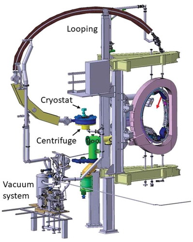
A future fusion reactor will need pellet injection for core fueling in order to overcome the Greenwald density boundary.Citation1 Hence, conventional pellet injection using cryogenic pellets made from a mixture of D2 and T2 will be a main actuator for the plasma core density. The huge particle content of a pellet (~2 × 10²¹ atoms) has a big impact on the plasma and the corresponding diagnostics. In particular, the pellet resilient measurement of the plasma density is a crucial task in order to allow for a safe and reliable actuation. An adequately designed control loop is therefore needed in order to achieve high-density operation while keeping good plasma conditions in a future fusion reactor. Recent progress in the development of suitable control algorithmsCitation2 pointed to the demand for a more suitable control scheme for the pellet injector at ASDEX Upgrade. The pellet system at ASDEX Upgrade is based on a single batch cryostat as pellet source, a centrifuge acceleration system, and a looping-type guiding tube delivering pellets to the magnetic high-field side of the plasma (see ) (CitationRef. 3). The pellet injection to the magnetic high-field side is considered a prime candidate for fueling the EU-DEMO (CitationRef. 4).
Fig. 1. Pellet injection system composed of cryostat unit, centrifuge launcher, looping-shaped guiding tube, and vacuum system located in Seg 5 of the ASDEX Upgrade vessel
The main advantage of a centrifuge-type acceleration system is its precise pellet speed. Hence, the arrival time of the pellets at the plasma can be predicted accurately. Pellets can be launched once per acceleration arm revolution, thus the repetition rate and the pellet speed are dependent parameters. Furthermore, the pellet production must be synchronized with the centrifuge rotation.
The acceleration process starts in the acceptance area of the stop cylinder. The pellet source delivers the pellet there by dropping it in. The inner rotating arm (part of the rotor) catches the pellet and puts it against the stop cylinder wall due to the centrifugal force. At the stop cylinder wall, the pellet has the same angular speed as the rotor but no radial speed. Entering through the stop cylinder slit hole the centrifugal force drives the pellet through the groove, and due to this form-closure-type acceleration, the muzzle speed scatter is very small.Citation5
The maximum cutter frequency limits the performance of our batch pellet source, being 83 Hz. For steady-state extruders, the maximum extrusion speed limits the maximum throughput and hence the maximum pellet repetition rate. That is why the combination of several extruders is a probable solution in order to meet the flux requirements.
In the framework of the Broader Approach enhancement project for JT-60SA, activities have been launched to create a suitable pellet launching system. Such a system will offer the opportunity to combine several pellet sources for fueling and pacing on one single centrifuge.
II. ACTUATOR CONCEPT
A running centrifuge provides a slot for pellet launching for each acceleration arm once per revolution. The ASDEX Upgrade centrifuge is equipped with just one useable acceleration arm. The second arm is for symmetry reason and balancing only.
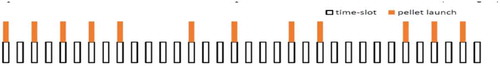
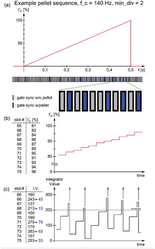
The basic idea of the new actuator concept is to identify available pellet launching slots and offer them to the control system. The algorithm is as follows: Initially every slot is available once per revolution. After using one slot for pellet launch, during the following time window of 12 ms the pellet source is busy preparing the next pellet. Hence, the next slot after this time period is declared to be not available (see ).
Fig. 2. Example layout of available launching slot concept. The centrifuge runs with 140 Hz, hence every 7 ms a possible slot occurs. In case an available slot is occupied by launching a pellet, the next slot will be available when the minimum cycle time of 12 ms has elapsed. In this example, at least one time slot must be left free. After the fifth launched pellet, the particle flux demand decreases in this example, hence some possible slots are not used
III. REALIZATION AT ASDEX UPGRADE
Pellet penetration into the plasma depends on the pellet speed. For a given plasma scenario, higher pellet speed causes deeper penetration and hence better fueling efficiency. On the other hand, mass loss on the pellet during transfer in the looping-type guiding tube increases with speed, as the mass erosion rises due to enhanced centrifugal forces.
As a good compromise, the AUG centrifuge usually runs at 140 Hz, providing a launching slot every 7 ms. The according pellet speed is 560 m/s. The maximum period to react to a controller pellet launch command is 7 ms, but for the next 12 ms, no slot can be occupied due to the nonavailability of pellets. The next usable pellet launching slot is 14 ms later, resulting in a maximum repetition rate of 70 Hz for continuous operation.
EquationEquation (1)(1)
(1) describes the metric number m depending on the time span ΔtPS, which the pellet source needs to produce a new pellet, and the centrifuge revolution frequency fc:
For values of m up to 1, every launching slot can be occupied; for values higher than 1 and up to 2, every second slot, and from 3 up to 4, every third slot. The ASDEX Upgrade centrifuge, as example, for frequencies up to 83 Hz, no launching slot must be left free waiting for the next pellets, from 83 up to 166 Hz, a single slot, from 166 up to 250 Hz two slots, and above three slots.
For safety reasons, the pellet operator sets the maximum repetition rate, considering further aspects like machine safety and physics. This limit is taken as 100% of pellet particle flux and cannot be surpassed by the discharge control system (DCS).
This concept abandons the up to now used concept of predefined repetition rates, which turned out to be not precise and fast enough for this control task.Citation3
A fast programmable logic control (PLC) module is used with a cycle time of 1 µs (SIMATIC FM352-5). This module controls the ice feed and the cutter activity, including synchronization with centrifuge rotation.
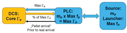
The connection to the ASDEX Upgrade DCS is realized similar to gas injection valves. The DCS requests a dedicated flux as a fraction of full scale. The full-scale flux is calculated by the maximum pellet repetition rate (due to the centrifuge speed) multiplied by the pellet size. Both values are set by the pellet operator and read out by the DCS before each discharge. This flux must be calibrated taking into account the nominal particle flux of the pellets reduced by the mass losses during acceleration and during the transport through the guiding tubes. The resulting particle flux is in the range of 60% to 80% of nominal value (see ).
Fig. 3. Setup at ASDEX Upgrade: The pellet source defines the pellet mass mp and the launcher the maximum pellet repetition rate fp. The PLC calculates the maximum particle flux: ГP = mP × fP,max. The DCS requests a fraction of this maximum particle flux (0% to 100%)
The set point for the particle flux is provided by the DCS using a 7-bit optical parallel link to express the 0% to 100% range. In case the calculated time interval between two pellet launches is shorter than the time elapsed since the last pellet launch, the next available launching slot will be used. This ensures fast response of the pellet system to set point changes by the DCS.
A refined variant of the Sigma-Delta modulator algorithm selects the pellet launch slot, with the set point for the particle flux rate as input (value: 0% to 100%) (CitationRef. 6). The gate sync signal of the centrifuge announces an imminent launch slot and clocks the modulator (value: 0 or 1). Hence, every gate sync activity increases the integrator value by the current set point value. The maximum pellet repetition rate depends on the centrifuge frequency. For a centrifuge running at a frequency of 140 Hz, the minimum metric factor to get the threshold value is 2 in order to meet the 12-ms time interval requirement, resulting in a maximum pellet repetition rate of 70 Hz. This fact is mapped in the algorithm; we obtain the threshold value by multiplying the metric value with 100%.
The pellet launch activity (value = 1 if activated) is multiplied with the threshold value and then subtracted from the integrator value (feedback), see .
Fig. 4. Block diagram of the Sigma-Delta modulator algorithm. Each gate sync event loads one actual set point value into the integrator. This value is compared with the threshold, which is equal to 100 times the metric value m. Each pellet launch is fed back to the entrance of the integrator, which subtracts the threshold value from it
A flux rate in the range of 1% to 99% results in a pellet sequence approximating the set point value averaging over some pellet launches (see ).
Fig. 5. (a) Example illustrating the integrator value during a ramp up of set point. (b) The continuously increasing ramp is transformed into a step function, keeping the value from one gate sync to the next one. (c) This value is added to the integrator value. With the integrator value passing the threshold, a pellet launch is initiated and the threshold value (here: 200) is subtracted from the integrator value
With 100% as the flux rate set point, the new algorithm exactly reproduces the formerly used algorithm, which did launch pellets on every n’th gate sync, with several predefined parameter sets (number of pellets and divider n).
The value of 0% for the particle flux input is a special case: It preloads the integrator of the Sigma-Delta modulator algorithm with maximum flux rate up to just below the threshold value, taking care to obtain the minimum time span ΔtPS. Any flux rate >0% sampled on gate sync immediately launches the next pellet.
This control scheme provides the option to integrate several pellet sources on one centrifuge. As a first step, fueling and edge-localized mode (ELM) pacing sources could be combined. The use of two fueling sources helps to combine the request of a limited maximum pellet size (in order to avoid plasma perturbations) at a given particle flux request. The maximum pellet repetition rate at a given pellet size is limited by the ice extrusion speed, found to be limited in the range of 60 mm/s for deuterium and 85 mm/s for protium.Citation7
Each source has its own acceptance area, where the pellets are to be placed within the stop cylinder. The available launching slot turns in the sense of rotation until one source gets the command to occupy it. The pellet production must be synchronized accordingly. All sources afterward must wait for the next free slot. Despite the different purposes of the sources, all pellets have the same time clock. The control system needs prioritization criteria to handle the competing launching requests.
IV. RESULTS
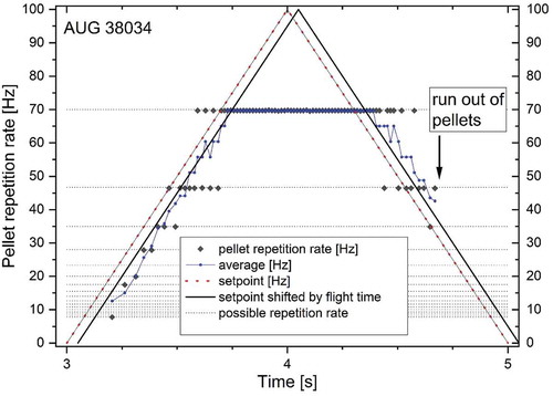
A series of technical tests were carried out in advance in order to make sure the PLC code and the interfaces were working well. With this assured, a first plasma shot was executed. The underlying plasma scenario is known as robust, as this is to check the controller capability in a first step in feedforward mode. The pellet repetition rate is ramped up from 0 to 100 Hz and then back to 0. The maximum possible pellet repetition rate is set to 70 Hz, hence a plateau at 70 Hz is observed, as the controller does not exceed the 100% limit, even if it was technically possible (not in this case).
The new system executed this recipe quite well, using available pellet launching slots as soon as they were requested. The average value of the pellet repetition rate follows the set point ramp well even in the last part, jumping between using every second and every third launching slot. Despite this big step, the ramp was reproduced quite well.
The maximum pellet repetition rate is set by the operator to 70 Hz, every second turn (centrifuge is turning at 140 Hz). The algorithm ignores requests higher than this value. The ramp down stops at ~4.7 s as the reservoir is running out of pellets. The pellet performance was very good in this case, 94% of the requested pellets did arrive on the plasma.
The application of the new controller for delivering a smooth pellet rate ramp into a plasma is shown in . As typically used for this kind of actuator tests, a plasma scenario was employed that has been found to be very robust for high pellet particle fluxes while showing reliable and reproducible performance. Moreover, testing different actuator features in virtually identical plasmas favors comparative analyses. In particular, how much surplus radiation is caused by the pellet-induced density increase in comparison to the extra radiation caused by small amounts of xenon admixed during pellet production was investigated. A more detailed description of the setup, the configuration of the tokamak and plasma, the pellet injection trajectory inside the torus, and essential diagnostics can be found in CitationRef. 8, which reports results from investigations exploring the potential of xenon-doped pellets for radiator control.
Fig. 6. Application of a smooth rate ramp during a pellet train injected into a plasma discharge. The gradual increase of pellet particle flux creates an increasingly peaked density profile at a density level far beyond the Greenwald density. Increasing density alters the ELM behavior and enforces higher radiative losses. Only a mild reduction of the energy confinement is observed until strong mode activity sets in. At about 3.35 s, a short transient impurity event takes place. For DCS request and pellet system answer,
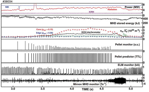
The target discharge shown in is characterized by the following parameters: plasma current IP = 0.8 MA, toroidal magnetic field Bt = 2.48 T, edge safety factor q95 = 5.2, plasma volume Vp = 12.5 m3, elongation κ = 1.72, and upper and lower triangularities δu = 0.12 and δl = 0.45, respectively. H-Mode conditions were established and maintained by steady auxiliary heating comprising neutral beam injection with PNI = 7.3 MW and ion cyclotron resonance heating at 36.5 MHz with PIC = 1.5 MW, adding up with the Ohmic heating to total heating power Ptot = 9.5 MW. The requested pellet actuation can be seen best from the pellet predictor, a transistor-transistor logic control signal communicated to the DCS in order to announce a pellet arrival at the plasma boundary in 3 ms. The pellet monitor signal, indicating positive arrival of a sound pellet in the plasma, is obtained from diagnostics recording the intense radiation caused by the pellet ablation inside the hot plasma. When comparing both signals it becomes obvious that a few requested pellets did not arrive. While 84 pellets had been announced, 75 got delivered. This results in an efficiency of 0.94 and hence reflects the typical system performance.Citation9 The pellet train stops at 4.67 s as the system realized the pellet reservoir was exhausted. Now, despite the still ongoing request by the DCS, no more pellets can be launched and hence no more pellet arrival is announced (see ). With the pellet rate and hence the pellet-born particle flux increasing, the core plasma density rises as well. The observed nonlinear correlation—a linear increase of the flux results in a super linear increase of the core density—is attributed to a longer pellet particle sustainment time in the high-density regime ().
Fig. 7. Plasma discharge in feedforward mode applying a set point ramp (red). Indicated are the pellet repetition rate and the averaged value. All time points are connected to pellet arrival at the plasma, hence the set point ramp is shifted by the pellet flight time. The possible pellet repetition rates are indicated as horizontal lines. The average pellet repetition rate follows well the set point ramp. DCS requests above 70 Hz are ignored, and the system operates at the maximum repetition rate. At 4.7 s, the system runs out of pellets
Around 4.0 s during the maximum flux phase, the line-averaged density peaks at a value of about 1.8 × 10²⁰ m−3, corresponding to a Greenwald fraction fGw of about 1.8. Local measurements from the Thomson Scattering system provide proof a strong density peaking is taking place, the core density transiently reaching a remarkable fGw of 3.5. While the plasma particle inventory increases, radiative losses mainly attributed to Bremsstrahlung increase, too, yet at a moderate level still bearable for the ample heating power being provided. At 3.35 s, a short impurity event, likely a tiny wall flake entering the plasma, results in a transient radiation flash and an according loss of plasma energy. This perturbation, however, by no means derogates this test. With increasing density and radiation, a moderate reduction in the plasma energy content also evolves. Usually, the reduction quickly recovers immediately once the density returns to the initial value after termination of the pellet train.Citation10 However, here this recovery is hindered by strong magnetohydrodynamic (MHD) activity. The MHD activity is mainly caused by a (m = 2,n = 1) tearing mode with its cold (2,1) island flattening the current profile in the center. Once the mode has decayed, the plasma recovers and returns safely to almost its condition prior to the pellet actuation forcing it transiently far beyond limitations not exceedable by simple gas puffing. Therefore, this result clearly demonstrates the potential of the pellet core fueling actuator for gaining access to the high-density regime regarded essential for a future fusion reactor.
V. SUMMARY
A novel scheme for pellet particle flux control is established, eliminating the shortcomings of the previous setup on ASDEX Upgrade. The focus was on opening a way toward the development of fueling systems for future fusion devices like JT-60SA and EU-DEMO. These systems may need to combine several pellet sources, e.g., for ELM pacing as well as for core fueling. With regard to the plasma perturbation caused by pellet injection, a small pellet size seems to be more favorable. On the other hand, in order to fulfil the fueling task, the required particle flux has to be provided. The speed for a stable extrusion of the cryogenic hydrogen in the pellet source is limited. Taking this as boundary condition, the particle throughput of one single pellet source depends on the cross section of the pellet. Thus, for each pellet size, there is a maximum particle throughput per pellet source. This will create the requirement to combine several pellet sources for fueling purposes to be synchronized on one clock. The presented control scheme will be suitable to meet these requirements and provide the flexibility to be integrated in the EU-DEMO plasma control system.
The next step in our activities will be to integrate this system into plasma core density control during plasma experiments on ASDEX Upgrade in feedback mode.
Acknowledgments
The authors would like to express their gratefulness to Thomas Pirsch and Jörg Lösecke for their emphasis on implementing this task and the excellent work they have done as well as the workshop team.
This work has been carried out within the framework of the EUROfusion Consortium and has received funding from the Euratom research and training programme 2014–2018 and 2019–2020 under grant agreement number 633053. The views and opinions expressed herein do not necessarily reflect those of the European Commission.
Raw data were generated at the ASDEX Upgrade facility. Derived data supporting the findings of this study are available from the corresponding author upon reasonable request.
References
- P. T. LANG et al., “Considerations on the DEMO Pellet Fuelling System,” Fusion Eng. Des., 96, 123 (2015); https://doi.org/10.1016/j.fusengdes.2015.04.014.
- T. C. BLANKEN et al., “Model-Based Real-Time Plasma Electron Density Profile Estimation and Control on ASDEX Upgrade and TCV,” Fusion Eng. Des., 147, 111211 (Oct. 2019); https://doi.org/10.1016/j.fusengdes.2019.05.030.
- B. PLOECKL and P. T. LANG, “The Enhanced ASDEX Upgrade Pellet Centrifuge Launcher,” Rev. Sci. Instr., 84, 103509 (2013); https://doi.org/10.1063/1.4824429.
- P. T. LANG et al., “Optimizing the EU-DEMO Pellet Fuelling Scheme,” Fusion Eng. Des., 156, 111591 (2020); https://doi.org/10.1016/j.fusengdes.2020.111591.
- B. PLOECKL et al., “Comparison of Different Pellet Injection Systems for ELM Pacing,” Fusion Eng. Des., 86, 6–8, 1022 (Oct. 2011); https://doi.org/10.1016/j.fusengdes.2011.02.007.
- H. INOSE, Y. YASUDA, and J. MURAKAMI, “A Telemetering System by Code Manipulation—Delta-Sigma-Modulation,” IRE Trans. Space Electron. Telem., SET-8, 204 (1962); https://doi.org/10.1109/IRET-SET.1962.5008839.
- P. T. LANG et al., “Developing Fuel Sources for a Steady-State Multi-Purpose Pellet Launching Systems,” Fusion Eng. Des., 166, 112273 (2021); https://doi.org/10.1016/j.fusengdes.2021.112273.
- P. T. LANG et al., “Targeting a Versatile Actuator for EU-DEMO: Xenon Doping of Fueling Pellets,” Fusion Sci. Technol., 77, 1, 42 (2021); https://doi.org/10.1080/15361055.2020.1842713.
- B. PLOECKL et al., “Advanced ASDEX Upgrade Pellet Guiding System Design,” Rev. Sci. Instrum., 91, 8, 083502 (Aug. 2020); https://doi.org/10.1063/5.0012145.
- P. T. LANG et al., “Feedback Controlled, Reactor Relevant, High-Density, High-Confinement Scenarios at ASDEX Upgrade,” Nucl. Fusion, 58, 3, 036001 (2018); https://doi.org/10.1088/1741-4326/aaa339.