
 ?Mathematical formulae have been encoded as MathML and are displayed in this HTML version using MathJax in order to improve their display. Uncheck the box to turn MathJax off. This feature requires Javascript. Click on a formula to zoom.
Abstract
Laser powder bed fusion (L-PBF) of Glenn Research Copper 42 or 84 (GRCop-42 or GRCop-84) produces a Cr2Nb precipitation-hardened high-conductivity copper alloy with tensile strength superior to other competing copper alloys. Precipitate diameters within GRCop-42 gas-atomized powder increase with powder diameter due to slower cooling rates, however, unlike GRCop-84, no threshold diameter above which extensive precipitate agglomerations form was observed in GRCop-42. Large Cr2Nb crystals were observed in GRCop-42 powder particles, implying formation within the crucible melt. A consistent precipitate volume of ~7% over a range of powder particle diameters indicated a consistent atomization process. Occasional voids were observed in GRCop-42 powder. Precipitate size was refined in L-PBF GRCop-42 to a greater extent than in GRCop-84, improving Orowan strengthening, however, this benefit was lost after heat treatment due to greater coarsening of precipitates. Precipitates in GRCop-42 accumulated on grain boundaries during heat treatment to a greater extent than in GRCop-84.
I. INTRODUCTION
The Cu-Cr-Nb alloysCitation1 include Glenn Research Copper 84 (GRCop-84), 8 at. % Cr, 4 at. % Nb, balance Cu (CitationRef. 2), and Glenn Research Copper 42 (GRCop-42) (CitationRefs. 3, Citation4, Citation5, and Citation6), 4 at. % Cr, 2 at. % Nb, balance Cu. Niobium chromideCitation7 (Cr2Nb) precipitation-hardened alloys have excellent additive manufacturing (AM) properties using laser-powder bed fusionCitation8–10 (L-PBF), resulting in high strength.Citation11 In addition, the Cr2Nb precipitate resists coarsening at high temperatures, allowing for use in rocket engine combustion chambers and fusion reactor components.Citation12,Citation13 The L-PBF of GRCop-84/42 is a key enabling technology for a high-field-side, lower-hybrid-current-drive radio-frequency launcher for the DIII-D tokamak,Citation14–17 where high-temperature bakeouts and disruption loads prevent the use of oxygen-free copper (OFC) due to annealing.
The L-PBF GRCop-84 has a thermal conductivity of 260 W/m∙K3 to 300 W/m∙K4 (75% of OFC), a resistivity of 2.5 µΩ∙cm (CitationRef. 18) (140% of the resistivity of OFC), a yield strength of 470 MPa, and an ultimate tensile strength (UTS) of 710 MPa in as-printed condition.Citation8 The L-PBF GRCop-42 has a thermal conductivity of 270 to 350 W/m∙K (90% of OFC), a yield strength of 300 MPa, and a UTS of 490 MPa in as-printed condition, reducing to 200 MPa and a UTS of 350 MPa in hot isostatic–pressed (HIPed) condition.Citation1,Citation3,Citation5,Citation6
Although there was a modest decrease in the low-temperature tensile strength of GRCop-42, the tensile strength above 600°C was almost equivalent to GRCop-84, and the enhanced thermal conductivity is beneficial in propulsion applications.Citation1,Citation3 The improved thermal conductivity and favorable gas-atomization properties of GRCop-42 compared to GRCop-84 has led a shift to GRCop-42 for the production of additive manufactured rocket engines.Citation1,Citation3 As the dominant market for GRCop alloy powders is rocket engine manufacture, this has led to a decreased availability of GRCop-84 AM capability as production migrates to the GRCop-42 alloy. Analysis of precipitates in GRCop-42 and GRCop-84 gas-atomized powders will help predict precipitate formation behavior within these alloys, as well as future copper alloys under development using niobium-free laves-phase precipitate hardening to reduce waste disposal issues due to neutron activation of niobium.Citation19–21
In this paper, the precipitate size distributions within gas-atomized GRCop-42 powder particles are compared across particle diameter and to L-PBF material. Size distributions in L-PBF and gas-atomized GRCop-42 are compared to prior studies of GRCop-84 powder and L-PBF material,Citation22 where the L-PBF process has been shown to refine the precipitate size compared to the gas-atomized powder. Differences in precipitate sizes, structures, and distributions are analyzed between these two alloys. As in GRCop-84, precipitate sizes in gas-atomized GRCop-42 powder particles are much larger than in as-printed GRCop-42 material with no heat treatment, indicating that precipitates are either melted and reprecipitated out of the solution as the melt pool cools or broken up during the L-PBF process. Tensile strength in the L-PBF GRCop-42 was therefore unlikely to be affected by the precipitate size within the gas-atomized powder. Differences in Orowan strengthening between GRCop-84 and GRCop-42 are compared prior to and following heat treatment. Orowan strengthening explains the increased tensile strength in GRCop-42 processed by L-PBF due to reduction in precipitate size, compared to HIPing or extrusion from powder, which maintains the precipitate sizes present within the gas-atomized powder stock.
II. GAS ATOMIZATION COOLING RATE
Gas atomization provides the rapid cooling rate required to maintain submicron precipitate sizes of GRCop 84 and 42 (CitationRef. 12) to prevent the formation of large Cr2Nb chunks that otherwise grow up to 1 cm during casting due to slow cooling.Citation23,Citation24 The precipitate distribution pins grain boundary growth at high temperatures with larger precipitates and provides dislocation obstacles with small precipitates resulting in Hall-PetchCitation25 and Orowan strengthening.Citation23 The low solubility of the Cr2Nb in the copper matrix resists coarsening at high temperatures, but requires a high crucible melting temperature to ensure full solubility prior to gas atomization. The Cr2Nb precipitates agglomerate or coarsen after forming within the molten copper droplet prior to the solidification of the copper matrix,Citation24 with a size distribution controlled by the cooling rate.
During gas atomization, contact with a supersonic flow of argon surrounding an atomization nozzleCitation26 breaks up the aspirated Cu-Cr-Nb solution into spherical droplets that solidify in flight into powder particles. Droplet cooling has been modeled numerically by simulating heat transfer from the droplet during gas atomization, and empirically by the measurement of the internal microstructure controlled by the cooling rate. Most numerical models estimate droplet cooling in the fully liquid and solid states by Fourier’s law of heat conduction,Citation27,Citation28 including radiation cooling,Citation29 given by
where
| ρ | = | = metal density |
| C | = | = specific heat |
| d | = | = powder particle diameter |
| Tp | = | = droplet temperature |
| Tgas | = | = gas temperature |
| Tw | = | = wall temperatures |
| ε | = | = emissivity of an atomized particle |
| σ | = | = Stefan-Boltzmann constant |
| h | = | = heat transfer coefficient given by the Ranz-Marshall correlation in EquationEq. (2) |
where Re is the Reynolds number, Pr is the Prandtl number, and k is the thermal conductivity of the surrounding gas. The cooling rate was therefore proportional to in this model.Citation26 Radiation cooling was two orders of magnitude less than convection cooling for the Al4.5Cu alloy droplets less than 100 µm in diameter for a 921-K liquidus temperature,Citation30 and this term is typically neglected except in cases of high atomization temperatures; EquationEq. (1)
(1)
(1) then reduces to EquationEq. (3)
(3)
(3) for convective dominated cooling:
Numerical models of droplet coolingCitation31,Citation32 were compared to experimental values estimated by dendrite arm spacing.Citation33,Citation34 The typical cooling rates of gas-atomized powder were quoted between 10−4 to 10−6 K/s for 5- to 60-µm droplet diametersCitation30 or 104 to 107 K/s (CitationRef. 32) for aluminum alloy powders. Empirical models of the 6Cu wt.% Sn alloy (Cu6Sn) atomized with close-coupled and free-fall atomization in argon gas had estimated cooling rates of 1 × 10⁴ to 5 × 10⁴ K/s for 5- to 50-µm-diameter powder granules,Citation33 which was confirmed by dendrite arm spacing measurements across several different alloys.Citation35 Gas atomization conditions, including gas temperature, gas-to-melt ratio, and atomization pressure, were determined to only have a modest effect on the cooling rate between different atomization setupsCitation33; this relative parameter insensitivity implied that gas-atomized powders of the same alloy from different manufacturers will have similar cooling rates. Cooling rates of 106 K/s attained in the chill block melt spinning (CBMS) of GRCop-84 were insufficient to suppress Cr2Nb precipitate formation and resulted in an average diameter in the 5- to 9.5-nm range.Citation7 Cooling rates in gas-atomized powders were less than those produced in CBMS; therefore, the precipitate diameters were expected to be larger.
III. GAS ATOMIZATION OF GRCop-42 AND GRCop-82
The GRCop-84 powder was produced by ATI Powder Metals,Citation36 while the GRCop-42 powder was produced by Powder Alloy Corporation.Citation37 Crucible melting temperatures and gas atomization parameters were considered proprietary and their processes were not shared; the GRCop-84 required a 150°C to 200°C higher crucible melting temperature than the GRCop-42 (CitationRef. 38). The solidus of the GRCop-84/42 was determined by the solidus of the copper matrix at 1084°C, while the liquidus was determined by the solubility limit of Nb and Cr in liquid copper; the higher fraction of Cr and Nb in GRCop-84, shown in , required a higher temperature for complete dissolution. The GRCop-84 had a liquidus between 1735°C and 1800°C (CitationRef. 39) and required a crucible melting temperature of 1750°C (CitationRefs. 23 and Citation40) for gas atomization. The Cr2Nb at 8 at. % Cr, 4 at. % Nb was stable in liquid Cu between 1704°C and 1733°C (CitationRef. 41). The pure Cr2Nb laves phase melts at 1773°C (CitationRefs. 42 and Citation43). During production of the GRCop melts, alumina crucibles were painted with yttria oxide to prevent niobium fluxing and attack, which occurs above 50 at. % Nb (CitationRef. 40).
TABLE I Atomic and Mass Fractions for GRCop-84 and GRCop-42
Gas-atomized powder is characterized by a cumulative distribution function of the percentage of powder by mass greater than a specified diameter and a micrograph of powder particles, shown in for GRCop-84 and in for GRCop-42. The GRCop-42 powder particles had larger average diameters than the GRCop-84 powder particles. A 50-μm-diameter GRCop-42 powder particle sectioned at several heights showed uniform precipitate characteristics throughout the powder particle, as seen in . This implies negligible radial dependence on precipitate formation. Consistent precipitate structures throughout powder particles of different diameters sectioned near the midplane, shown in , support this observation. This characteristic implies that a gas-atomized particle is effectively an isothermal volume that cools at a relatively uniform internal temperature.
Fig. 1. (a) CDF by mass of GRCop-84 and (b) GRCop-42 powder and scanning electron microscopy image of powder particles.
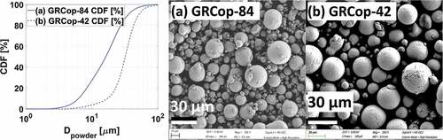
Fig. 2. Serially FIB-milled 50.2-μm-diameter gas-atomized GRCop-42 powder particle sectioned at height h showing uniformity of precipitate size over several sectioning heights.
Fig. 3. FIB-sectioned GRCop-42 gas-atomized powder particles between 5 and 60 μm in diameter, and as-printed and 900°C 5-h heat-treated GRCop-42 material. Slower cooling of larger-diameter particles resulted in large precipitates, while the L-PBF process refined precipitate size. Note the difference in the scale bars.
IV. PRECIPITATE ANALYSIS OF GRCop-42 AND GRCop-82 PARTICLES
Gas-atomized GRCop-42 powder particles between 5.1 and 60.3 μm in diameter were cut in half near the diameter with a focused ion beam (FIB) mill to analyze precipitates within each powder particle. Sampling was limited to 21 powder particles due to the time constraints of FIB milling. A minimum diameter of 5 μm was selected to provide a sufficient ensemble of precipitates for statistical analysis. Powder particle diameters were chosen over a similar range and similar to diameters of those chosen in prior studies of GRCop-84 gas atomized powder.Citation21
Precipitates within a FIB section of a powder particle, shown in , were counted by area. Size distributions of the equivalent circular diameter of a spherical precipitate measured from area A contained within the cross section of a precipitate in , are plotted in and compared to GRCop-42 as printed and heat treated at 900°C for 5 h. The precipitate volume fraction was approximated from the ratio of the surface area of the precipitates to the total area within an enclosing convex hull.Citation21
Fig. 4. Area fraction of the Cr2Nb precipitates within gas-atomized GRCop-42 particles (ACr2Nb/AΣ) compared to the quoted value of 7% (dashed black line). Box plot of precipitate sizes within gas-atomized GRCop-42 powder particles (DCr2Nb). Whiskers extend at most up to q3 + 1.5 × (q3 – q1) or down to q1 – 1.5 × (q3 – q1); particle sizes outside the whiskers are marked as outliers. Mean “O” and Mode “X” of precipitate size include outliers. Average precipitate sizes in the as-printed GRCop-42 are indicated by a blue line with ±1σ error bars (dashed blue).
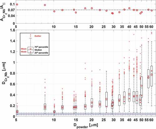
Precipitates in GRCop-84 occupy 14% by volume.Citation2 The equivalent precipitate area/volume in GRCop-42 would be 7%, as the precipitate atomic fraction is half that of GRCop-84. The measured area/volume of Cr2Nb precipitates in the GRCop-42 powder particles was 6.9% (σ = 1.25%), as shown in the top of , while for GRCop-84, the area/volume was 16.2% (σ = 2.74%) (improved image processing produced slightly different values from CitationRef. 21). The precipitate volume fraction was uniform across the set of particles, implying a consistent gas atomization process.
Gas-atomized GRCop-42 powder particles exhibit an increase in average precipitate size above a ~50-μm threshold in diameter, as shown in the bottom of . Larger precipitates due to coarsening were attributed to a slower cooling rate during gas atomization, inversely proportional to the square of the powder particle diameter.Citation26 Agglomerations of precipitates in the GRCop-42 were infrequent across the range of diameters. Precipitate distributions in the GRCop-42 exhibited a slightly positive skew. As in the GRCop-84 (CitationRef. 21), L-PBF was shown to refine the precipitate diameter in GRCop-42.
Similar GRCop-84 and GRCop-42 powder particle diameters resulted in different precipitate distributions and morphologies, which is attributed to differing cooling rates and precipitate volume. The precipitate size distributions of GRCop-42 and GRCop-84 are shown overlayed in as mean and median values with ±1σ error bars. As the powder particle diameter increased, the GRCop-84 crossed a diameter threshold at ~17 μm, above whichCitation21 large agglomerations of precipitates formed within the powder particle, as shown for the GRCop-84 powder particles in . However, in GRCop-42, these large agglomerations of precipitates did not form and no diameter threshold was found for agglomerations in the range of the evaluated diameters up to 60 μm. A sharp increase in the precipitate diameter in the GRCop-42 does occur above a ~50-μm threshold, however these precipitates were of the coarsened variety and not agglomerations of precipitates. Large crystalline Cr2Nb granules were found in several of the GRCop-42 powder particles, as shown in . These crystals had sharp, straight edges and angular corners and were morphologically distinct from the rounded precipitates in the GRCop-42 gas-atomized particles or the agglomerations of precipitates in the GRCop-84 gas-atomized particles, implying that these crystals formed in the crucible melt rather than during the atomization process.
Fig. 5. Comparison of precipitate sizes in the GRCop-42 and GRCop-84 (CitationRef. 21) powders. Mean precipitate sizes are indicated with a circle with ±1σ error bars, while median values are indicated with a horizontal dash. Median values of the Cr2Nb precipitate diameter within the GRCop-42 powder particles were approximately equal to the mean value, while the median precipitate diameter in the GRCop-84 powder was often noticeably less than the mean.
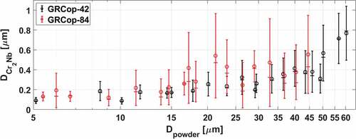
Fig. 6. Structures of the Cr2Nb precipitates in the GRCop-84 (CitationRef .21) and GRCop-42 gas-atomized powders. Precipitate agglomerations form in the GRCop-84 above a threshold in diameter; no equivalent effect was observed in the GRCop-42.
Fig. 7. Structures of the Cr2Nb precipitates in the GRCop-84 (CitationRef. 21) and GRCop-42 gas-atomized powders. The GRCop-84 powder granules greater than 17 µm in diameter show agglomeration of precipitates while the GRCop-42 powders show a gradual coarsening with increasing diameter. The GRCop-42 powders show chunks of Cr2Nb with sharp edges and voids within the copper matrix in several granules over a range of diameters.
In contrast to many precipitation-hardened copper alloys where precipitates are formed from a solid solution during postproduction heat treatment, the relative insolubility of Nb and Cr in liquid copper results in Cr2Nb precipitating from the molten copper solutionCitation11 prior to the solidification of the copper matrix. The solubility limit for Cr2Nb (CitationRef. 1) therefore occurred at a higher temperature for the GRCop-84 than for the GRCop-42, requiring a ~200°C higher crucible melting temperatureCitation37 to ensure full solubility. During the atomization process, the temperature difference between the beginning of precipitate formation within the liquid copper and the solidification of the copper matrix, and therefore the cooling time, was greater for the GRCop-84 than it was for the GRCop-42.
Additionally, the latent heat of fusion of the Cr2Nb precipitating within the copper droplet released heat that slowed the cooling process; therefore, the greater fraction of Cr2Nb precipitating in the GRCop-84 would slow droplet cooling compared to the GRCop-42, thus increasing the time for precipitates to agglomerate. The greater area/volume fraction of Cr2Nb in the GRCop-84 (~14% in GRCop-84, while ~7% in GRCop-42) likely contributed to a larger prevalence of agglomerations as the precipitates were statistically more likely to touch.
The GRCop-42 gas-atomized powder particles occasionally had small internal voids, observed in the 17.8-, 29.2-, 43.5-, 50.2-, 56.8-, and 60.3-μm-diameter particles, as shown in . While voids in the powder particles were shown to contribute to voids in the L-PBF material, voids observed in the L-PBF GRCop-42, shown in , were typical of the voids in the L-PBF GRCop-42 during computed tomography analysisCitation6 and were attributed to the AM process. These voids are not anticipated to greatly contribute to voids in the final L-PBF material.
Fig. 8. Comparison of precipitates in the as-printed and 900°C 5-h heat-treated GRCop-84 (CitationRef. 21) and GRCop-42 material. Precipitates are black while the copper matrix is gray. Different shades of gray in the copper matrix indicate different grain orientations. Vertical lines are artifacts of the FIB milling process.

V. PRECIPITATE SIZE IN L-PBF ADDITIVE MANUFACTURED GRCop-84 AND GRCop-42
During L-PBF, components are additively manufactured under an inert atmosphere with a scanning laser that melts a cross-sectional layer of gas-atomized powder onto the underlying layers. An infill pattern scanned in a raster pattern consolidates the interior solid volume of the part, while a contour spanning one to two line widths scanned along the outer perimeter of the cross section improves the surface finish. The L-PBF GRCop analyzed in this paper was taken from the infill volume of the sample.
The L-PBF of GRCop-84 at Quadrus Corp.Citation44 used a Concept Laser M2 with a checker-box-hatch-pattern infill rotated and translated between layers, while the L-PBF of GRCop-42 at Additive Manufacturing & Engineering, Inc. (CitationRef. 45) used an EOS M400-1 with a unidirectional infill pattern rotated between layers. Exact laser power and scanning speed parameters for the GRCop-42 are proprietary and were not specified by the manufacturer. The GRCop-42 parameters used were derived from published National Aeronautical and Space Administration parameters of 270 W power, 1025 mm/s scan speed, and 0.030 mm layer thickness, but modified for the 0.040-mm layer thickness used in the samples.Citation46 The L-PBF parameters for GRCop-84 and GRCop-42 are listed in .
TABLE II L-PBF Parameters for GRCop-84 and GRCop-42
Precipitate distributions in the L-PBF GRCop-84 and GRCop-42 in the as-printed condition and following a 900°C 5-h heat treatment are shown in . The GRCop-42 as-printed cross section () shows an internal void attributed to the L-PBF process; voids in the GRCop-42 (CitationRef. 6) were more common than in the GRCop-84 due to the higher conductivity and reduced coupling to fiber lasers.Citation47–49 The precipitate size in the L-PBF GRCop-42 was refined similar to the effects in GRCop-84 (CitationRef. 21), implying a similar increase in tensile strength through the Orowan mechanismCitation50 compared to material extruded or HIPed from powder, where powder precipitate sizes were maintained in the condensed material.
A small distribution of coarsened precipitates was observed in the as-printed GRCop-42 (), an effect not observed in the GRCop-84. The area within a 1- to 2-µm radius of the coarsened precipitates (center column in ) was devoid of the fine precipitates present in the surrounding material, implying that these coarsened precipitates formed during the L-PBF process and not from the large chunks of Cr2Nb occasionally present in the GRCop-42 gas-atomized powder shown in , where the large granules of Cr2Nb were surrounded by a uniform distribution of fine Cr2Nb precipitates distributed evenly throughout the powder particles.
Precipitates were evenly distributed throughout the as-printed L-PBF GRCop-84 and GRCop-42 with no tendency to accumulate at grain boundaries; similar behavior was observed in the gas-atomized powder for both alloys. Precipitates for both the as-printed alloys show little skew in precipitate size distribution (see ); the GRCop-84 had a 90-nm average diameter, while the GRCop-42 had a 45.5-nm average diameter (see ). Following a 900°C 5-h heat treatment, the coarsening of precipitates was observed in both the GRCop-84 and GRCop-42; the GRCop-84 had a 143-nm average diameter, while the GRCop-42 had a 158-nm average diameter, both with a strong positive skew due to coarsened precipitates. While the GRCop-84 exhibited a more random distribution of coarsened precipitates throughout the copper matrix, coarsened precipitates accumulated along grain boundaries in the GRCop-42 to a much greater extent (see center column of ), while smaller precipitates remained within the copper grain. Precipitates have been shown to accumulate along the grain boundaries in GRCop-84 in prior experiments,Citation8 the effect of which is shown in . This implies that this effect may occur to a greater extent in the GRCop-42.
TABLE III Precipitate Size Statistics for GRCop-84 and GRCop-42
Fig. 9. Comparison of the Cr2Nb precipitate size distributions in (a) and (b) GRCop-84 and (c) and (d) GRCop-42 L-PBF material in the (a) and (c) as-printed condition and (b) and (d) following a 900°C 5-h heat treatment. Whiskers in the box plots extend at most up to q3 + 1.5 × (q3 – q1) or down to q1 – 1.5 × (q3 – q1); particle sizes outside the whiskers are marked as outliers (+), while a notch indicates 96% CI of median. Mean (o) of precipitate size includes outliers.
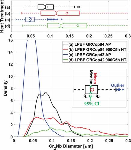
Precipitate size distributions in the GRCop-84 and GRCop-42 are plotted in . Mean precipitate diameters in the as-printed GRCop-42 were half those in the GRCop-84; however, following a 900°C 5-h heat treatment, precipitates in the GRCop-42 coarsened to a slightly larger diameter than those in the GRCop-84. This could be attributed to a larger fraction of smaller precipitates in the heat-treated GRCop-84 that coarsened out of residual Cr and Nb in the solid solution, or a larger fraction of precipitates that were previously below the resolution of the electron microscope that coarsened during heat treatment. Precipitates in the GRCop-84 occupied 16.2% volume in the gas-atomized powder, 14.1% in the as-printed material, and 15% in the heat-treated material, while in the GRCop-42, precipitates occupied 6.9% volume in the gas-atomized powder, 7.1% in the as-printed material, and 8% in the heat-treated material, implying further precipitation of Cr2Nb with heat treatment as has been observed in prior studies.Citation23
Orowan strengthening Δσ representing the increase in strength of the bulk alloyCitation1 is given by EquationEq. (4):(4)
(4)
where
| G | = | = matrix shear modulus |
| b | = | = Burgers vector (0.255 nm for copper) |
| r | = | = average particle radius |
| λLD | = | = linear mean free path of dislocations between the particles approximated by EquationEq. (5) |
Therefore, in terms of volume fraction and particle radius alone, the Orowan strengthening is proportional to EquationEq. (6)(6)
(6) , as all other factors were constant between the two alloys:
Given the known average precipitate diameters and volume fractions shown in and , the ratio of Orowan strengthening between the GRCop-42 and GRCop-84 is given by EquationEq. (7)(7)
(7) in the as-printed condition and EquationEq. (8)
(8)
(8) after a 900°C 5-h heat treatment:
and
The precipitates in both the as-printed and the 900°C 5-h heat-treated L-PBF GRCop-42 therefore provide less strengthening to the copper matrix than those in the GRCop-84. However, accounting for the fact that the GRCop-42 has half the fraction of precipitates as the GRCop-84 to improve thermal conductivity, the smaller refined precipitate diameter produced in the L-PBF process becomes advantageous as the Orowan strengthening was 80% that of the GRCop-84. Much of this advantage was lost after high-temperature heat treatment as the precipitates in the GRCop-42 coarsened to a larger diameter than in the GRCop-84.
VI. SUMMARY
Several differences exist between the precipitate sizes in the gas-atomized GRCop-84 and GRCop-42 powder particles that can be attributed to differences in the cooling process and precipitate fraction. The differences are as follows:
Precipitate size in the GRCop-42 gas-atomized powder increased with powder particle diameter due to a slower cooling rate, similar to the GRCop-84.
Unlike the GRCop-84, where precipitate agglomeration occurs above a diameter threshold, no threshold for large agglomerations of precipitates existed for the GRCop-42 powder particles.
A sharp increase in precipitate diameter occurred above 50 μm in the GRCop-42 powder particles; these precipitates were of the coarsened type, but not agglomerations.
Occasional large crystals of Cr2Nb existed in the GRCop-42 powder, likely forming in the crucible melt, not the atomization process. These crystals were not found in the GRCop-84 powder.
Small voids existed in the GRCop-42 powder.
The average precipitate diameter in the as-printed L-PBF GRCop-42 was half that of the GRCop-84.
After a 900°C 5-h heat treatment, precipitate diameter in the GRCop-42 was greater than in the GRCop-84.
Precipitates in the heat-treated GRCop-42 accumulated along grain boundaries to a greater extent than in the GRCop-84.
Precipitates in the as-printed GRCop-42 were more effective in providing Orowan strengthening than in the GRCop-84 per atomic fraction in the alloy; this advantage was lost after heat treatment.
VII. CONCLUSION
Differences exist in the precipitate size distribution and morphology in the GRCop-84 and GRCop-42 gas-atomized powders. The GRCop-42 exhibited an increase in precipitate size with increasing gas-atomized particle diameter due to reduced cooling rates; unlike the GRCop-84, no diameter threshold was found above which large agglomerations of Cr2Nb formed. This was attributed to the greater atomic fraction of Cr2Nb within the GRCop-84, the precipitation of which released heat into the molten copper, slowing the cooling process of the gas-atomized droplets. This effect, in conjunction with the higher required crucible melting temperature, led to a greater time between precipitate formation and solidification of the copper matrix, extending the period in which precipitates may agglomerate.
A threshold above 50 µm exists in the GRCop-42 where precipitate size sharply increases, however, these precipitates were of the coarsened, not agglomerated variety. These effects are neither a detriment nor benefit to either the GRCop-84 or GRCop-42 when the powder is to be consolidated with L-PBF, as the L-PBF process has been shown to refine the precipitate size in both alloys by either melting and subsequently reprecipitating Cr2Nb as the melt pool rapidly cools, or by breaking up precipitates in the turbulent melt.
Increased Orowan strengthening due to the reduction in precipitate size explained the higher tensile strength in L-PBF GRCop alloys when compared to GRCop HIPed or extruded from powder, where powder precipitate sizes are maintained in the condensed material. This implies precipitate size within the powder does not affect size, and thus the tensile strength of the L-PBF-printed material. GRCop-42 HIPed or extruded from powder will be stronger if powder particles under 50 μm in diameter are used, as precipitates that agglomerated or coarsened at high temperature observed during the 900°C 5-h heat treatment of L-PBF material remained smaller than precipitates observed in most powder particles. This margin of diameter was greater than the 17-μm threshold found in the GRCop-84, allowing for better utilization of the gas-atomized powder if consolidation through HIPing or extrusion is to be used.
In the L-PBF material, precipitate size in the GRCop-42 was half that of the GRCop-84, leading to better utilization of precipitates for Orowan strengthening. However, due to the susceptibility to coarsening, this advantage was lost after heat treatment or the temperatures required for HIPing. Heat treatment temperatures should be limited to prevent precipitate coarsening. During heat treatment, coarsened precipitates in the GRCop-42 accumulated on the grain boundaries to a greater extent than those in the GRCop-84.
Author Contributions
A.H. Seltzman: conceptualization, data curation, formal analysis, investigation, methodology, software, validation, visualization, writing – original draft, writing – review & editing; S.J. Wukitch: funding acquisition, project administration, resources, supervision.
Acknowledgments
This work was supported by the U.S. Department of Energy (DOE), Office of Science, Office of Fusion Energy Sciences, using User Facility DIII-D under award no. DE-FC02-04ER54698, and by the DOE Advanced Research Projects Agency-Energy using Bridge-12 funding through the Prime Cooperative Agreement award number DE-AR0001380. This work made use of the MRSEC Shared Experimental Facilities at the Massachusetts Institute of Technology, which is supported by the National Science Foundation under award number DMR-14-19807.
Disclosure Statement
No potential conflict of interest was reported by the authors.
Data Availability
Data, images, and code required to recreate results in this paper are available online in a digital format at https://doi.org/10.17632/sn5wczn73j.1.
References
- R. P. MINNECI et al., “Copper-Based Alloys for Structural High-Heat-Flux Applications: A Review of Development, Properties, and Performance of Cu-Rich Cu-Cr-Nb Alloys,” Int. Mater. Rev., 66, 6, 394 (2021); https://doi.org/10.1080/09506608.2020.1821485.
- D. L. ELLIS, “GRCop-84: A high-temperature Copper Alloy for high-geat-flux Applications,” NASA/TM 2005-213566, National Aeronautics and Space Administration (2005);https://ntrs.nasa.gov/citations/20050123582.
- P. R. GRADL et al., “GRCop-42 Development and Hot-Fire Testing Using Additive Manufacturing Powder Bed Fusion for Channel-Cooled Combustion Chambers,” presented at the AIAA Propulsion and Energy Forum, p. 4228, August 19–22, 2019, Indianapolis, Indiana ( 2019).
- P. R. GRADL et al., “Progress in Additively Manufactured Copper-Alloy GRCop-84, GRCop-42, and Bimetallic Combustion Chambers for Liquid Rocket Engines,” Proc. 70th Int. Astronautical Congress, Document ID 2019003331 (2019); https://ntrs.nasa.gov/citations/20190033311.
- G. DEMENEGHI et al., “Direct Energy Deposition GRCop-42 Copper Alloy: Characterization and Size Effects,” Mater. Des., 222, 111035 (2022); https://doi.org/10.1016/j.matdes.2022.111035.
- G. DEMENEGHI et al., “Size Effects on Microstructure and Mechanical Properties of Additively Manufactured Copper-Chromium-Niobium Alloy,” Mater. Sci. Eng.A, 820, 141511 (2021); https://doi.org/10.1016/j.msea.2021.141511.
- D. L. ELLIS and G. M. MICHAL, “Formation of Cr and Cr2Nb Precipitates in Rapidly Solidified Cu-Cr-Nb Ribbon,” Ultramicroscopy, 30, 1–2, 210 (1989); https://doi.org/10.1016/0304-3991(89)90189-7.
- C. HAYES et al., “Characterization of Selective Laser Melted GRCop-84,” Proc. 2018 Joint Propulsion Conf., Cincinnati, Ohio, July 9–11, 2018, p. 4624 ( 2018). https://doi.org/10.2514/6.2018-4624
- A. H. SELTZMAN and S. J. WUKITCH, “Resolution and Geometric Limitations in Laser Powder Bed Fusion Additively Manufactured GRCop-84 Structures for a Lower Hybrid Current Drive Launcher,” Fusion Eng. Des., 173, 112847 (2021); https://doi.org/10.1016/j.fusengdes.2021.112847.
- M. B. WILMS and S.-K. RITTINGHAUS, “Laser Additive Manufacturing of Oxide Dispersion-Strengthened Copper-Chromium-Niobium Alloys,” J. Manuf. Mater. Process., 6, 5, 102 (2022); https://doi.org/10.3390/jmmp6050102.
- A. H. SELTZMAN and S. J. WUKITCH, “Fracture Characteristics and Heat Treatment of Laser Powder Bed Fusion Additively Manufactured GRCop-84 Copper,” Mater. Sci. Eng., 827, 141690 (2021); https://doi.org/10.1016/j.msea.2021.141690.
- H. C. de GROH III et al., “Comparison of GRCop-84 to Other Cu Alloys with High Thermal Conductivities,” J. Mater. Eng. Perform., 17, 4, 594 (2008); https://doi.org/10.1007/s11665-007-9175-3.
- H. C. de GROH III et al., Comparison of GRCop-84 to Other High Thermal Conductive Cu Alloys,” NASA/TM-2007-214663, National Aeronautics and Space Administration (2007); https://ntrs.nasa.gov/citations/20070017311.
- A. H. SELTZMAN et al., “A High Field Side Multijunction Launcher with Aperture Impedance Matching for Lower Hybrid Current Drive in DIII-D Advanced Tokamak Plasmas,” Nucl. Fusion, 59, 9, 096003 (2019); https://doi.org/10.1088/1741-4326/ab22c8.
- A. H. SELTZMAN and S. J. WUKITCH, “RF Losses in Selective Laser Melted GRCop-84 Copper Waveguide for an Additively Manufactured Lower Hybrid Current Drive Launcher,” Fusion Eng. Des., 159, 111762 (2020); https://doi.org/10.1016/j.fusengdes.2020.111762.
- A. H. SELTZMAN and S. J. WUKITCH, “Surface Roughness and Finishing Techniques in Selective Laser Melted GRCop-84 Copper for an Additive Manufactured Lower Hybrid Current Drive Launcher,” Fusion Eng. Des., 160, 111801 (2020); https://doi.org/10.1016/j.fusengdes.2020.111801.
- A. H. SELTZMAN and S. J. WUKITCH, “Nuclear Response of Additive Manufactured GRCop-84 Copper for Use in Lower Hybrid Launchers in a Fusion Environment,” Fusion Eng. Des., 159, 111726 (2020); https://doi.org/10.1016/j.fusengdes.2020.111726.
- D. L. ELLIS et al., “Thermophysical Properties of GRCop-84,” NASA/CR-2000-210055, National Aeronautics and Space Administration (2000); https://ntrs.nasa.gov/citations/20000064095.
- G. M. WALLACE et al., “Ultra-Rapid, Physics-Based Development Pathway for Reactor-Relevant RF Antenna Materials.” In IEEE Transactions on Plasma Science (2022); https://doi.org/10.1109/TPS.2022.3171497.
- S. FETTER, E. T. CHENG, and F. M. MANN, “Long-Term Radioactive Waste from Fusion Reactors: Part II,” Fusion Eng. Des., 13, 2, 239 (1990); https://doi.org/10.1016/0920-3796(90)90104-E.
- F. A. HERNÁNDEZ and P. PERESLAVTSEV, “First Principles Review of Options for Tritium Breeder and Neutron Multiplier Materials for Breeding Blankets in Fusion Reactors,” Fusion Eng. Des., 137, 243 (2018); https://doi.org/10.1016/j.fusengdes.2018.09.014.
- A. H. SELTZMAN and S. J. WUKITCH, “Precipitate Size in GRCop-84 Gas Atomized Powder and Laser Powder Bed Fusion Additively Manufactured Material,” Fusion Sci. Technol., 77, 7–8, 641 (2021); https://doi.org/10.1080/15361055.2021.1913030.
- D. L. ELLIS, H. R. GRAY, and M. NATHEL, “Aerospace Structural Materials Handbook Supplement GRCop-84,” Nation Aeronautics and Space Administration (2001);. https://ntrs.nasa.gov/citations/20020070630.
- K. R. ANDERSON et al., “Microstructural Evolution and Thermal Stability of Precipitation-Strengthened Cu-8Cr-4Nb Alloy,” Mater. Sci. Eng., 169, 1–2, 167 (1993); https://doi.org/10.1016/0921-5093(93)90611-H.
- K. R. ANDERSON et al., “High-Performance Dispersion-Strengthened Cu-8 Cr-4 Nb Alloy,” Metall. Mater. Trans. A, 26, 9, 2197 (1995); https://doi.org/10.1007/BF02671235.
- E. J. LAVERNIA and T. S. SRIVATSAN, “The Rapid Solidification Processing of Materials: Science, Principles, Technology, Advances, and Applications,” J. Mater. Sci., 45, 2, 287 (2010); https://doi.org/10.1007/s10853-009-3995-5.
- R. B. BIRD, W. E. STEWART, and E. N. LIGHTFOOT, Transport Phenomena, Wiley, New York (1960); https://doi.org/10.1002/aic.690070245.
- A. ÜNAL, “Production of Rapidly Solidified Aluminum Alloy Powders by Gas Atomisation and Their Applications,” Powder Metall., 33, 1, 53 (1990); https://doi.org/10.1179/pom.1990.33.1.53.
- J. VALLOTON, S. GAWOR, and H. HENEIN, “Modelling of Nucleation in Impulse Atomized Undercooled Droplets,” Comput. Mater. Sci, 144, 176 (2018); https://doi.org/10.1016/j.commatsci.2017.12.004.
- D. GIANOGLIO et al., “On the Cooling Rate-Microstructure Relationship in Molten Metal Gas Atomization,” Metall. Mater. Trans. A, 52, 9, 3750 (2021); https://doi.org/10.1007/s11661-021-06325-2.
- G. PEREZ-de LEON et al., “Gas Atomization of Molten Metal: Part I. Numerical Modeling Conception,” Am. J. Eng. Appl. Sci., 9, 2, 303 (2016); https://doi.org/10.3844/ajeassp.2016.303.322.
- T. M. ABU-LEBDEH et al., “Gas Atomization of Molten Metal: Part II. Applications,” Am. J. Eng. Appl. Sci., 9, 2, 334 (2016); https://doi.org/10.3844/ajeassp.2016.334.349.
- H. SHIWEN, L. YONG, and G. SHENG, “Cooling Rate Calculation of Non-equilibrium Aluminum Alloy Powders Prepared by Gas Atomization,” Rare Metal Mater. Eng., 38, 4, 353 (2009).
- N. CIFTCI et al., “Novel Cooling Rate Correlations in Molten Metal Gas Atomization,” Metall. Mater. Trans. A Phys. Metall. Mater. Sci., 50, 2, 666 (2019); https://doi.org/10.1007/s11663-019-01508-0.
- A. M. MULLIS et al., “Estimation of Cooling Rates During Close-Coupled Gas Atomization Using Secondary Dendrite Arm Spacing Measurement,” Metall. Mater. Trans. A Phys. Metall. Mater. Sci., 44, 4, 992 (2013); https://doi.org/10.1007/s11663-013-9856-2.
- M. SPERBER, Personal Correspondence, ATI Powder Metals (2019).
- R. MEKLUS, Personal Correspondence, Powder Alloy Corporation (2022).
- C. R. MARION, Personal Correspondence, ATI Powder Metals (2022).
- X. J. LIU et al., “Experimental Determination and Thermodynamic Calculation of the Phase Equilibria in the Cu–Cr–Nb and Cu–Cr–Co Systems,” J. Alloys Compd., 478, 1–2, 287 (2009); https://doi.org/10.1016/j.jallcom.2008.11.162.
- D. L. ELLIS and G. M. MICHAL, “Precipitation Strengthened High Strength, High Conductivity Cu-Cr-Nb Alloys Produced by Chill Block Melt Spinning,” NAS 1.26:185144, National Aeronautics and Space Administration (1989); https://ntrs.nasa.gov/citations/19900002537.
- D. L. ELLIS, G. M. MICHAL, and N. W. ORTH, “Production and Processing of Cu-Cr-Nb Alloys,” NAS 1.15:102495, National Aeronautics and Space Administration (1990); https://ntrs.nasa.gov/citations/19900006737.
- M. VENKATRAMAN and J. P. NEUMANN, “The Cr-Nb (Chromium-Niobium) System,” Bull. Alloy Phase Diagrams, 7, 5, 462 (1986); https://doi.org/10.1007/BF02867811.
- H. J. GOLDSCHMIDT and J. A. BRAND, “The Constitution of the Chromium-Niobium-Molybdenum System,” J. Less Common Met., 3, 1, 44 (1961); https://doi.org/10.1016/0022-5088(61)90042-X.
- J. SIMS, Personal Correspondence, Quadrus Corp. (2020).
- M. NEBRASKY, Personal Correspondence, Additive Manufacturing & Engineering, Inc. (2022).
- K. COOPER, Personal Correspondence, Additive Manufacturing & Engineering, Inc. (2022).
- A. H. SELTZMAN, J. T. RIDZON, and S. J. WUKITCH, “Assembly of an Additive Manufactured GRCop-84 Copper Alloy Lower Hybrid Current Drive Launcher Antenna with Pulsed 1070-nm Fiber Laser Welding,” in IEEE Transactions on Plasma Science (2022); https://doi.org/10.1109/TPS.2022.3176247.
- B. BUCHMAYR et al., “Laser Powder Bed Fusion—Materials Issues and Optimized Processing Parameters for Tool Steels, AlSiMg and CuCrZr‐Alloys,” Adv. Eng. Mater., 19, 4, 1600667 (2017); https://doi.org/10.1002/adem.201600667.
- T. Q. TRAN et al., “3D Printing of Highly Pure Copper,” Metals, 9, 7, 756 (2019); https://doi.org/10.3390/met9070756.
- T. GLADMAN, “Precipitation Hardening in Metals,” Mater. Sci. Technol., 15, 1, 30 (1999); https://doi.org/10.1179/026708399773002782.