
Abstract
Tungsten is the material of choice for plasma-facing components in the divertor region of future nuclear fusion reactors. Exposure to low-energy helium ion irradiation results in microstructural changes as helium is trapped at defects in the tungsten matrix. High-temperature exposure results in the formation of helium bubbles in the subsurface. Dispersion-strengthened tungsten materials are tungsten-based materials with added transition metal carbides to alter the impurity distribution and grain structure. In this work, the thermal release of helium from dispersion-strengthened tungsten is investigated. After irradiation at 1073 K to a 1024 m−2 fluence, thermal desorption spectroscopy was performed to elucidate the helium trapping and desorption behavior. Post-desorption microscopy was performed to correlate the microstructural changes with helium release spectra. The amount of desorbed helium was highest in the 1.1 and 5 wt% alloys, and significantly lower in the 10 wt% alloys. Helium bubbles were observed in the pure tungsten and 1.1 wt% alloys within the tungsten grains. Correlating the composition with helium release spectra revealed the importance of tailoring grain size and oxide vacancy concentrations by varying the dispersoid content on the helium retention and release behavior. These first results of helium desorption from dispersion-strengthened tungsten indicate compositionally dependent retention and reveal the need to examine helium retention in advanced tungsten alloys under reactor-relevant exposure.
I. INTRODUCTION
Tungsten (W)-based materials are candidate plasma-facing components for the divertor region in future tokamaks due to their high melting point, high sputtering threshold, and good thermal conductivity.Citation1–3 During operation in a nuclear fusion reactor, the divertor region is exposed to low-energy, high-flux ions, including helium (He). During deuterium-tritium (D-T) operation of a tokamak reactor, He ions are generated at 3.5 MeV, yet through collisions and interactions with charge-exchange neutrals, the eventual energy of He ions impacting the divertor peaks at 10s to 100 eV. Helium irradiation of W causes bubble formation in the subsurface as He is trapped at lattice defects, such as vacancies and interstitials.Citation4–7
Under high-temperature He irradiation, trapped He is mobilized and agglomerates into He bubbles. Under high-fluence He irradiation, the formation and migration of subsurface He bubbles results in surface nanostructuring on hot W surfaces during irradiation, such as pinholes, pores, ripples, and fuzz.Citation8–16 The material microstructure plays an important role in determining the response to incident irradiation, in particular with regard to He-induced morphology.Citation11,Citation12,Citation14,Citation16 El-Atwani et al. showed that ultrafine grained W resisted fuzz formation to a higher fluence than coarse-grained W (CitationRef. 14). A follow-up study examined the He desorption profiles, showing enhanced desorption for coarse-grained W, correlating the desorption profile with the microstructure.Citation15
While monolithic tungsten is the material of choice for the divertor region in ITER, thermomechanical and irradiation-induced issues of pure W limit its effectiveness and motivate the need to study alternative W-based materials. Pure W is a brittle material whose recrystallization temperature may be reached during reactor operation, which limits its temperature window of operation to between 600 and 1000 K (CitationRef. 3). Recrystallization will alter the microstructure and mechanical properties, and combined with particle irradiation, can potentially impact plasma-material interactions (PMIs). Numerous approaches have introduced microstructural changes to W and W-based refractory metals to alter the thermomechanical properties and possibly broaden the operating temperature window. If the operating window can be expanded with alternative W materials, fusion reactor performance may be enhanced, however, bringing into question how PMI properties could vary with alternative W-based materials.
One class of these alternative W-based materials is carbide-dispersion-strengthened tungsten (carbide-DS-W) composite alloys. DS-W materials are sintered composites of W with embedded alloyed transition metal carbides designed to suppress grain growth, inhibit recrystallization, and enhance the ductility properties of tungsten.Citation17–20 There are numerous PMI properties of interest, including the role of W-based materials in He exhaust (e.g., implanted He-induced modification to the surface and fuel retention and recycling). Recent work by Lang et al. demonstrated that DS-W material could also exhibit mechanisms to capture impurity oxygen atomsCitation18 in regions of relevance to PMI. In prior work, it was shown that low-fluence He irradiation results in pinhole development on W grains of TiC-, TaC-, or ZrC-strengthened samples, with surface morphology variation that depends on the carbide dispersoid composition.Citation18 In additional work by Baldwin and Doerner, under high-fluence He irradiation TiC-strengthened W demonstrated a thick fuzz layer formation similar to pure W (CitationRef. 21). Additional work also has examined the retention of hydrogen fuel in W-based materials with implications to bulk and PMI properties.Citation22
Thermal desorption spectroscopy (TDS) is a technique that has been used to examine deuterium retention in W (CitationRefs. 23, Citation24, and Citation25). Due to the strong trapping energies of He atoms in W, TDS of He from W is more difficult as higher temperatures are required to desorb all He in the specimen. However, TDS to reactor-relevant temperatures can offer important insights into the He behavior of these materials in conditions mimicking a reactor thermal environment. The desorption of He from W has received some significant attention,Citation15,Citation26–31 including examining the effect of deuterium irradiation on He desorption. However, the retention and release of He from DS-W alloys has not been investigated. To the best of our knowledge, this is the first work coupling TDS with electron microscopy to examine He retention and thermal release in carbide-DS-W alloys.
In this study, the He retention and desorption characteristics of the DS-W alloys are presented. TDS is performed on specimens up to 1350 K, and the release of He is tracked. Post-TDS microscopy is also performed to accompany the TDS spectra and provides insights about the de-trapping and release mechanisms. Comparisons between the alloying species are made and compositional differences between samples are used to explain the differences in He trapping and release to reveal important understandings of He dynamics in advanced W alloys to motivate future material design and selection.
II. MATERIALS AND METHODS
The specimens used in this study were DS-W samples consisting of W microalloyed with 1 to 10 wt% TaC, TiC, or ZrC. The samples were named according to the following convention: the W-10TaC sample had 10 wt% TaC added. More details about the fabrication and properties of the specimens can be found in Lang et al.Citation18 A pure W sample fabricated via the same methods as the W alloys was used as a control sample. Specimens were cut into 6-mm diameter, 1-mm-thick discs and polished to a mirror-like finish prior to irradiation.
Samples were irradiated at the Ion-Gas-Neutral Interaction with Surfaces (IGNIS) facility at the University of Illinois. Specimens were irradiated with a He ion flux of ~3 × 10²⁰ m−2s−Citation1 to a 1 × 1024 m−2 fluence with 250-eV He ions. During irradiation, the samples were resistively heated to 1073 K measured via a thermocouple attached to the backside of the sample holder. Samples were irradiated using a Kaufman and Robinson Inc. eH 400 gridless ion source. The base pressure of the IGNIS system, achieved through five turbomolecular pumps and a load-lock transfer system on the system, is 1 × 10−Citation8 Torr. The working pressure during the He irradiation was 1 × 10⁻³ Torr. The He gas was flowed through a mass flow controller operated at 20 standard cubic centimeters per minute through the ion source and into the chamber. Upon heating the samples without He ion exposure, the pressure in the IGNIS chamber was ~5 × 10−Citation7 Torr. X-ray photoelectron spectroscopy (XPS) was conducted on the DS-W samples to measure oxide content near the surface. Details on the surface morphology and surface chemical changes as a result of the high-temperature He irradiation pre-TDS can be found in CitationRef. 32.
Thermal desorption spectroscopy was performed at Idaho National Laboratory. Samples were heated using an infrared tube furnace at a linear ramp rate of 1 K/s to 1373 K measured via a K-type thermocouple in direct contact with the sample surface. The He release [mass = 4 atomic mass units (amu)] was monitored using a quadrupole mass spectrometer (MKS e-Vision) and was calibrated using standard leak elements. Following TDS, specimens were characterized with the following microscopy tools: surface morphology investigated via scanning electron microscope (SEM) with a JEOL 7000F analytical SEM, a FEI Scios two dual-beam focused ion beam (FIB)/SEM, and a FEI Helios 600i dual-beam FIB/SEM. Subsurface He bubbles were investigated with transmission electron microscopy (TEM) using a JEOL 2010 LaB6 TEM operated at 200 kV. TEM specimens were prepared via FIB lift-out, with Ga ion beam milling at 30 kV and final thinning at 5 kV. Image analysis of micrographs was performed using ImageJ image analysis software.Citation33
III. RESULTS
III.A. Thermal Desorption Spectra
, and show the He release curves for all samples broken down by dispersoid concentration. In all the plots, the release profile of the control W sample is included for comparison. Clear differences in the release spectra can be observed, depending on the dispersoid concentration in the sample. For all samples, low-temperature desorption peaks can be observed beginning at ~400 K and high-temperature desorption peaks beginning at ~700 K. Compared to pure W, the high-temperature release peaks of the 1.1 wt% alloys shifted to even higher temperatures. Complete desorption does not occur, as all spectra show a peak still developing at ~1350 K, which indicates He is still trapped in the samples. The 5 wt% samples show very similar desorption profiles to pure W, while the 10 wt% samples show very little He release. Note that the desorption flux profile for pure W stops at 1050 K. This was a result of the mass spectrometer for TDS analysis reading a large spike of the 28 amu signal around 1050 K, which greatly increased the background signal at that temperature and above. The large spike at mass = 28 amu was likely due to air being trapped inside the sample during fabrication and N2 being released at this temperature. This was only observed during the desorption of the pure W samples when the temperature was above 1050 K. Therefore, the TDS measurement for pure W below 1050 K and for other DS-W samples were not affected.
Fig. 1. (a), (b), and (c) Thermal desorption spectroscopy of He-implanted samples, as indicated. The 10 wt% samples desorb significantly less He, while the 1.1 wt% samples have similar release profiles, indicating the effect of dispersoid concentration on the He release dynamics. (d) Cumulative He released as a function of desorption temperature, showing significant high-temperature release of the alloys, indicating high-energy trap sites.
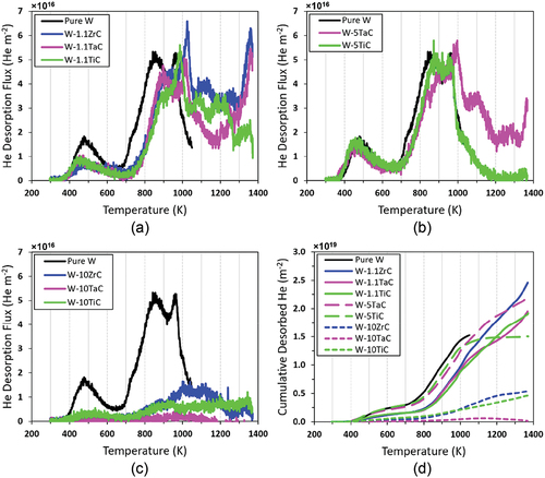
shows the cumulative amount of He desorbed from each sample as a function of temperature. It is clear that He release from the pure W sample begins at earlier temperatures and desorbs more in intermediate temperatures from 700 to 1000 K than the DS-W samples. For all three 1.1 wt% DS-W alloys, the cumulative desorption keeps increasing above 1000 K, indicating He is trapped at some high-energy traps in these alloys. The W-5TiC and W-5TaC alloys show similar behavior up to ~1000 K. Beyond 1000 K, the W-5TiC sample exhibits little desorption, while the W-5TaC sample shows significantly more desorption. In the 10 wt% alloys, there is very little desorption at all, but most desorption occurs at temperatures above 800 K, indicating a significant amount of high-energy trap sites. This indicates that concentration effects influence the high-energy trapping behavior in the alloys through the introduction of a greater number of second-phase dispersoids, which is discussed in Sec. IV.
The total amount of desorbed He is given in . Note this does not represent the total amount of He retained in the samples, but the total amount of He desorbed up to 1373 K. Note that due to the lack of data above 1050 K for pure W, the total He desorbed from pure W is less than what would have been released up to 1373 K and may not be directly comparable to the other samples. In order to account for total He retention in the sample, the sample must be heated potentially beyond 2150 K (CitationRef. 26). In all, the 1 and 5 wt% alloys showed similar desorption, while the 10 wt% alloys desorbed significantly less He than the other DS-W alloys. In addition, the He desorption of the 10 wt% alloys was much lower than the pure W for temperatures less than 1100 K.
TABLE I Average Bubble Diameter within the W Grains and Dispersoids, and Total Amount of Desorbed He
III.B. Post-TDS Microstructure
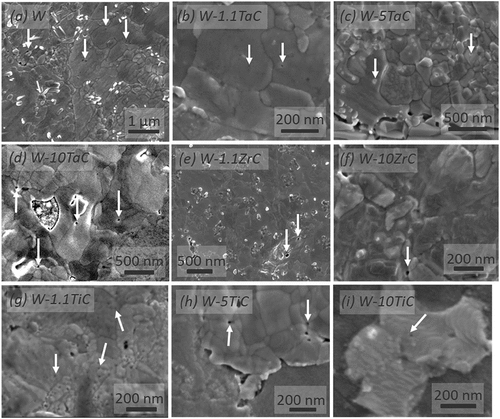
The SEM micrographs in through show the presence of surface nanopores after TDS. The presence of these pores can be attributed to He release at the surface. Additionally, the gaps between W grains and dispersoids indicate delamination between the dispersoids and W grains on the DS-W (, and ). The decohesion may be due to He release at the boundaries or thermal grooving, as thermal grooving is observed at the W-W grain boundaries as well. No subsurface pores are observed in FIB-SEM cross-section imaging.
Fig. 2. SEM micrographs in as-indicated samples of the surface morphology post TDS. Surface pores and delamination can be observed and attributed to He release. White arrows indicate surface pores.
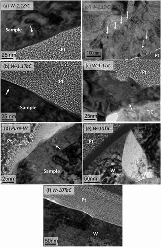
In order to understand residual He residence in the samples, post-TDS TEM analysis was undertaken. though 3f show TEM micrographs with FIB-deposited platinum (Pt) used to protect the sample surface during the FIB process. The sample names are labeled in each figure, and representative bubbles are indicated with arrows. The micrographs show subsurface He bubbles within the W grains, but not at the W-W grain boundaries or at the W-dispersoid boundaries. None of the bubbles are faceted, indicating equilibrium He gas pressure inside the bubble, which is attributed to He agglomeration at the bubbles during the TDS experiment. All bubbles in the W grains are within ~50 nm of the sample surface. The average bubble sizes in the W grains are shown in . Only the W-1.1ZrC sample displayed bubbles within the dispersoids (shown in ’), with dispersoid bubbles being larger and present deeper beneath the sample surface. No He bubbles were observed anywhere in the 10 wt% alloys as shown in and . Although TEM images are not presented here, our TEM analysis found that no He bubbles within the W grains, dispersoids, or at the boundaries were formed in the W-5TaC or W-10ZrC samples either. For the 10 wt% samples, very little He release was observed in the TDS. XPS analysis showed that oxide content was larger for samples with 10 wt% dispersoid concentrations than the 1.1 wt% samples. W-1.1TaC and W-1.1TiC showed ~4 at. % oxygen concentration, while W-10TiC showed an ~8 at. % oxygen concentration. A more detailed sample chemistry analysis will follow in future work.
Fig. 3. TEM micrographs post TDS showing the presence of He bubbles within the W grains of (a) W-1.1ZrC, (a’) dispersoid in W-1.1ZrC, (b) W-1.1TaC, (c) W-1.1TiC, (d) pure W, (e) W-10TiC, and (f) W-10TaC. The FIB-deposited Pt and TEM lamella (sample) are identified. Representative bubbles within the samples are identified with arrows. No helium bubbles were observed at the W-W grain boundaries or the W-dispersoid boundaries, or in the 10 wt% specimens anywhere.
IV. DISCUSSION
The He release peaks observed in the pure W agree with prior work in this area.Citation15,Citation26–31 The low-temperature peak around 500 K is thought to be associated with He release from dislocation loops, although there is no consensus.Citation15,Citation26,Citation34,Citation35 The peaks at 850 and 960 K are thought to be from grain boundaries and low-energy He-V complexes. Peaks at higher temperatures are associated with He clusters, with larger He-V clusters exhibiting He release at lower temperatures.Citation35 Fu et al. noted that release from intragranular He bubbles may not occur until 1600 K, thus intragranular He bubbles were not expected to be completely desorbed at 1350 K in this study, confirming the presence of He bubbles within the W grains post-TDS in the pure W sample studied here.Citation29 Xu et al. observed nanosized He bubbles within the W grains after annealing to 1373 K, and further growth after annealing to 1773 K (CitationRef. 36). The nanopores and grain boundary blisters observed in on the W grains suggest He release there, and mirrors a result seen by Fu et al. and El-Atwani et al. after TDS of the He-implanted W (CitationRefs. 15 and Citation29). However, the grain size distribution and He irradiation/implantation conditions do differ in this study compared to CitationRefs. 15 and Citation29.
The desorption spectra of the DS-W specimens, while similar across compositions at the same carbide concentration, however, differed compared to pure W, indicating that the addition of the dispersoids impacts the He trapping and thus the release temperatures. The thermal desorption release peaks are shifted to higher temperatures compared to pure W. The shift to slightly higher release temperatures indicates stronger trapping, a result similar to Zhou et al. who found slightly higher release temperatures in a W-Ta composite compared to pure W (CitationRef. 37). There are two main mechanisms likely for altering the He desorption in the alloys: grain size reduction and dispersoid chemistry.
Finer grains correlate with a shorter diffusion pathway to grain boundaries. El-Atwani et al. observed more overall and more high-temperature desorption in nanocrystalline W (CitationRef. 15). In the study presented here, as the dispersoids were added, the W grain size decreased from ~12 µm in pure W to ~7, ~5, and ~2 µm in the 1.1, 5, and 10 wt% DS-W specimens, respectively. Grain boundary density increased by ~3.5× from the 1.1 to the 10 wt% samples. The decrease in grain size and increase in grain boundary density may contribute to the altered desorption spectra. However, we do not reach the nanocrystalline grain regime in the samples that were studied by El-Atwani et al.Citation15 Therefore, the grain boundary density in the DS-W samples is still well below the levels in the nanocrystalline W samples, significantly altering the He desorption.
Due to the temperature of irradiation being 1073 K, He will be desorbing from the specimens during the irradiation. Therefore, in the 10 wt% specimens that have smaller grains, desorption during the irradiation will be enhanced compared to the coarse-grained 1.1 wt% specimens as the W grain boundaries may act as short paths for He release during the irradiation. Therefore, less He may be retained in the 10 wt% alloy specimens after irradiation but before TDS, which may contribute to less He desorbed during the TDS analysis as shown in . In general, across all samples, it is important to recognize that desorption occurred during the irradiation of the samples. Nevertheless, considering the limited increase in grain boundary density but the substantial decrease in He desorption in the 10 wt% samples compared to the 1.1 wt% samples, it is likely that the dispersoid chemistry also played a critical role in modifying the He desorption behaviors in the DS-W alloys.
In the 1.1 wt% alloys, the dispersoid concentration was small, such that the total He release was not significantly different from that of pure W. Up until 1100 K, the total amount of desorbed He was only slightly less in the 1.1 wt% alloys, indicating a small impact of dispersoid chemistry as the volume fraction of the dispersoids is low. On the 10 wt% samples shown in and significantly lower amount of He was desorbed and there were no bubbles observed in the post-TDS TEM images in either the W grains or dispersoid grains, nor any grain boundaries. The lower desorption compared to pure W is in direct contrast to studies by Buzi et al. who found enhanced He desorption in W-20Ti alloys versus pure W (CitationRef. 38). The difference here compared to CitationRef. 38 may be attributed to dispersoid chemistry or differences in grain size.
The transition metal carbides that were added to capture impurity oxygen atoms from the W matrix resulted in a mixed metal-oxygen-carbon composition.Citation18,Citation32 In oxide ceramics there is a complex interplay between oxygen concentrations and the corresponding impact on He mobility and trapping. Nonstoichiometric ZrOx has been correlated with increased trapping and the high-temperature release of He and Xe (CitationRefs. 39 through 45). Similarly, nonstoichiometric TiOx and oxygen-implanted titanium have been shown to limit He agglomeration, with oxygen implantation increasing He trapping near the oxygen implantation zone.Citation46,Citation47 First-principles studies have shown that He occupancy in TiO2 is related to the oxygen concentration, and there is a high He migration barrier and low He-He interaction energy in TiO2 as compared to W (CitationRefs. 48 and Citation49), indicating that the He that is trapped in the dispersoids may not accumulate to visible bubbles and will not be released at the temperatures studied here. Due to the nonstoichiometric nature of the mixed metal-oxy-carbide dispersoids in the DS-W specimens,Citation18,Citation32 it is hypothesized that they resemble TiOx and ZrOx in how oxygen affects the He behavior, causing no thermal release at low temperatures.
The pre-TDS XPS analysis showed that irradiated samples with larger concentrations of dispersoids led to higher concentrations of oxygen within the samples. It follows that the higher oxygen content in the 10 wt% samples could lead to more trap sites and contribute to significantly reduced He desorption up to 1350 K. The finer grain size in the 10 wt% specimens also means there is a greater likelihood for He to interact with a dispersoid. The 10 wt% samples showed very limited release up to 1350 K, thus supporting our hypothesis of the oxide effects on He release. Thus, He that is trapped in the nonstoichiometric metal-carbon-oxygen dispersoids was not released up to 1350 K. However, further investigation about He interactions with dispersoids using techniques such as atom probe tomography would allow for further analysis to experimentally support our findings.
The reasons for the similar desorption profile for the 5 wt% samples to the pure W are still under investigation. However, the 5 wt% alloys have a complex interplay of grain size reduction and dispersoid concentration. The samples have a ~0.7× smaller W grain size and a 5× larger dispersoid concentration compared to the 1.1 wt% alloys. Compared to the 10 wt% alloys, they have a lower dispersoid concentration and larger W grains. Therefore, it is proposed that there is a balance between the mechanisms offered earlier that leads to no significant changes to the total amount of desorbed He. Future work will also look to see how oxygen concentration plays a role in these 5 wt% alloys.
The diverging spectra of the W-5TiC and W-5TaC samples above 1000 K may be due to differences in the size and spatial distribution of the dispersoids, with the W-5TiC sample having smaller and more dispersed TiC dispersoids. The TiC dispersoids were smaller and more evenly distributed throughout the samples at the grain boundaries and within the grains, whereas the TaC samples had larger dispersoids concentrated at the grain boundaries. Therefore, having more dispersoids and more within the grains could provide more pinning sites for He to be trapped, preventing He release at high temperatures and causing it to differ from the TaC samples. This effect would be most apparent on the 5 wt% samples. However, future modeling studies are needed to elucidate the exact mechanisms responsible for the differences between the W-TaC and W-TiC samples.
V. CONCLUSIONS
In this work, the thermal desorption behavior of helium from DS-W alloys was investigated. After 225-eV He irradiation at 1073 K, TDS was performed to analyze the He desorption characteristics up to 1350 K. Compared to pure W, the samples alloyed with 1.1 and 5 wt% added TaC, TiC, or ZrC desorbed more He, with the desorption peaks shifted to higher temperatures, indicating higher-energy trap sites. Post-TDS microscopy showed He bubbles within the W grains on these samples only, with bubbles only within some ZrC dispersoids on the W-1.1ZrC specimen. No bubbles were observed at the W-W grain boundaries or W-dispersoid interfaces.
The 10 wt% samples all exhibited significantly decreased He desorption, and no presence of He bubbles was detected anywhere in the specimens via microscopy. The mixed carbon and oxygen chemistry within the dispersoids is thought to be trapping He atoms in high concentrations of TEM-invisible, high-energy trapping sites that are not desorbed up to 1350 K.
This work shows that under low-fluence He irradiation, low-alloyed DS-W materials have similar He retention behavior as pure W, but if the alloying concentration is increased, He retention is significantly altered due to the mixed metal-oxygen-carbide system within the W matrix, which may affect fuel inventory and plasma-facing material performance in a future reactor if nonmonolithic W is used.
Acknowledgments
This characterization was carried out in part in the Frederick Seitz Materials Research Laboratory Central Research Facilities, University of Illinois.
Disclosure Statement
No potential conflict of interest was reported by the authors.
Additional information
Funding
References
- Y. UEDA et al., “Baseline High Heat Flux and Plasma Facing Materials for Fusion,” Nucl. Fusion, 57, 9, 092006 (2017); https://doi.org/10.1088/1741-4326/aa6b60.
- R. A. PITTS et al., “A Full Tungsten Divertor for ITER: Physics Issues and Design Status,” J. Nucl. Mater., 438, S48 (2013); https://doi.org/10.1016/j.jnucmat.2013.01.008.
- S. J. ZINKLE and N. M. GHONIEM, “Operating Temperature Windows for Fusion Reactor Structural Materials,” Fusion Eng. Des., 51–52, 55 (2000); https://doi.org/10.1016/S0920-3796(00)00320-3.
- O. EL-ATWANI et al., “Helium Bubble Formation in Ultrafine and Nanocrystalline Tungsten Under Different Extreme Conditions,” J. Nucl. Mater., 458, 216 (2015); https://doi.org/10.1016/j.jnucmat.2014.12.095.
- L. LIU et al., “High-Flux He+ Irradiation Effects on Surface Damages of Tungsten Under ITER Relevant Conditions,” J. Nucl. Mater., 471, 1 (2016); https://doi.org/10.1016/j.jnucmat.2016.01.001.
- F. SEFTA et al., “Tungsten Surface Evolution by Helium Bubble Nucleation, Growth and Rupture,” Nucl. Fusion, 53, 073015 (2013); https://doi.org/10.1088/0029-5515/53/7/073015.
- S. SHARAFAT et al., “A Description of Bubble Growth and Gas Release of Helium Implanted Tungsten,” J. Nucl. Mater., 389, 203 (2009); https://doi.org/10.1016/j.jnucmat.2009.02.027.
- S. KAJITA et al., “Formation Process of Tungsten Nanostructure by the Exposure to Helium Plasma Under Fusion Relevant Plasma Conditions,” Nucl. Fusion, 49, 095005 (2009); https://doi.org/10.1088/0029-5515/49/9/095005.
- M. MIYAMOTO et al., “In Situ Transmission Electron Microscope Observation of the Formation of Fuzzy Structures on Tungsten,” Phys. Scr., T159, 014028 (2014); https://doi.org/10.1088/0031-8949/2014/T159/014028.
- M. J. BALDWIN and R. P. DOERNER, “Helium Induced Nanoscopic Morphology on Tungsten Under Fusion Relevant Plasma Conditions,” Nucl. Fusion, 48, 035001 (2008); https://doi.org/10.1088/0029-5515/48/3/035001.
- K. WANG et al., “Morphologies of Tungsten Nanotendrils Grown Under Helium Exposure,” Sci. Rep., 7, 42315 (2017); https://doi.org/10.1038/srep42315.
- K. WANG et al., “Effect of Starting Microstructure on Helium Plasma-Materials Interaction in Tungsten,” Acta Mater., 124, 556 (2017); https://doi.org/10.1016/j.actamat.2016.11.042.
- D. DONOVAN et al., “Characterization of He-Induced Bubble Formation in Tungsten due to Exposure from an Electron Cyclotron Resonance Plasma Source,” Fusion Sci. Technol., 72, 337 (2017); https://doi.org/10.1080/15361055.2017.1333856.
- O. EL-ATWANI et al., “Ultrafine Tungsten as a Plasma-Facing Component in Fusion Devices: Effect of High Flux, High Fluence Low Energy Helium Irradiation,” Nucl. Fusion, 54, 083013 (2014); https://doi.org/10.1088/0029-5515/54/8/083013.
- O. EL-ATWANI et al., “Thermal Desorption Spectroscopy of High Fluence Irradiated Ultrafine and Nanocrystalline Tungsten: Helium Trapping and Desorption Correlated with Morphology,” Nucl. Fusion, 58, 016020 (2018); https://doi.org/10.1088/1741-4326/aa86cf.
- M. YAMAGIWA et al., “Helium Bubble Formation on Tungsten in Dependence of Fabrication Method,” J. Nucl. Mater., 417, 499 (2011); https://doi.org/10.1016/j.jnucmat.2011.02.007.
- X. LIU et al., “Irradiation Effects of Hydrogen and Helium Plasma on Different Grade Tungsten Materials,” Nucl. Mater. Energy, 12, 1314 (2017); https://doi.org/10.1016/j.nme.2017.01.018.
- E. LANG et al., “Microstructural and Compositional Effects of Transition Metal Carbide Additions on Dispersion-Strengthened Tungsten Fabricated via Spark Plasma Sintering,” Int. J. Refract. Met. Hard Mater., 75, 279 (2018); https://doi.org/10.1016/j.ijrmhm.2018.04.015.
- H. KURISHITA et al., “Development of Re-crystallized W–1.1%TiC with Enhanced Room-Temperature Ductility and Radiation Performance,” J. Nucl. Mater., 398, 1, 87 (2010); https://doi.org/10.1016/j.jnucmat.2009.10.015.
- Z. M. XIE et al., “Extraordinary High Ductility/Strength of the Interface Designed Bulk W-ZrC Alloy Plate at Relatively Low Temperature,” Sci. Rep., 5, 16014 (2016); https://doi.org/10.1038/srep16014.
- M. J. BALDWIN and R. P. DOERNER, “Formation of Helium Induced Nanostructure ‘Fuzz’ on Various Tungsten Grades,” J. Nucl. Mater., 404, 3, 165 (2010); https://doi.org/10.1016/j.jnucmat.2010.06.034.
- M. J. BALDWIN et al., “Experimental Measurements and Modeling of the Deuterium Release from Tungsten Co-deposited Layers,” Nucl. Mater. Energy, 23, 100743 (2020); https://doi.org/10.1016/j.nme.2020.100743.
- H. T. LEE et al., “Hydrogen and Helium Trapping in Tungsten Under Single and Sequential Irradiations,” J. Nucl. Mater., 360, 2, 196 (2013); https://doi.org/10.1016/j.jnucmat.2006.09.013.
- M. SHIMADA et al., “Deuterium Retention in Neutron-Irradiated Single-Crystal Tungsten,” Fusion Eng. Des., 136, B 1161 (2018); https://doi.org/10.1016/j.fusengdes.2018.04.094.
- L. M. GARRISON, F. W. MEYER, and M. E. BANNISTER, “The Influence of Microstructure on Deuterium Retention in Polycrystalline Tungsten,” Fusion Sci. Technol., 72, 4, 574 (2017); https://doi.org/10.1080/15361055.2017.1352431.
- Y. GASPARYAN, V. EFIMOV, and K. BYSTROV, “Helium Concentration Measurement in Tungsten Fuzz-Like Nanostructures by Means of Thermal Desorption Spectroscopy,” Nucl. Fusion, 56, 054002 (2016); https://doi.org/10.1088/0029-5515/56/5/054002.
- S. RYABSTEV et al., “Helium Retention in Tungsten Irradiated with He+ Ion Beam at Elevated Temperatures,” Nucl. Instrum. Methods Phys. Res., Sect. B, 460, 1, 108 (2019); https://doi.org/10.1016/j.nimb.2019.01.051.
- Y. GASPARYAN et al., “Helium Retention in Tungsten Under Plasma and Ion Beam Irradiation and Its Impact on Surface Morphology,” Phys. Scr., 2020, T171, 014017 (2020); https://doi.org/10.1088/1402-4896/ab4068.
- Z. FU et al., “Thermal Desorption and Surface Modification of He+ Implanted into Tungsten,” J. Nucl. Mater., 329–333, A, 692 (2004); https://doi.org/10.1016/j.jnucmat.2004.04.190.
- K. TOKUNAGA et al., “Surface Morphology and Helium Retention on Tungsten Exposed to Low Energy and High Flux Helium Plasma,” J. Nucl. Mater., 313–316, 92 (2014); https://doi.org/10.1016/S0022-3115(02)01362-4.
- O. V. OGORODNIKOVA et al., “Deuterium and Helium Retention in W with and Without He-Induced W ‘Fuzz’ Exposed to Pulsed High-Temperature Deuterium Plasma,” J. Nucl. Mater., 515, 150 (2019); https://doi.org/10.1016/j.jnucmat.2018.12.023.
- E. LANG et al., “Deciphering the Role of Second Phase Precipitates on Eearly-Stage Surface Morphology Development of Dispersion-Strengthened W Alloys Under Low Energy He Irradiation,” Nucl. Mater. Energy, 19, 47 (2019); https://doi.org/10.1016/j.nme.2019.01.016.
- J. SCHINDELIN et al., “Fiji: An Open-Source Platform for Biological-Image Analysis,” Nat. Methods, 9, 7, 676 (2012); https://doi.org/10.1038/nmeth.2019.
- H. T. LEE et al., “Hydrogen and Helium Trapping in Tungsten Under Single and Sequential Irradiations,” J. Nucl. Mater., 360, 2, 196 (2007); https://doi.org/10.1016/j.jnucmat.2006.09.013.
- E. V. KORNELSEN, “The Interaction of Injected Helium with Lattice Defects in a Tungsten Crystal,” Radiation Effects, 13, 3–4, 227 (1972); https://doi.org/10.1080/00337577208231184.
- Q. XU et al., “Retention and Thermal Desorption of Helium in Pure Tungsten,” Philos. Mag. Lett., 96, 12, 477 (2016); https://doi.org/10.1080/09500839.2016.1260175.
- H. ZHOU et al., “Large Plastic Deformation Blistering and Helium Retention in 5% Tantalum Doped Tungsten Under 60 keV Helium Ions Implantation,” Fusion Eng. Des., 134, 43 (2018); https://doi.org/10.1016/j.fusengdes.2018.06.014.
- L. BUZI et al., “Deuterium and Helium Ion Irradiation of Nanograined Tungsten and Tungsten-Titanium Alloys,” Nucl. Mater. Energy, 21, 100713 (2019); https://doi.org/10.1016/j.nme.2019.100713.
- S. AGARWAL et al., “Helium Induced Microstructure Damage, Nano-scale Grain Formation and Helium Retention Behaviour of ZrC,” Acta Mater., 163, 14 (2019); https://doi.org/10.1016/j.actamat.2018.09.062.
- Y. PIPON et al., “Influence of the Oxygen Content on the Thermal Migration of Xenon in ZrCxO1-x,” J. Nucl. Mater., 440, 1–3, 546 (2013); https://doi.org/10.1016/j.jnucmat.2013.03.015.
- J. MATSUNAGA et al., “Dependence of Vacancy Concentration on Morphology of Helium Bubbles in Oxide Ceramics,” J. Nucl. Sci. Technol., 51, 1231 (2014); https://doi.org/10.1080/00223131.2014.918526.
- J.-M. COSTANTINI et al., “Nuclear Reaction Analysis of Helium Migration in Zirconia,” J. Nucl. Mater., 321, 2–3, 281 (2003); https://doi.org/10.1016/S0022-3115(03)00280-0.
- G. VELISA et al., “He Implantation in Cubic Zirconia: Deleterious Effect of Thermal Annealing,” J. Nucl. Mater., 402, 1, 87 (2010); https://doi.org/10.1016/j.jnucmat.2010.05.001.
- G. GUTIERREZ et al., “High Temperature Annealing of Xe Implanted ZrC0.95O0.05 Investigated by RBS, TEM and PAS-DBS,” Prog. Nucl. Energy, 57, 57 (2012); https://doi.org/10.1016/j.pnucene.2011.10.007.
- P. M. G. DAMEN et al., “Thermal Annealing Behaviour and Defect Evolution of Helium in Fully Stabilised Zirconia,” J. Nucl. Mater., 319, 65 (2003); https://doi.org/10.1016/S0022-3115(03)00135-1.
- Y. BABA and T. A. SASAKI, “XPS and TDS Studies of Trapping States of Helium Implanted into TiO2,” J. Nucl. Mater., 152, 295 (1988); https://doi.org/10.1016/0022-3115(88)90340-6.
- M. B. LEWIS, “Evidence for Helium Trapping to Oxygen Sites in Titanium,” Nucl. Instrum. Methods Phys. Res., 22, 4, 499 (1987); https://doi.org/10.1016/0168-583X(87)90149-2.
- P. ERHART, “A First-Principles Study of Helium Storage in Oxides and at Oxide-Iron Interfaces,” J. Appl. Phys., 111, 113502 (2012); https://doi.org/10.1063/1.4707944.
- J. G. NIU, Q. ZHAN, and W. T. GENG, “Waltzing of a Helium Pair in Tungsten: Migration Barrier and Trajectory Revealed from First-Principles,” AIP Adv., 4, 6, 067128 (2014); https://doi.org/10.1063/1.4884304.