
Abstract
The Karlsruhe Tritium Neutrino (KATRIN) experiment measures the tritium β-spectrum close to the maximum decay energy to achieve the value of the electron-antineutrino mass with a sensitivity of 0.2 eV/c2 (90% confidence level). Since only a small fraction of the decay electrons carries nearly all the energy, a high luminous tritium source, with its supporting infrastructure facilities, is necessary.
Since the start of the tritium operation of KATRIN back in May 2018, more than 600 days of 24/7 measuring campaigns with a total tritium throughput of ≈18.1 kg and a tritium concentration >95% have been conducted. Despite several technical issues occurring during the run time, the necessary reliable supply of tritium was provided. This contribution will give an overview of the current operational conditions of the Tritium Laboratory Karlsruhe tritium facilities involved, as well as the relevant technical, analytical, and administrative procedures implemented. Furthermore, an analysis will be given for system and component malfunctions in the tritium loop as well as the associated actions for problem-solving and repair. In addition, an end-of-life investigation for the component failure will be presented.
I. INTRODUCTION
The Tritium Laboratory Karlsruhe (TLK) research activities were initially focused on developing technical tritium handling techniques and processes in view of the fuel cycle of future fusion power plants.[Citation1–4] Currently, the main task is to host the Karlsruhe Tritium Neutrino (KATRIN) experiment and the operation of the related tritium facilities. KATRIN measures the tritium β-spectrum close to the maximum decay energy. A distortion of the electron spectrum in this region contains information about the neutrino mass. To achieve the determination of the electron-antineutrino mass with a sensitivity of 0.2 eV/c2 (90% confidence level), a high-luminosity tritium source is paramount.[Citation5] KATRIN realizes this by using a windowless gaseous tritium source (WGTS). The operational parameters of the WGTS are a gas throughput of ≈40 g/day with a tritium concentration >95% circulated in the KATRIN inner loop. The TLK infrastructure facilities provide all the necessary operations to maintain the tritium concentration.[Citation6] A detailed description of the tritium-loop in KATRIN is presented in Ref. [Citation7]
To ensure the continuous operation of KATRIN, other experiments, and the tritium infrastructure in general, several technical, analytical, and administrative procedures have been implemented.
In the following sections, a summary of 4 years of tritium operation, the implemented procedures, their changes as we gained experienced, and some critical technical malfunctions and their solutions are presented.
II. SUMMARY OF OPERATION SINCE 2019
In , a simplified version of key parts of the outer tritium loop is shown. The KATRIN inner loop is fed from the tritium transfer system (TTS) batchwise with a tritium concentration >98%. From the KATRIN inner loop system, retentate batches containing hydrogen-isotopologues and waste gas (like 3He) are first transferred to the isotope recovery system CAPER. By passing a palladium membrane filter (permeator), hydrogen-isotopologues are separated from all other gases. Chemically bound tritium is stored in CAPER and batchwise recovered in a catalytic process.[Citation8] The permeate, containing all hydrogen-isotopologues, is transferred to the TTS. In this facility, accountancy is performed with a combination of pressure and temperature sensors, precisely known volumes and concentration measurement analytics like laser Raman spectroscopy (LARA).[Citation9,Citation10] To separate tritium from hydrogen and deuterium, the gas mixture is transferred to the Isotope Separation System (ISS), which uses displacement gas chromatography. The ISS is capable of enriching gas mixtures to a tritium concentration >99%.
Fig. 1. Simplified graph of relevant parts of the KATRIN tritium outer loop as well as key figures in 4 years of tritium operation.
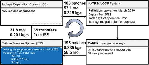
The full KATRIN tritium operation started in March 2019.[Citation11] Since then, more than 600 days of operations have been conducted, and the tritium in KATRIN was replenished ≈100 times. CAPER received and processed ≈195 gas batches from the inner loop. Chemically bound tritium had to be recovered using 31 individual processing batches with a total amount of 37 mol processed. A total of 120 isotope separations resulted in 31.8 mol tritium–enriched gas mixtures. Including the support processes, a total of ≈676 transfers with a total amount of ≈301 mol containing ≈1.5 kg tritium were performed in the TLK outer loop. The tritium throughput in the inner loop up to now amounts to ≈18.1 kg, while only ≈0.3 kg has been circulated in the outer loop.
III. OPERATIONAL EXPERIENCE
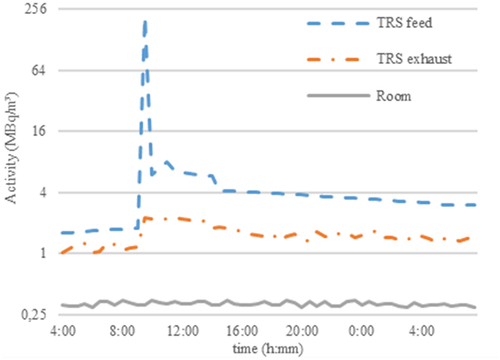
The TLK technical and administrative standards and processing procedures were successfully validated during the safe and reliable operation of the KATRIN tritium loops. This holds true even during events causing an elevated activity concentration of a glove-box atmosphere (>100 MBq/m3), as shown in . This proves the effectiveness of the TLK multibarrier concept.
Fig. 2. Activity measurement from a tritium retention system during an increased tritium release into the glove box from a defective sampling container.
Tasks with a higher incorporation risk have to follow a strict supervised procedure. In this process, the responsible radiation protection officer and operator, as well as a radiation protection specialist, are involved to individually set and monitor proven safety measures, such as directed flow control and surface contamination measurements.
The facilities that now form the KATRIN outer loop were originally experiments showing the feasibility of a closed tritium cycle for a fusion reactor, and therefore, are not optimized for the KATRIN-related processes. To improve the performance, a dedicated isotope recovery system Abgasreinigungssystem(AGR) is planned and is currently being set-up. This will result in a greatly reduced amount of components to maintain, as shown in , as well as shorter processing times.
TABLE I Component Quantity Comparison of the Existing Isotope Recovery Facility CAPER with the Designated AGR Facility
To validate the success after an isotope separation, the compositions of the enriched and depleted gas fractions need to be measured. In the past, the only facility equipped with a tritium concentration measurement system (LARA[Citation9]) in the infrastructure of TLK was the TTS. Measurements are performed batchwise and can take up to 2 h. To improve the overall processing times, concentration measurement systems [inline Raman system (µRa)[Citation10]/mass spectrometry] have been installed in the processing facilities ISS and CAPER. To measure the absolute tritium concentrations, beta-induced X ray spectrometry (BIXS)[Citation12] was installed in the TTS. Besides the operational experience gained, the knowledge about component behavior in practical applications is most valuable.
IV. TECHNICAL FAILURES AND THEIR SOLUTIONS
provides an overview of selected primary system components at the KATRIN tritium loop. Components such as tritium compatible valves are easy to obtain and replace. With components that have supply shortages or long lead times, it is mandatory to estimate the number of components necessary to be replaced during the expected lifetime of the experiment and/or whole laboratory. Once a component is installed in a glove box and is contaminated, reliability, accessibility, and maintainability are key to the operation of a facility. In the following sections, some prominent component failures during the last 4 years of TLK operation are presented.
TABLE II Overview of Selected Relevant Primary System Components in the KATRIN Tritium Loop with the Sum of Defects in 4 Years of Tritium Operation
IV.A. Metal Bellow Pumps
After an estimated run time of less than 2000 h, the first pump installed into KATRIN, a Senior Aerospace MB601 DC, malfunctioned. The pressure switch monitoring the bellow indicated an internal leakage. The pump was the first stage of the vacuum system in the exhaust loop of KATRIN and has mostly transferred the humid gas (50% ambient humidity) of the new installed components. The leak occurred shortly after evacuating 100 L of moist air with a high load.
In the KATRIN-circulation loop, another MB601 malfunctioned and was replaced after an estimated run time of 10 000 to 15 000 h. An investigation showed a defect outer bellow of the second stage.
After an estimated run time of 15 000 h, a magnetically coupled INTERATOM metal bellow pump malfunctioned. A leakage was signaled by the pressure switch. Again, the failure was related to the atmosphere pumped from the connected vacuum system, this time at the TTS. This vacuum system is often used to evacuate a glove-box atmosphere from sampling ports; hence it can contain humidity in some cases.
The final defect was again a MB601 metal bellow pump that stopped after an estimated run time of 10 000 to 15 000 h. The pump was part of the KATRIN-DPS vacuum system. An investigation showed that the motor shaft was stuck, most likely due to a defective bearing. Because of the location of the pump, it was not possible to replace the unit. Instead, an already installed 100-L buffer vessel was rerouted to be used as a passive pump.
IV.B. Scroll Pumps
Scroll pumps, like the Normetex Model 15, are an important part in the tritium handling facilities. This type was, until recently, the only full-metal second-stage vacuum pump available.
After 20 years of service, the first Normetex Model 15 scroll pump in the TLK failed. An onsite investigation showed that the pump shaft was stuck. To further investigate, the pump was transferred to the repair box.
After the transfer, the shaft could rotate a 3/4-turn, most likely due to vibrations while in transit. While turning, scratch vibrations due to contact between the scrolls occurred. The disassembly revealed several defects.
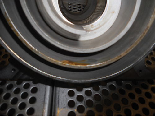
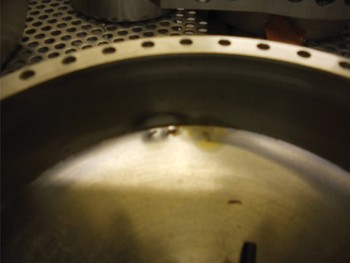
As shown in , corrosion marks are found at the fixed and orbiting scroll as well as the other parts connected with the pumping volume. Furthermore, both scrolls showed temper colors and damages with the form of the opposite spiral indicating contact between them. Before reassembly, rust and temper colors were removed. To protect the glove box from dust, a foil tent was constructed. All machining operations were performed inside the tent.
Fig. 3. Corrosion marks and temper colors at the orbiting scroll.
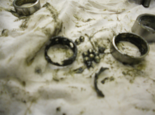
The Normetex Model 15 scroll pump has three shafts with four bearings each. The disassembly of the shaft mountings showed a broken gear cage at one of the bearings, as shown in . It is unlikely that the broken bearing cage was the cause of the initial crash, but like the temper colors, one of the consequences. A new cage was manufactured and reassembled. No other shaft mount showed any damage.
Fig. 4. Broken ball bearing cage Normetex model 15.
To enclose the pumping volume between the spirals, a cover is mounted on the orbiting scroll, as shown in . This cover shows a dent with surrounding temper colors that match the position of similar damage found at the static scroll. Most likely, the initial crash derailed the orbit of the movement to an extent such that these two components collided. After reassembly, the pump rotated freely. The reassembled pump achieved a pressure difference of 100 mbar with a total pressure of 200 mbar at the outlet. This performance was not sufficient. It is currently unknown whether the performance loss was because of an internal leak or the spacing of the spirals. It is also not known whether the spirals were set to one another in a force-fitting or in a form-fitting manner. The latter would mean that the examined pump cannot be restored since parts were probably plastically deformed.
Fig. 5. Dent with surrounding temper colors at the cover of the scrolls.
IV.C. Turbomolecular Pumps
In KATRIN and most vacuum pump systems in the TLK, turbomolecular pumps (TMPs) are used. Close to the KATRIN beam line, inside the magnetic field, shielded Leybold MAG W2800 are used. General workhorses in vacuum pump systems are Pfeiffer HiPace 80–300 pumps.
The MAG W2800 pumps at KATRIN operate 24/7 during a measurement phase at full speed and during maintenance breaks at idle speed. These pumps have been in operation quasi constantly since mid-2018 with no mechanical failure. The magnetic shielding used for the TMPs has worked as foreseen, protecting the units from magnetic stray fields, but three controller units have malfunctioned, two during operation and one during an electrical safety test.
IV.D. Valves
Several valves have had to be exchanged over the last years. The main cause was internal leakage. The used valves were typically metal bellow or diaphragm valves either equipped with full-metal or polyimide (Vespel) tips/seats. They are specified with an external leak rate of 10−9 mbar l s−1 and an internal leakage of 10−6 mbar l s−1. Most valves exceed this specification to a nonnoticeable internal leakage. Furthermore, most manual valves are used as temporary or intervention shutoff valves, therefore an internal leakage is not critical. In the past 4 years we have changed 15 valves.
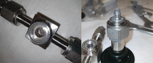
An intervention valve in the ISS primary system showed a severe internal leakage. The following inspection revealed a nontritium compatible stem tip, as shown in . Because the difference in the article number regarding the material of the tip is only one (different) letter, failures like this happen if the inspection procedure prior to installation is not thoroughly followed. Therefore, an extra step in our commissioning and change management system has been added to double check the component suitability.
Fig. 6. Inspection hand valve with a tritium incompatible tip. Radiochemical processes dissolved the tip, rendering the valve unusable.
IV.E. Flow Monitors
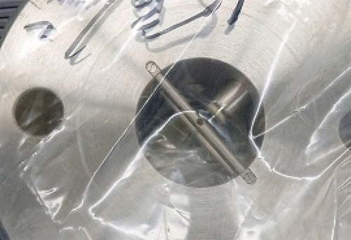
In , a simplified scheme of the central tritium retention system (ZTS) is shown. Originally, mechanical flow monitors were used to monitor the gas flow of the blowers responsible for maintaining the below-atmospheric pressure for the glove boxes. Although these are designed for continuous operation, in practice they fail over time. The turbines and their bearing points are not designed to withstand the fast flow reversal that occurs when the active line is changed, resulting in the failure of the bearing-turbine connection and in a loose turbine ().
Fig. 7. Simplified scheme of the ZTS.
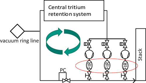
Fig. 8. Defective flowmeter from the ZTS without its turbine.
Due to the importance of the ZTS, all flow monitors have been replaced with thermal flowmeters. These operate with no moving parts, and a practically infinite service life can be expected from them.
IV.F. Permeator
In TLK, palladium membrane filters (permeator) are used to separate hydrogen from the other gases. The membrane is designed as an array of tubes that are welded shut at one site. One permeator had to be replaced because of an increasing internal leakage, most likely at one of these welds. Because of the high contamination, it is not a viable option to repair the weld.
V. SUMMARY
In the past 4 years, we continuously operated the KATRIN tritium loops. The closed tritium loop was maintained while having a safe operation in all processes. Several technical defects had to be managed. With the opportunity to investigate components that have been subject to long exposures of tritium, valuable operational experience has been gained. Optimization potential has been identified, which is now driving the design, development, and construction of custom facilities, enhancing the capabilities of the tritium loops while making the processes more robust and efficient. To increase our measurement capabilities, a compact µRA[Citation10] was installed in the ISS, TTS, and CAPER. To measure absolute tritium concentrations, BIXS[Citation12] was installed in the TTS. To have a more efficient isotope recovery process, a dedicated system has been set up near the TTS. This will enable the CAPER facility to conduct other experiments while providing a more efficient operation in conjunction with the TTS.
Disclosure Statement
No potential conflict of interest was reported by the authors.
References
- P. SCHIRA et al., “The Tritium Laboratory Karlsruhe: Laboratory Design and Equipment,” Fusion Eng. Des., 18, 16 (1991); https://doi.org/10.1016/0920-3796(91)90101-U.
- R.-D. PENZHORN et al., “Status and Research Progress at the Tritium Laboratory Karlsruhe,” Fusion Eng. Des., 49–50, 753 (2000); https://doi.org/10.1016/S0920-3796(00).
- L. DÖRR et al., “The Closed Tritium Cycle of the Tritium Laboratory Karlsruhe,” Fusion Sci. Technol., 48, 1, 262 (2005); https://doi.org/10.13182/FST05-A924.
- U. BESSERER et al., “Tritium Experience at the Tritium Laboratory Karlsruhe,” Fusion Technol., 2, 1261 (1997).
- T. THÜMMLER et al., “Introduction to Direct Neutrino Mass Measurements and KATRIN,” Nucl. Phys. B Proc. Suppl., 229–232, 146 (2012); https://doi.org/10.1016/j.nuclphysbps.2012.09.024.
- S. WELTE et al., “Tritium Supply and Processing for the First KATRIN Tritium Operation,” Fusion Sci. Technol., 76, 3, 227 (2020); https://doi.org/10.1080/15361055.2019.1705681.
- F. PRIESTER et al., “Tritium Processing Systems and First Tritium Operation of the KATRIN Experiment,” Fusion Sci. Technol., 76, 4, 600 (2020); https://doi.org/10.1080/15361055.2020.1730118.
- M. GLUGLA et al., “Design of a Catalytic Exhaust Clean-Up Unit for ITER Fusion,” Eng. Des., 39–40, 893 (1998).
- M. SCHLÖSSER et al., “Raman Spectroscopy at the Tritium Laboratory Karlsruhe,” Fusion Sci. Technol., 67, 3, 555 (2015); https://doi.org/10.13182/FST14-T78.
- F. PRIESTER et al., “µRA—A New Compact Easy-to-Use Raman System for All Hydrogen Isotopologues,” Sensors, 22, 3952 (2022); https://doi.org/10.3390/s22103952.
- M. AKER et al., “First Operation of the KATRIN Experiment with Tritium,” Eur. Phys. J. C, 80, 264 (2020); https://doi.org/10.1140/epjc/s10052-020-7718-.
- M. RÖLLIG, “Tritium Analytics by Beta Induced X-ray Spectrometry,” PhD Thesis, Karlsruher Institut fuer Technologie, Fakultaet fuer Physik (Oct. 2015).