
 ?Mathematical formulae have been encoded as MathML and are displayed in this HTML version using MathJax in order to improve their display. Uncheck the box to turn MathJax off. This feature requires Javascript. Click on a formula to zoom.
Abstract
The requirement for a reduction of the tritium inventory of the European demonstration fusion reactor (EU-DEMO) has led to the active research and development of a continuously working pumping process termed “KALPUREX.” This process foresees the direct recycling of a large fraction of the unburnt hydrogen isotopologues via superpermeation in metal foil pumps during the burn phase. The remaining exhaust gas mixture is pumped by continuously operating, mercury-driven linear diffusion pumps. Diffusion pumps are kinetic high vacuum pumps whose pumping principle is based on the momentum transfer from a supersonic mercury vapor jet to the pumped gas mixture. Like many high vacuum pumps, they feature species-dependent pumping speeds. In the present work, we develop a simplified hybrid model of the high vacuum pumping train in order to estimate the effective pumping speed of the integrated system. The results of this model and its implications on the further development of the vacuum system are discussed for the burn and dwell phases of EU-DEMO.
I. INTRODUCTION
Unburnt fuel, composed of the hydrogen isotopologues ,Footnotea
makes up for about 98% of the exhaust gas mixture. The remaining about 2% is mainly comprised of helium, the ash of the fusion reaction, and plasma enhancement gases (PEGs), like xenon or argon (in EU-DEMO). Furthermore, small quantities of other impurities, like water (
) and hydrocarbons (e.g.,
), are expected in the exhaust gas mixture. The exact composition is not known at this time and is subject to change due to design and operating condition changes.
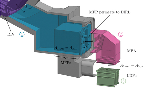
The exhaust gases are extracted from the fusion reactor torus via pumping ports that are attached below the divertor (DIV). Because of the large amount of unburnt fuel, it is very beneficial to recycle a large fraction of it directly, a concept termed direct internal recycling (DIR).[Citation1] The KALPUREX process is an implementation of the DIR concept using metal foil pumps (MFPs) for separation and primary pumping of the unburnt fuel and mercury-driven linear diffusion pumps (LDPs) for the primary pumping of the remaining part of the exhaust gases.[Citation2–4] A combination of mercury-driven booster pumps and liquid ring pumps is used as backing pumps (BPs). The separation of the exhaust gas mixture results in two loops that are referred to as the direct internal recycling loop (DIRL) for the recycled stream carrying pure hydrogenic species and the inner tritium plant loop (INTL) for the unseparated stream.[Citation4] An overview of the system is depicted in .
Fig. 1. Simplified sketch of the KALPUREX exhaust pumping process (based on Refs. [Citation2,Citation3,Citation4]). Abbreviations of the subsystems are explained in the text. The flow in the DIRL (dashed) is only active during the burn phase.
![Fig. 1. Simplified sketch of the KALPUREX exhaust pumping process (based on Refs. [Citation2,Citation3,Citation4]). Abbreviations of the subsystems are explained in the text. The flow in the DIRL (dashed) is only active during the burn phase.](/cms/asset/fd7a3912-6e8e-4c61-9951-be7cdbebc250/ufst_a_2229679_f0001_oc.jpg)
During the burn phase, both loops are active and the flow rate in the DIRL is higher than in the INTL. However, during the dwell phase, the MFPs are not operated, and therefore, the dwell pumping is supplied by the high vacuum system of the INTL. The present work aims to build a simplified model of the high vacuum system of the INTL. The central idea is to combine sophisticated models for the individual subsystems in the form of a hybrid model to estimate the integrated performance. This is extremely important to identify optimization potentials in the system during operation of the fusion reactor. While the vacuum system has to fulfill several roles, e.g., during off-normal events and maintenance, we focus on the two most important operating states (i.e., plasma burn and dwell phases) in the present work.
II. THEORY AND METHOD
II.A. Vacuum Terminology and Definitions
High vacuum pumps are characterized by the so-called pumping speed , which corresponds to the volumetric flow rate that is pumped through the inlet of the pump. Another commonly used quantity is the dimensionless capture coefficient
,[Citation5] which is defined as
where
| = | = pumped number flow rate | |
| = | = inlet cross section of the pump | |
| = | = Boltzmann constant | |
| = | = temperature | |
| = | = pressure in the recipient | |
| = | = thermal velocity of the gas with molecular mass |
For many high vacuum pumps, the pumping speed and capture coefficient are approximately constant for a given gas species irrespective of the chosen BP and for a wide range (order of magnitudes) of inlet pressures.
The available pumping speed or capture coefficient at an arbitrarily chosen cross section in the vacuum system connected to a vacuum pump is referred to as the effective pumping speed or capture coefficient. It is by definition smaller than the nominal pumping speed of the pump due to the limited conductance C of the piping. Similar to the pumping speed, the conductance corresponds to a volumetric flow rate. Its dimensionless counterpart is called transmission probability and is defined as
The important distinction to the capture coefficient [see EquationEq. (1)(1)
(1) ] is that the transmission probability is calculated under the assumption that a perfect vacuum pump, responsible for the flow rate
, is connected to the outlet of the system. Analytical expressions for the transmission probability exist only for very simple components, e.g., circular tubes. For geometrically complex structures (e.g., the EU-DEMO pumping duct), the standard procedure is to use the “test particle Monte Carlo” (TPMC) method, which works by tracing computational test particles through the component and simulating their interaction with the walls. Each simulated particle will either leave the component through the inlet or outlet surfaces. The transmission probability is then readily computed as the ratio of particles pumped (counted at outlet) to injected particles. The results for standard components (e.g., elbows) are available in tabulated form in the literature.[Citation6] The TPMC method is based on the assumption that the gas is in the free molecular regime, thus neglecting intermolecular collisions. If this assumption is not valid, the “direct simulation Monte Carlo” (DSMC) method[Citation7] can be employed. Similar to TPMC, DSMC is a statistic particle method. However, intermolecular collisions are also considered by discretizing time and space.
II.B. Ansatz of Oatley
The effective capture coefficient of complex vacuum systems can either be determined by simulating the entire system or estimated based on the properties of the involved subsystems. While the former approach yields more accurate results, the latter has the distinct advantage that the subsystems can be simulated and optimized individually using smaller, more efficient models. The “Ansatz of Oatley” is an established method to estimate the effective capture coefficient of complex vacuum systems.[Citation8–11] Conceptually, the Ansatz of Oatley is similar to the regular treatment of a series connection of resistances (as known from electric circuits) with the important inclusion of the flow direction and the corresponding interface inflow resistances. The effective capture coefficient at the inlet of a complex vacuum system, which is composed of
subsystems and connected to a vacuum pump (subsystem
), can be estimated for an isothermal system using the generalized Ansatz of Oatley:
where and
refer to the inlet and outlet cross sections of the individual subsystems, respectively. The first two terms on the right side account for the flow resistance of the involved subsystems. The last term on the right side of EquationEq. (3)
(3)
(3) accounts for reductions in the cross sections in the flow direction by considering them as orifices. Due to the assumptions made in the derivation of the Ansatz of Oatley, the subsystem transmission probabilities have to include the inflow resistance of the respective parts. In the free molecular regime, this corresponds to assuming a Maxwell-Boltzmann particle velocity distribution function at the inlet of the respective subsystems. Physically speaking, this corresponds to assuming that a large reservoir is connected at the inlet of the subsystem.
III. MODELING
III.A. Related Work and Overview
The Ansatz of Oatley and similar approaches are commonly used to describe complex vacuum systems. In the context of nuclear fusion, ITERVAC has been used to describe the complex vacuum system of ITER as a network of interconnected simpler elements.[Citation12] For these simpler elements, semi-empirical relations are used to describe their conductance in all flow regimes. Recently, Karpov et al.[Citation13] used a similar approach to model the vacuum pumping system of tokamak with reactor technologies (TRT). The estimations in the aforementioned work were performed in the molecular regime, as the conductances are lower in that regime. Similar to ITERVAC, the complex conductance of the vacuum duct was estimated from expressions for simple elements.
Similar to Karpov et al.,[Citation13] we rely on a fully free molecular description of the integrated vacuum system in the present work, as this is considered to be conservative. However, we propose to use sophisticated simulations results (TPMC and DSMC) for entire subsystems instead of describing them as a collection of simpler geometric parts as has been done in the past. On the one hand, computational resources have become so cheap that TPMC simulations of even extremely complex three-dimensional geometries can now be performed in acceptable time spans. On the other hand, most of these simulations exist already because they are required to optimize the individual subsystems (e.g., baffles, pumps, etc.). For example, an initial study of the duct and MFP transmission probability was conducted in Giegerich et al.[Citation3] If not, at least three-dimensional computer-aided design (CAD) models usually exist for which TPMC simulations can be set up. The individual simulation models are then mathematically connected using the Ansatz of Oatley [EquationEq. (3)(3)
(3) ] to obtain a loosely coupled hybrid model of the whole pumping system that can be used to estimate the performance for different subsystem configurations and operating conditions.
III.B. Subsystems
An exploded three-dimensional CAD drawing of a single pumping port with an installed high vacuum pumping system is depicted in . The subsystems are indicated by the different colors. In the present work, we estimate the effective pumping speed at the inlet of the pumping duct. This implies that the conductance of the DIV is not considered here. Thus, the results are valid for the sub-DIV volume and not for the plasma chamber. In total, three subsystems were considered, each by an individual model. The first subsystem was composed of the pumping duct and the MFPs (see blue in ). The second considered system was the mercury baffle adapter (MBA), (see pink in ). The last system was comprised of three mercury-driven LDPs (see green in ) in parallel. The following sections describe the models and results for the individual subsystems in more detail.
Fig. 2. Exploded and cut three-dimensional CAD model of the EU-DEMO high vacuum pumping system in an exemplary pumping port (preconceptual design state). Different colors are used for the subsystems: purple: DIV, blue: pumping duct and MFPs, pink: MBA, and green: LDPs.
III.B.1. Duct and MFPs
The duct and MFPs were combined into a single model because the number and size of the MFPs is not yet fixed. Therefore, no straightforward interface between the duct and MFPs exists, where the geometry could be split. The MFP working principle is based on superpermeation of atomic hydrogen through a metal foil with a surface oxygen layer, with the atomic hydrogen produced on the upstream side using a plasma source.[Citation14] While not fixed, a cylindrical shape is currently assumed for the MFPs.[Citation3,Citation15] The plasma source was represented by a small cylindrical tube in the centerline. In the present work, the number and size of MFPs was varied to test the impact of these changes on the performance. The three-dimensional model of the duct was slightly simplified by truncating the two vertical channels below the MFPs (only one is visible in due to the cut).
The combination of duct and MFPs was simulated using the TPMC method. The transmission probability was derived by injecting test particles at the interface between the duct and sub-DIV volume based on a Maxwell-Boltzmann distribution function. At the interface between the MFPs and MBA, a sticking coefficient of unity was assigned. In the present work, we are only dealing with the INTL vacuum system. Therefore, it is legitimate to consider the cylindrical MFP membrane as an impermeable surface while reducing the throughput during burn accordingly. (For the treatment of the DIRL, the reader is referred to Giegerich et al.[Citation3] where a similar approach has been used but with considering the membranes as permeable for hydrogenic species.) The simulations were performed using ProVac3D,[Citation3,Citation16,Citation17] which is an in-house, parallelized, validated, three-dimensional TPMC code. The relevant system dimensions, interfaces, and numerical results of the transmission probability are summarized in .
TABLE I Properties of the Subsystem Containing the Duct and MFPs for the Four Configurations Investigated
III.B.2. Mercury Baffle Adapter
The MBA is located between the MFPs and the LDPs. It is responsible for mitigating the diffusion of mercury vapor against the main flow direction. For this reason, cooled baffles are installed in such a way that the direct line of sight between the MFP and LDP is blocked. In order to recycle as much mercury as possible, it is currently foreseen to include two baffle stages[Citation2]: the first baffle stage (from the LDP side) would be cooled to a temperature slightly above the mercury triple point at 234 K (e.g., 240 K) in order to condense incident mercury vapor. The second stage (farther away from the LDP) would be cooled to even lower temperatures (200 K) to sublimate the remaining mercury vapor. It is not yet fixed whether the first baffle stage will be integrated into the LDPs directly or be part of the MBA.
In the present study, both stages were considered in the numerical model of the MBA (see ). As the MBA has to be regenerated within machine maintenance, a high vacuum valve is required to seal the MBA from the MFPs. In the preliminary design, this was considered as a gate valve upstream of the second baffle stage. Two different MBA configurations were investigated in the present work, with a comparison available in .
Fig. 3. Cut three-dimensional CAD model of the two preliminary MBA configurations: (a) LDPs mounted vertically and (b) LDPs mounted inclined.
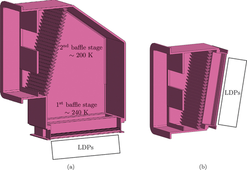
shows the MBA with classic, vertical mounting of the LDPs, which requires that the MBA include a 90-deg bend. We also investigate a second, optimized configuration, shown in , where the LDPs are mounted in an inclined fashion. This removes the 90-deg bend and reduces the overall length of the flow path, which both contribute to an increase in conductance. The important properties of both configurations are listed in . The transmission probability of both configurations was determined using the open-source, three-dimensional TPMC code MOLFLOW+.[Citation18] Particles were inserted at the MBA inlet based on a Maxwell-Boltzmann distribution function. It is noted that the simplified MBA configuration () leads to an increase in the transmission probability of about 6%.
TABLE II Properties of the MBA Subsystem for Two Investigated Configurations
III.B.3. Linear Diffusion Pumps
The LDPs are the high vacuum pumps installed in the INTL. Currently, three LDPs are considered to be installed in parallel per pumping port. The operating principle of diffusion pumps is based on the momentum transfer from a mercury vapor jet to the pumped gas. The mercury vapor jet is created by boiling mercury in an external boiler (e.g., using available process heat from the DIV cooling loop). The mercury vapor is then guided to the LDPs via a distribution system. Inside the LDP, one or multiple linear nozzle pipes are used to expand the mercury vapor into the pump body. The expansion through the nozzle creates a supersonic mercury vapor jet that is directed in the pumping direction. Gas molecules diffuse into the jet(s) (the eponymous process), and on average, receive a positive momentum in the pumping direction by means of intermolecular collisions with the vapor. At the outlet, a BP is connected to remove the gas. Thermalization of the mercury vapor is prevented by actively cooling the outer walls of the LDP in order to condense incident mercury vapor. Like many other high vacuum pumps, diffusion pumps feature gas-type dependent pumping speeds. The main reason lies in the mass dependence of the thermal gas velocities.
A two-dimensional DSMC model of these pumps was established in previous work (see Teichmann and Day[Citation19] and Teichmann, Giegerich, and Day[Citation20]). The most important gas species in the exhaust gas mixture were simulated in Teichmann and Day[Citation19], and relative differences in the order of magnitude of about 10% were found between and
. For this reason, individual simulations were performed for each of the four most abundant gas species in the exhaust gas mixture, namely,
and the hydrogen isotopologues
,
, and
. Two-dimensional DSMC simulations of a preliminary DEMO LDP design were performed under conditions estimated for the dwell and burn phases, respectively. An in-house modified version of the open-source code SPARTA[Citation21] was used to perform the DSMC simulations. Further details on the modifications are available in Teichmann, Giegerich, and Day.[Citation20] The actual performance of the three-dimensional pump was then estimated by simply scaling the two-dimensional results with the length of the LDP. The main properties and results are listed in .
TABLE III Properties and Performance of the LDP Subsystems Under Dwell- and Burn-Like Conditions with Respect to the Pumped Species
III.C. Hybrid Model
A loosely coupled hybrid model of the INTL high vacuum pumping system can be established by combining the subsystem simulation results using the Ansatz of Oatley as “mathematical glue.” Loosely coupled here means that the interaction between the subsystems is only considered in their mathematical combination using the Ansatz of Oatley and no feedback is interchanged between the simulations. Hybrid means that different calculation methods (TPMC and DSMC) are combined. Under the assumption of isothermal flow, the hybrid model prediction of the effective capture coefficient reads
where the transmission probabilities and the LDP capture coefficient
depend on the subsystem configurations (MFP, MBA) and operating states (LDP), respectively.
IV. RESULTS
IV.A. Summary
A core benefit of the loosely coupled hybrid model is that a change in any subsystem configuration and corresponding performance only influences said subsystem and none of the other subsystems. Thus, the number of computations reduces to the sum of all subsystem configurations, whereas a tightly coupled model would require the computing of all system configurations individually. Transferred to the configurations investigated in the present work, this corresponds to 14 subsystem configurations (four MFPs, two MBAs, and eight LDPs) that have to be computed using TPMC or DSMC, respectively, whereas the total of 64 system configurations () follows from the mathematical coupling [see EquationEq. (4)
(4)
(4) ] with only minimal additional computational effort. The total computational effort is therefore reduced by a factor of at least 4.6, and this efficiency gain is improved for an increasing number of subsystem configurations (as one would expect further along the subsystem design process).
The computed effective capture coefficients for all system configurations are collected in . Generally speaking, it can be seen that performance changes in the MBA (configurations a and b) and LDPs (depending on the gas type and operating phase) are dampened in the integrated system. The 6% improvement of the optimized MBA configuration b over the standard configuration a corresponds to an improvement of at most about 3% in the integrated system. The 8% difference between the LDP capture coefficients for and
is reduced to at most 2.5%. The dampening effect is amplified for system configurations that include MFP tubes with smaller diameters (configurations A and C). In order to identify the subsystems that bottleneck the integrated system, it is important to understand the relative sensitivities of the subsystems.
TABLE IV Effective Capture Coefficient of the INTL High Vacuum Pumping Train for Different Burn and Dwell Operating Conditions, Subsystem Configurations, and Pumped Gases
IV.B. Sensitivity Study
Due to the analytical coupling used to construct the hybrid model, it is possible to analyze the sensitivity of the system to its subsystems mathematically. Under the assumption that the layout of the system (i.e., the interfaces between subsystems) are fixed, which is reasonable as the space in the pumping ports is very limited, the transmission probabilities are the only determining factors. Therefore, the sensitivity of the system with respect to the property of subsystem
follows as the partial derivative, namely,
The relative sensitivity around a reference point 0, characterized by the respective system configuration given by MFP and MBA configurations and gas species, is obtained by normalizing the partial derivative [EquationEq. 5)(5)
(5) ] according to
The relative sensitivities for all eight configurations of MFP and MBA during burn and dwell for DT as the pumped gas are depicted in .
Fig. 4. Relative sensitivities of the subsystems on the effective system capture coefficient for DT during (a) burn and (b) dwell.
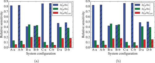
As the species-dependent capture coefficients of the LDPs (see ) are dampened in the integrated system (see ), the results can be considered representative for all gases in the exhaust mixture. The following discussion is equally true for burn () and dwell () as the subsystem sensitivities are nearly identical. Comparison of the relative sensitivities gives insight into the optimization potential of the individual subsystems.
For systems with MFP configurations A and C, which feature MFPs with smaller diameters, it is obvious that the system performance can basically only be improved by increasing the transmission probability (i.e., conductance) of the MFPs. The relative sensitivity of the subsystem containing the MFPs is more than five times higher than that of the other two subsystems in these configurations (A-a, A-b, C-a, and C-b), so that improvements of the other subsystems are practically nullified and are thus not worthwhile from an economic point of view. This is confirmed when comparing with MFP configurations B and D, which feature MFPs with larger diameters. In these cases the relative sensitivities of the subsystems are much closer, which implies that improvements of the subsystems can also have a significant impact on the integrated system.
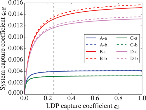
In all configurations, the LDP capture coefficient is the least sensitive, which explains the dampening of the species dependency in the effective system capture coefficient. However, this also implies that there is little optimization potential for the LDPs, as illustrated in more detail in . Even for the more favorable MFP configurations B and D (larger tubes), the effective system capture coefficient only changes by approximately 16% (B) and 14% (D), respectively, if a LDP capture coefficient of unity is assumed (which is a theoretical boundary case much above practically achievable values) and by approximately 10% (B) and 9% (D), respectively, when assuming .
Fig. 5. Effective system capture coefficient as a function of the LDP capture coefficient
for different system configurations.
It is emphasized here again that the previous considerations are only valid under the assumption of free molecular flow that is taken in the TPMC models and the application of the Ansatz of Oatley. As this assumption leads to conservative estimations of the performance, it is expected that the system performance will be improved in the transitional and viscous flow regimes and that the subsystem sensitivities will be more evenly distributed. With regard to the tokamak phases, this means that the earlier results should be considered realistic during dwell, but taken as lower limits during burn.
IV.C. Performance During Burn
During the tokamak burn phase, the DT fusion reaction is performed in the plasma in the torus. Both the DIRL and INTL pumping systems are active during this time. Within the existing uncertainties at the present design stage of EU-DEMO, an indication of the upper bounds of the throughput that has to be handled by the vacuum systems during burn are given in Day et al.[Citation4]. We assume the total throughput is about (
: at reference temperature 273.15 K) with a composition of
and
(mostly helium ash). Under the assumption of a DIR recycling efficiency of 80%, about
of pure
are separated by the MFPs. Therefore
have to be pumped by the INTL pumping system. Due to the extraction of pure
by the MFPs, the INTL composition changes to
and
.
Based on the throughput, the required effective pumping speed per port can be estimated according to
where is the number of assumed pumping ports,
(calculated from the reference value
at the expected DIV temperature of 570 K) and
[Citation3] is the assumed burn pressure in the sub-DIV region. It is emphasized here that there are still substantial uncertainties regarding the number of available pumping ports and the DIV performance, which is currently under reevaluation. The assumed values for
and
are examples to demonstrate the workflow, but might have to be revisited once more information on the DIV performance is known.
Now, the effective pumping speeds of the INTL pumping train can be estimated from the hybrid model results for the effective capture coefficient by means of EquationEq. (1)(1)
(1) . By inspection of EquationEq. (1)
(1)
(1) , it is clear that the pumping speed is proportional to
, where
is the molecular mass of the considered species. When assuming thermal equilibrium between the hydrogen isotopologues, the INTL gas mixture during burn is composed of about 48%
, 24%
and
, respectively, and 4%
(neglecting PEGs). For this reason, we estimate that assuming DT as the gas will give a good estimation for the entire mixture.
The effective pumping speeds for the different system configurations at 570 K are listed in . Based on the hybrid model results, all MFP configurations are capable of providing the required effective pumping speed (per port) of 6.3 m3 s−1. Configurations B () and D (
) include a comfortable safety factor in the range of 4 to 4.5. However, as stated before, the hybrid model is based on the assumption of free molecular flow. It therefore is likely that the actual pumping speeds would be higher during burn conditions, as the flow regime is in the transitional to viscous regime.
TABLE V Effective Pumping Speed
of the INTL High Vacuum Pumping Train for Different Subsystem Configurations During Dwell and Burn Phases at T = 570 K
IV.D. Performance During Dwell
Contrary to the burn phase, the dwell phase is transient. The torus is pumped down from burn conditions to the terminal dwell pressure. This pressure has to be significantly lower than the burn pressure in order to prepare for the next plasma ignition. For the MFPs, the most likely scenario is that they can support the INTL pumping system at the beginning of the pump-down phase. However, in order to provide a conservative estimation, we will assume that only the INTL pumping train is active during dwell. Similar to the considerations for the burn phase, we assume that the effective pumping speed of DT is a good estimate of the mixture pumping speed. The results of the hybrid model are given in .
The pump-down can then be described by the differential equation
where is the torus volume[Citation22] and
is the gas load during dwell. EquationEquation (8)
(8)
(8) can be integrated between the start/burn
and terminal
pressures to obtain an expression for the pump-down time
:
The pressures in the sub-DIV volume are assumed as and p1 = 2 × 10⁻³ Pa.[Citation3] We emphasize here that these are subject to change due to the uncertainties regarding the DIV performance. The gas load during dwell is comprised of two main sources: outgassing from the first wall and leakage into the torus. It is expected that the former will dominate the outgassing rate. Day et al.[Citation4] estimated an integral protium outgassing rate for tungsten of approximately 0.15 Pa m3 s−1 (at 573.15 K). However, as also noted by them, this does not include plasma-driven implantation and neutron damage, which are expected to alter the magnitude and composition of the outgassing gas over the lifetime of the machine. Therefore, it should be considered as a lower limit. Due to these uncertainties, we kept the outgassing rate as a free parameter and studied its influence on the pump-down time. The results for the different system configurations are depicted in .
Fig. 6. Dwell pump-down time as a function of the dwell gas load
for the different INTL system configurations.
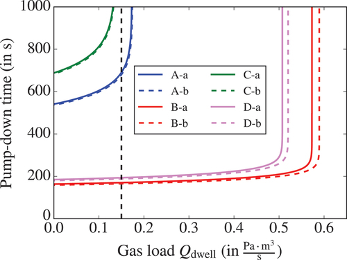
The targeted pump-down time of (see Day et al.[Citation4]) is only realistically achieved for system configurations B-{a,b} and D-{a,b}. Configurations C-{a,b} cannot meet the target time even in the unphysical limit of no gas load (
). While configurations A-{a,b} can meet the target pump-down time theoretically, this is only possible for outgassing rates significantly below the lower limit represented by the expected protium outgassing rate.
Furthermore, illustrates that there is a parameter window in which, after a critical outgassing rate is exceeded, it is impossible to pump down to the targeted terminal pressure even when relaxing the pump-down time requirement. This critical outgassing rate is found by solving EquationEq. (8)(8)
(8) in steady state (i.e., setting
). For the present system architectures, this limit lies at approximately 0.58 Pa m3 s−1 and 0.51 Pa m3 s−1 for MFP configurations B and D, respectively. It is therefore of vital importance that better estimations of the outgassing rate and the necessary terminal dwell pressure become available. Additionally, a different arrangement of the pumps may have to be considered (e.g., switching MFP and LDP positions) so as to provide a higher conductance, and by that, to move the operational constraints.
V. SUMMARY AND OUTLOOK
We introduced a hybrid model of the EU-DEMO INTL high vacuum pumping system. The hybrid model was developed based on the loose coupling of individual models of three subsystems: duct including MFPs, MBA, and LDPs. The coupling was achieved by applying the Ansatz of Oatley. While not expected to be as accurate as a direct simulation of the combined INTL high vacuum system, the presented hybrid model has distinct advantages, as illustrated. First, usage of individual simulation models for the subsystems allows for employing the most suitable method and tool for the individual subsystems, which enables more efficient parametric optimization of these systems. Second, coupling by the analytical Ansatz of Oatley creates the possibility of analyzing the sensitivities of the subsystem performances on the system performance mathematically. This gives insight into bottleneck subsystems, which have the highest optimization potential and optimization limitations.
In the present work, two different three-dimensional TPMC programs were used to simulate the transmission probabilities of the duct and baffle adapter, while two-dimensional DSMC was used to estimate the capture coefficient of the LDPs. Four different MFP configurations were compared. The impact of the inherent species-dependent performance of the LDPs on the effective system performance was analyzed. We found that the effective system performance was not very sensitive to the LDP performance in the configurations investigated.
The hybrid model was then exploited to predict the performance of the integrated INTL pumping system during the tokamak operating phases (burn and dwell) with respect to four different MFP configurations and two different MBA configurations. Comparing the effective pumping speed to the upper limits of the required pumping speed during burn, we found that all eight configurations performed as required (four even with a comfortable safety factor). Regarding the dwell phase, we used the model to estimate the pump-down time as a function of the gas load (assumed to be dominated by outgassing from the first wall). We found that the same four configurations can meet the required pump-down time. However, it was also found that the critical outgassing rate, above which the targeted terminal pressure cannot be reached, lies in the same order of magnitude as the expected protium outgassing rate alone.
The following points should be addressed in future research. It has to be tested if and how the DIV can be included in the hybrid model to extend the predictions from the sub-DIV volume to the actual plasma chamber. Additionally, the study can be extended by considering further exhaust gas mixture constituents (e.g., PEGs) once more reliable information on the expected amounts becomes available. Furthermore, the results of the loosely coupled hybrid model should, if possible, be compared to a full simulation of the INTL system. However, it is noted that this is currently not feasible because it would require a full three-dimensional DSMC model of the system, which cannot be computed in reasonable timescales even on up-to-date supercomputers, not to mention that the full model would have to reflect an existing three-dimensional design, which is not existing at the current concept design stage.
Ad interim, the approach shown in this paper serves to provide a helpful and consistent description to support design development. Regarding the performance during dwell, it is recommended to establish/improve the estimation of the outgassing rate and the terminal dwell pressure. Last, it is recommended to perform a broader study with a systematic variation of the pump arrangements to asses if the dwell performance can be improved.
Acknowledgments
Simulations were partially performed on the EUROfusion high-performance computer Marconi-Fusion. The authors gratefully acknowledge the resources allocated to projects VAC ND and LDP KIT. The authors would like to thank Ralf Müller for his help in preparing the CAD drawings.
Disclosure Statement
No potential conflict of interest was reported by the authors.
Additional information
Funding
Notes
a The abbreviation is used.
References
- C. DAY and T. GIEGERICH, “The Direct Internal Recycling Concept to Simplify the Fuel Cycle of a Fusion Power Plant,” Fusion Eng. Des., 88, 6–8, 616 (2013); https://doi.org/10.1016/j.fusengdes.2013.05.026.
- T. GIEGERICH and C. DAY, “The KALPUREX-Process—A New Vacuum Pumping Process for Exhaust Gases in Fusion Power Plants,” Fusion Eng. Des., 89, 7–8, 1476 (2014); https://doi.org/10.1016/j.fusengdes.2014.03.082.
- T. GIEGERICH et al., “Preliminary Configuration of the Torus Vacuum Pumping System Installed in the DEMO Lower Port,” Fusion Eng. Des., 146, B, 2180 (2019); https://doi.org/10.1016/j.fusengdes.2019.03.147.
- C. DAY et al., “The Pre-concept Design of the DEMO Tritium, Matter Injection and Vacuum Systems,” Fusion Eng. Des., 179, 113139 (2022); https://doi.org/10.1016/j.fusengdes.2022.113139.
- T. L. HO, “Speed, Speed Factor and Power Input of Different Designs of Diffusion Pumps, and Remarks on Measurements of Speed,” Physics, 2, 386 (1932); https://doi.org/10.1063/1.1745064.
- D. H. DAVIS, “Monte Carlo Calculation of Molecular Flow Rates Through a Cylindrical Elbow and Pipes of Other Shapes,” J. Appl. Phys., 31, 7, 1169 (1960); https://doi.org/10.1063/1.1735797.
- G. A. BIRD, Molecular Gas Dynamics and the Direct Simulation of Gas Flows, No. 42 in Oxford Engineering Science Series, Oxford University Press Inc. (1994).
- C. W. OATLEY, “The Flow of Gas Through Composite Systems at Very Low Pressures,” Br. J. Appl. Phys., 8, 1, 15 (1957); https://doi.org/10.1088/0508-3443/8/1/305.
- L. FÜSTÖSS and G. TÓTH, “The Problem of the Compounding of Transmission Probabilities for Composite Systems,” J. Vac. Sci. Technol., 9, 4, 1214 (1972); https://doi.org/10.1116/1.1317015.
- L. FÜSTÖSS and G. TÓTH, “The Resistance Concept and the Dynamical Characterization of Molecular Gas Flow,” Vacuum, 40, 1, 43 (1990); https://doi.org/10.1016/0042-207X(90)90115-F.
- K. JOUSTEN, “Molekulare Strömung von Gasen,” Chap. 8 in Handbuch Vakuumtechnik, 12th ed., K. JOUSTEN, Ed., pp. 171–193, Springer (2018).
- V. HAUER and C. DAY, “Conductance Modelling of ITER Vacuum Systems,” Fusion Eng. Des., 84, 2, 903 (2009); https://doi.org/10.1016/j.fusengdes.2008.12.115.
- D. A. KARPOV et al., “Vacuum Pumping System of TRT,” Plasma Phys. Rep., 47, 12, 1267 (2021); https://doi.org/10.1134/S1063780X21120023.
- B. J. PETERS and C. DAY, “Analysis of Low Pressure Hydrogen Separation from Fusion Exhaust Gases by the Means of Superpermeability,” Fusion Eng. Des., 124, 696 (2017); https://doi.org/10.1016/j.fusengdes.2017.05.124.
- B. J. PETERS, “Development of a Hydrogen-Selective Vacuum Pump on the Basis of Superpermeation,” PhD Thesis, Department of Mechanical Engineering, Karlsruhe Institute of Technology (2020).
- X. LUO and C. DAY, “3D Monte Carlo Vacuum Modeling of the Neutral Beam Injection System of ITER,” Fusion Eng. Des., 85, 7–9, 1446 (2010); https://doi.org/10.1016/j.fusengdes.2010.04.002.
- X. LUO et al., “Assessment of the JT-60SA Divertor Cryopump Performance,” Fusion Eng. Des., 136, 467 (2018); https://doi.org/10.1016/j.fusengdes.2018.02.099.
- R. KERSEVAN and J.-L. PONS, “Introduction to MOLFLOW+: New Graphical Processing Unit-Based Monte Carlo Code for Simulating Molecular Flows and for Calculating Angular Coefficients in the Compute Unified Device Architecture Environment,” J. Vac. Sci. Technol., A, 27, 4, 1017 (2009); https://doi.org/10.1116/1.3153280.
- T. TEICHMANN and C. DAY, “Particle Simulation of Linear Diffusion Pumps for DEMO Torus Exhaust Pumping,” Fusion Eng. Des., 169, 112694 (2021); https://doi.org/10.1016/j.fusengdes.2021.112694.
- T. TEICHMANN, T. GIEGERICH, and C. DAY, “Simulation of Mercury-Driven Diffusion Pumps for Torus Exhaust Pumping,” IEEE Trans. Plasma Sci., 50, 11, 4459 (2022); https://doi.org/10.1109/TPS.2022.3202083.
- S. J. PLIMPTON et al., “Direct Simulation Monte Carlo on Petaflop Supercomputers and Beyond,” Phys. Fluids, 31, 8, 086101 (2019); https://doi.org/10.1063/1.5108534.
- M. D’ONORIO and G. CARUSO, “Pressure Suppression System Influence on Vacuum Vessel Thermal-Hydraulics and on Source Term Mobilization During a Multiple First Wall–Blanket Pipe Break,” Fusion Eng. Des., 164, 112224 (2021); https://doi.org/10.1016/j.fusengdes.2020.112224.