
Abstract
In the field of decommissioning and decontamination, multiple difficulties arise. The main issues in tritium decontamination are due to its ability to permeate through virtually any material. As a result, the release of tritium from contaminated materials is affected by multiple parameters, complicating the exact characterization and choice of the decontamination strategy. Research efforts by the decontamination and clean-up processes group at SCK•CEN are currently concentrating on two different projects. In the first project, the dismantling of an obsolete tritium installation is evaluated. Parts of this installation have tritium inventories in the MBq/g range. Tritium release using several cutting techniques and the tritium inventory of the resulting cut parts and secondary materials, such as sawdust and cutting curls, is investigated. The second project concerns the detritiation and safe conversion of tritiated NaK into less reactive carbonates.
I. INTRODUCTION
In an experiment to test the feasibility of power ramping of individual fuel rods, a pressurized 3He tube was installed around a fuel bundle in the high neutron flux environment of the BR2 reactor. By varying the pressure, the neutron flux in the fuel bundle and the power generated in the bundle could be controlled. In this neutron capturing process, the 3He splits into 3H and 1H. To purify, measure, and control the pressure of the gas in the 3He tube, several appliances were foreseen in a glove box outside of the reactor core. The entirety of this installation was called the variable neutron shield (VNS). The VNS installation was taken out of use just before the turn of the century. Over the last years, the VNS has been dismantled piece by piece.[Citation1]
II. TRITIATED WASTE
The VNS installation consists of mainly stainless steel components, and can be split into two main parts: the installation outside the reactor and the gas tube around a fuel rod inside the reactor. This paper and recent decommissioning efforts only focus on the installation outside the reactor. The only activation products present in the installation outside the reactor originate from the sublimation of activation products in the bulk of the installation inside the reactor, which is negligible at pressures above 1 atm. The part of the installation outside the reactor can be divided further into the following subcategories, which are described in the following subsections.
II.A. Stainless Steel Pressure Circuit
As mentioned, the bulk of the installation is stainless steel. This stainless steel is mainly the tubing and pressure bellow responsible for pressure control in the gas cap and the ducts to the reactor and the glove box. The tritium inventory of these parts is expected to be in the kBq/g range.
II.B. Stainless Steel Glove Box Items
A number of pumps, samplers, and heating mantles were responsible for gas conditioning. These parts have a higher tritium inventory due to repeated heating and intensive use in tritium handling within the installation. These parts have an expected tritium inventory in the MBq/g range.
II.C. Titanium Getters
To filter out the hydrogen gas, several Ti getters were installed in the glove box. These getters have a high adsorption rate for hydrogen gas, so the 3He + HT gas mixture gets purified to 3He. The total tritium inventory in the five getters is 60 TBq (measured with calorimetry).[Citation2]
II.D. NaK Getter
In an effort to renew the glove box for the out-of-reactor installation, a NaK getter was used to capture the rest of the fraction of hydrogen molecules after the Ti getters. This getter was mildly tritiated with an unknown tritium inventory, which, with a 95% certainty, is not more than 500 MBq in 0.5 l liquid. The main issue with the NaK getter is its chemical reactivity.
III. DISMANTLING AND CHARACTERIZATION
As with all historical waste, characterization is the first obstacle in decommissioning. For this purpose, several items, such as furnace pumps, samplers, and heating mantles, were dismantled from the glove box. The Ti and NaK getters where extracted and evacuated. And last, the original pressurizing bellow, which was replaced due to a leak, was transported to the tritium lab after being stored for decades in a nuclear storage shed.
Several methods and iterations of characterization used to identify the contamination of the waste are discussed in the following subsections.
III.A. Calorimetric Characterization
The largest tritium inventory was expected in the titanium getter beds since their function was to alleviate and collect the tritium from the 3He gas.
Using a KEP Technologies calorimeter, the total tritium inventory of the five Ti getters was determined to be 60 TBq. However, the tritium inventory of the NaK getter allowed for only measurements around the detection limit. Using the calorimeter specifications and statistical analysis, we can say with a likelihood of 95% that the contamination will not be more than 500 MBq.[Citation2]
III.B. Surface Absorption in Relation to Known Samples
The reasoning for the parallel between the contamination of the VNS samples and the known contamination of the VNS furnace is based on two key foundations. First, a literature review indicated that the tritium sorption on the surface of metal is mainly located in the 15-μm-thick outer layer of the metal and decreases strongly toward the interlaying material.[Citation3,Citation4] Second, the diffusion and absorption of tritium depends on parameters such as temperature, pressure, and partial tritium pressure, as indicated by the literature.[Citation5] Since the exposure time and atmosphere were identical, a similar contamination per surface area is to be expected.
One of the furnace pumps installed in the VNS was documented to be detritiated with superheated steam. Smear tests before and after the detritiation determined that this procedure resulted in a decontamination factor (initial measured contamination/final measured contamination) of 9000. The activity of the condensed superheated steam was measured, and the total activity of the removed tritium was 0.65 GBq. Taking into account an elapsed time of 18 years and the half-life of tritium (12.26 years), an adjusted present-day value was calculated. The results from the detritiation experiment can be found in .Footnotea [Citation6]
TABLE I Results Detritiation Experiment 2004
III.C. Characterization Based on Surface Swipes
compares the removable surface contamination between the VNS sample from 18 years ago versus that of the samples taken out during the last decommissioning session in 2022.
TABLE II Smear Samples in Relation to Expected Value of Glovebox Items
The values of the first three pumps and the samplers of the 2022 samples agree with each other relatively well. These results are roughly 20-fold of the value of the outside smear test from . In the 2022 smear tests, the values of the mantles were significantly higher. The mantles were placed around the getters, heated, and subjected to strongly contaminated material. The logical reference is thus the value of the inside smear test from . Comparing these two, we see a similar (average) 20-fold contamination. The only deviating measurement was pump 4. Because of the general alignment, we assumed a contamination 20 times higher than the reference pump was representative.
The surfaces of the different bellow pieces were also wiped to determine the contamination. The results can be found in . It is important to note that the measurements in were taken on the outside of the items, while the measurements in were taken on the inside. These measurements indicate an average contamination of 61 kBq/dm2 based on geometry (given the weight and geometry, this translates to 70 kBq/g).
TABLE III Smear Samples Bellow
III.D. Characterization Based on Outgassing Measurements
The final way in which the VNS items were characterized was based on outgassing. The rate of outgassing is proportional to the contamination, as shown in the literature.[Citation7] Whether this proportionality relation is used per surface area to indicate the surface contamination per gram to indicate average contamination (a value more interesting for transport and disposal) is one and the same, as long as it is clear that the contamination is not uniform.
Looking at the outgassing of the VNS samples, we monitored the stack release of the lab in which the samples were handled. Averaging the measurements out over 3 weeks in which there was no other activity in the lab, we arrived at an average outgassing of just under 70 kBq/g/day. This corresponds to a contamination of 70 MBq/g, which is 17.5 times the contamination of the first estimate based on the 2004 detritiation test. These results strengthened the conclusion that the samples taken in 2022 were approximately 20 times more contaminated than the furnace pump dismantled in 2004.
To measure the outgassing of the pressurizing bellow, and thus estimate contamination in a similar fashion, compressed air was forced through the bellow and the bellow was actuated several times. After this, the compressed air was forced through the leak in the inner bellow. The outgassing varied from 350 kBq/g/day in pulsating turbulent air to just under 27 Bq/g/day in steady flow. This corresponds to a contamination of 30 to 400 kBq/g. It is unclear whether the more turbulent air on the surface of the contaminated material had an effect on the relationship between outgassing and surface contamination or the possibility of dust mobilization. Due to this uncertainty, the bellow was estimated to have a tritium inventory on the order of a maximum of 100 kBq/g. This estimation was based on both the swipes and steady-state outgassing.
IV. TRITIUM TRANSFER WHILE SCRAPPING
To gain experience in dealing with the risks of scrapping tritium-contaminated material, several cutting techniques were monitored in a controlled environment. The tritium was monitored locally on the working height and as room monitoring. Each of these techniques had a distinct pattern of tritium release originating from the same material. The following subsections discuss the monitored tritium release per cutting technique.
IV.A. Pneumatic Pipe Cutter
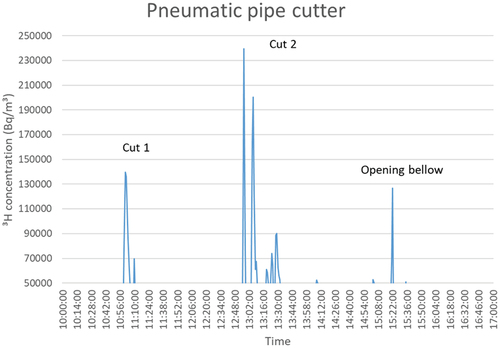
The pneumatic pipe cutter is a cutting technique often used to dismantle large pipes and ducts. Its release pattern is the most straightforward since it starts with the contaminated surface layer and ends with a contaminated surface layer. In this regard, the release was completely in line with the literature concerning the depth profile of the tritium inventory and provided relatively large peaks at the start of the cutting and the end of the cutting.[Citation3,Citation4] The peaks reached 230 kBq/m3 with a background signal of 20 ± 10 kBq/m3, as is visible in in which cut 1 represents the top part of the bellow and cut 2 the bottom part, near the seal.
Fig. 1. Tritium release using the pneumatic pipe cutter.
IV.B. Milling Machine
Similar to the previous cutting technique, the milling machine starts with the surface where most of the contamination is located. However, the tritium release was not in line with the pipe cutter. The milling machine did not agitate the steel to the extent that large peaks in the release were visible. The tritium release was relatively constant, just reaching above the background signal but not exceeding 50 kBq/m3. The released particles had a thickness of ≈0.05 mm and an area of ≤0.5 mm2.
IV.C. Pot Drill
This scrapping technique had the lowest tritium release of all the tested techniques. The tritium release during pot drilling did not notably exceed the background signal, but did produce large amounts of metal chippings and was very time consuming.
IV.D. Bandsaw
The bandsaw was probably the most time-efficient method of scrapping metal. The main drawback was overheating, which occurred when cutting very thick–walled samples. During this overheating, slightly larger releases of tritium were noticeable, up to 70 kBq/m3. To prevent this, cutting was spaced in small intervals to allow for cooling. No active cooling was implemented during cutting (to minimize spreading, which could impact measuring accuracy). During normal operation of the bandsaw, tritium release did not exceed the background signal.
IV.E. Dust Spreading
The spread of dust and the risk of contamination were also considered in this study. Every cutting technique produced its own distinct form of chips. The ease of containment of the chips and the degree to which these chips were contaminated gave further motivation in the choice of the best cutting technique for scrapping. The gathered chips will be analyzed in the material detritiation facility from the UK Atomic Energy Authority.
V. TRITIUM RELEASE IN NaK
To be able to safely handle the chemically active NaK in an easy, accessible manner, the tritium content must be removed as much as possible. While setting up the process to remove tritium, the dependency and sensitivity of the release in relation to several parameters were tested. By better knowing the behavior of tritium in NaK, optimal working conditions could be determined for the detritiation. The following subsections discuss the dependencies and difficulties in testing.
V.A. Dependency on Tested Parameters
The tests were performed by bubbling nitrogen through heated NaK. To regulate the fraction of tritium/hydrogen (T/H) in the mixture after the getter, hytec 2 (2% H2 in Ar) was added. The resulting mixture passed a CuO catalytic converter and a molecular sieve.
To determine the working conditions for the best detritiation, tritium release, as a result of nitrogen flow, was tested first. Theory would suggest a flow as high as possible, but to avoid a NaK spill, the nitrogen flow was not increased above 2 l/min, and with this, the first of the ideal working parameters was set. The results were initially as expected. The ramp up in tritium release behaved linearly to the increase in flow.[Citation8] However, this expected behavior did not reach a steady state.
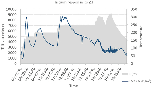
The temperature dependency was exponential to the increase in temperature, as theory would suggest, with a slight increase in tritium release below 175°C and a significant ramp up above. This dependency was tested to a temperature of 400°C. However, this expected behavior also did not reach a steady state. For each ramp in temperature, the tritium release peaked, but quickly reverted back to a lower release. Because of this reaction, it was suggested that the release might be dependent on a change in temperature rather than absolute temperature. By oscillating the temperature and monitoring the tritium release, this was proven untrue (). It seemed the liquid-metal roster had more accessible paths for the N2 to pass. After long diffusion times, the tritium response was replicable.
Fig. 2. Tritium response to changing temperatures.
Throughout all of the tests, a significant amount of tritium was captured in the molecular sieves at the end of the installation. The addition of hytec 2 proved to be unnecessary, and the capture rate was over 99.5%. With this, the last parameter was set and the ideal working conditions were determined to be a gas flow bubbling through the NaK of 2 l/min N2 and a working temperature of 400°C.
Because of the long diffusion times and diminishing returns (i.e., the necessary diffusion time for replicability increased after each test), the tests were stopped. The experiment took 12 days of active testing, with (at the end of the experiment) almost 5 days of diffusion time between the testing days. Another key reason to stop the tests was the several instances of oxidation and NaK overflow/spill. At the end of this process, the total activity of the removed tritium was approximately 20 GBq, a long shot from the statistically determined possible inventory of 500 GBq.
V.B. Further Treatment
Since the tritium inventory could not be reduced, the next step was to tackle the chemical reactivity. The process to transform the metallic NaK to ionic form was based on two exothermic reactions: oxidation and carbonatation. Both can be controlled by changing the respective O2 and CO2 flow through a fluidized bed of Na·Na2CO3/K·Na2CO3. The produced heat was dissipated through thermal oil around the bed. These reactions have been proven to work without H2 production, and had a 99% conversion rate. The exhaust gas passed through the detritiation module (tritium monitor + catalytic converter + molecular sieve + tritium monitor). Samples of the soluble carbonate were dissolved in a liquid scintillation cocktail to assess the tritium content.[Citation9]
VI. CONCLUSIONS
We compared multiple techniques for dismantling tritium-contaminated installations, each with distinct advantages and disadvantages in terms of tritium release, dust production, and ease of containment and applicability. We could not point to one of the techniques as best or recommended. Instead, the best technique must be judged on an individual case-by-case basis. For the detritiation of NaK, we found that we can confirm the theoretical dependencies of release to a certain extent. However, the diffusion time necessary to replicate the results makes the detritiation of NaK a time-consuming process regardless of working conditions. It must be weighed to determine to what extent the allocation resources are worth the diminishing reduction in contamination.
Disclosure Statement
No potential conflict of interest was reported by the authors.
Additional information
Funding
Notes
a Smear tests were performed with 1 ml of demineralized water over a surface of 4 dm² and measured in a cocktail with ProSafe LT+.
References
- K. DYLST et al., “Present and Future Tritium Waste and Decommissioning Challenges at SCK•CEN,” presented at the 18th Tritium Users Group, Gretna Green, United Kingdom (2019).
- K. DYLST, H. LODEWYCKX, and Y. D’JOOS, “Dismantling an Obsolete Tritium Installation,” presented at EnergEn 2018, Govora Băile, Romania (2018).
- T. HIRABAYASHI et al., “Sorption of Tritium on Surface-Modified Type-316 Stainless Steel,” Fusion Eng. Des., 10, 287 (1989); http://dx.doi.org/10.1016/0920-3796(89)90065-3.
- A. PEREVEZENTSEV et al., “Contamination of Stainless Steel Type 316 by Tritium,” Fusion Sci. Technol., 41, 746 (2002); http://dx.doi.org/10.13182/FST02-A22686.
- G. J. THOMAS and R. D. SISSON, “Tritium and Helium-3 Release from 304L and 21-6-9 Stainless Steels,” Proc. Fusion and Isotopic Applications, National Topical Meeting (1980).
- J. BRAET et al., “Characterisation of JET Waste Streams (Organic Liquids, Soft Housekeeping Waste, Contaminated Metals) and Application of Detritiation Techniques: Final Report,” Final Report of Task JW3-FT-2.15, SCK•CEN Report, R-3939, Mol (Sep. 2004).
- A. B. ANTONIAZZI, W. T. SHMAYDA, and T. PALMA, “Correlation of Tritium Outgassing from Metal Surfaces with Surface Smearing,” presented at the 15th IEEE/NPSS Symp. Fusion Engineering (1993).
- J. REIMANN, R. KIRCHNER, and D. RACKEL, “Tritium Recovery from NaK-Cold Traps: Investigation of Hydrogen Release Kineticzs,” Fusion Eng. Des., 18, 67 (1991); http://dx.doi.org/10.1016/0920-3796(91)90109-4.
- J. BRAET et al., “Development of a Safe Technology for the Treatment of Sodium Waste: Early Experience. Waste Management,” Waste Management 2008 Proc. (Vol. 1), Phoenix, Arizona (2008).