
 ?Mathematical formulae have been encoded as MathML and are displayed in this HTML version using MathJax in order to improve their display. Uncheck the box to turn MathJax off. This feature requires Javascript. Click on a formula to zoom.
Abstract
Insulated sandwich panel consists of face layers separated by foam insulation cores. Existing studies are mainly focused on two-layers sandwich panel. Multiple layers can also be used to increase the panels’ strength and improve their energy performance. This article presents an analytical solution for multi-layers insulated sandwich panels with flexible shear connectors, such as Fiber-Reinforced Polymer (FRP) shear connectors. For flexible shear connectors, the slip between layers leads to partial Degree of Composite Action (DCA), which is considered in the analytical solution. The analytical results are verified with Finite Element (FE) analyses. Finally, a multi-layers sandwich panel application is presented.
1. Introduction
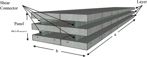
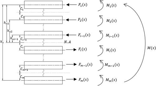
Insulated sandwich panels are increasingly used in structural applications such as residential houses, schools, etc. Most of the existing studies are focused on two-layers sandwich panels, where the layers are separated by a nonstructural foam insulation core. Typically, the layers have the same width and thickness and are made of the same material. Other than two-layers insulated sandwich panels, multiple layers can also be used, as shown in , which can increase the thermal performance, spanning, corrosion resistance, and strength compared with the two-layers panels [Citation1,Citation2]. In civil structural applications, precast sandwich panel typically consists of two- or three-layers enclosing insulation cores. Layers can sometimes referred to as wythes [Citation1,Citation2], however, to generalize the application of this study, the term “layer” will be used throughout the article.
Figure 1. Multi-Layers Insulated Sandwich Panel with Shear Connectors (Insulated cores are removed for illustration purpose).
Development of multi-layers sandwich structures started a long time ago. Carrera conducted a historical review on the interlaminar continuity of transverse stress at each layer, which was called Zig-Zag theories for multi-layers plates [Citation3]. The review presented the development of Zig-Zag theory, which was first proposed in 1935 by Lekhnitskii. From then, further research was followed, including the Carrera unified formulation (CUF) [Citation4]. Recent development of sandwich structures, including multi-layers plates, was discussed in ref. [Citation5] and [Citation6]. Recent research on multi-layers structures was focused on developing Finite Element Method [Citation7,Citation8]. An analytical formulation was proposed for damped free vibration and frequency response analysis of composite plates with embedded viscoelastic layers considering lamination schemes and layers, aspect ratios [Citation9]. However, the aforementioned literature was mainly targeting multi-layers structures consisting of several layers attached together. To the best of the authors’ knowledge, limited research is available to study the effect of shear connectors with variable stiffness on multi-layers sandwich panels.
Different types of connectors have been used to connect the layers. Recently, Fiber-Reinforced Polymer (FRP) shear connectors have been used for sandwich panels because of their many advantages, such as lower weight-to-strength ratio, high strength, and non-corrosive properties [Citation10]. Since FRP connectors have lower stiffness and are flexible, the slip between the layers cannot be neglected. This will lead to partial Degree of Composite Action (DCA). Many studies have been carried out on this topic [Citation11–13]. Yossef and Chen [Citation10] derived an analytical model on effective width of two-layers sandwich panel considering partial DCA. High-order closed solution for multi-layers sandwich panels has been developed by Thomsen [Citation14] taking into consideration the interface cores between the layers. However, the study did not include the effect of flexible shear connectors. This article aims to predict the stress and deflection of multi-layers sandwich panels with flexible shear connectors considering partial DCA. The analytical results will be verified against those from Finite Element (FE) analyses, and then the analytical model will be used to study multi-layers sandwich panels.
2. Analytical model
The analytical model is based on the following assumptions:
Materials are linear elastic, and shear connectors have the same material properties.
There is no torsion as the plate-sections are symmetric.
The shear deformation is caused by the flexible shear connectors only.
Thin plate theories can be applied to the layers.
The insulation cores are neglected.
All shear connectors have the same stiffness.
Based on Classical Lamination Theory (CLT) and the assumptions, Yossef and Chen [Citation10] defined axial force Nx (x,y) based on an amplitude function Nj(y) as:
(1)
(1)
where C1j and C2j are the constants that can be obtained from the boundary and loading conditions, y is the width of the layer, j is the summation index, and
can be defined as:
(2)
(2)
where a is the span of the panel, and v is Poisson’s ratio.
2.1. Boundary conditions
Each plate-section has different boundary conditions at the two edges that can be defined through C1j and C2j. In this section, we consider four types of thin-walled composite plate-sections, which cover common configurations of the shear connectors, namely, single box section with two shear connectors, WF sections with inner symmetric plate-section, cantilever, and multiple shear connectors.
2.2. Single box section
In a single box section, the shear connectors are at edges only, as shown in . Based on EquationEquation (1)(1)
(1) , the axial force
and the shear force Nxy for a typical layer are:
(3)
(3)
(4)
(4)
Figure 2. Box plate-section with shear connectors for multi-layers sandwich panel.
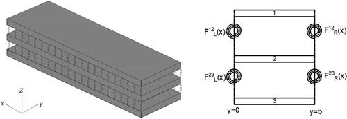
Based on the boundary conditions at y = 0 and y = b as shown in , we have:
(5)
(5)
(6)
(6)
where F(x) is the force transferred through the shear connector, ηr and ηl are shear flow distribution factors at the right and left sides of the section, respectively. The shear flow starts from the mid-point of the upper layer and goes through the shear connectors to the mid-point of the second layer until it reaches the mid-point of the mth layer. Shear flow distribution factors can be assumed to be 1 for single box sections. Based on EquationEquations (5)
(5)
(5) and Equation(6)
(6)
(6) , F(x) can be expressed as:
(7)
(7)
(8)
(8)
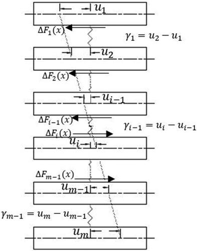
Slip between layers is defined as the change in force “ΔF(x)” per stiffness of shear connectors “K”, as shown:
(9)
(9)
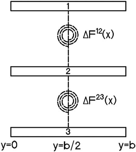
Since the slip is the differences between the horizontal displacements of the layers as shown in , it can be described for multi-layers sandwich panel in a general form as:
(10)
(10)
(11)
(11)
Figure 3. Slip between layers.
Combining EquationEquations (9)(9)
(9) and Equation(11)
(11)
(11) , we have:
(12)
(12)
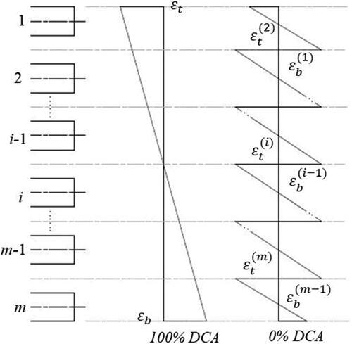
where
are top and bottom strains for each layer, as shown in . They can be calculated at the neutral axis between two-layers. In a plate-section, the strain in each layer is caused by a combination of bending moment and axial force. Assuming both layers are above the neutral axis, the strain can be calculated as:
(13)
(13)
(14)
(14)
where
for isotropic materials, such as concrete and steel. κi is the i-layer curvature, as defined in EquationEquation (16)
(16)
(16) . Plugging EquationEquations (13)
(13)
(13) and Equation(14)
(14)
(14) into EquationEq. (12)
(12)
(12) , we have:
(15)
(15)
Figure 4. Strain distribution.
The assumption that the layers will deflect an equal amount of moment indicates that the angle changes along the length be equal, then we have:
(16)
(16)
where
are moment, distance between mid-depth of the layer to the neutral axis between two-layers, width of the sandwich panel, number of layers, and flexural rigidity, respectively. Based on the equilibrium of the moment for a multi-layers sandwich panel shown in , we have:
(17)
(17)
where
and
represent the number of shear connectors for the entire section and shear force for i-layer, respectively, which can be defined as:
(18)
(18)
Figure 5. Axial and bending moment on multi-layers sandwich panel.
Substituting EquationEquation (17)(17)
(17) into (Equation16
(16)
(16) ), we have:
(19)
(19)
where
represent the distance from the center of the i-layer to the neutral axis of the sandwich panel and the distance from the center of the upper layer to the center of the lower layer, respectively.
Substituting EquationEquation (19)(19)
(19) into (Equation15
(15)
(15) ), we get:
(20)
(20)
where S is the spacing between layers. Combining EquationEquations (12)
(12)
(12) and Equation(20)
(20)
(20) , we have:
(21)
(21)
where
and
is the shear force distribution factor that counts for the share of the total shear force for the ith layer, which can be obtained based on the first moment of area:
(22)
(22)
EquationEquation (21)(21)
(21) can be expanded to a general closed-form equation:
(23)
(23)
In case of three-layers, axial and shear forces in the upper layer can be assumed to be equal to axial and shear forces in the lower layer with different directions, i.e., -
and axial forces in the middle layer located at neutral axis equal zero. Therefore, in the 3-layers panel,
and shear force distribution factor can be obtained for the upper and lower layers,
Therefore, EquationEquation (23)
(23)
(23) can be reduced to:
(24)
(24)
In order to solve EquationEquation (24)(24)
(24) , Yossef and Chen [Citation10] expressed the moment as:
(25)
(25)
where
(26)
(26)
Using EquationEquations (3)(3)
(3) , Equation(7)
(7)
(7) , Equation(8)
(8)
(8) , and Equation(25)
(25)
(25) into EquationEq. (24)
(24)
(24) , the partial differential EquationEquation (24)
(24)
(24) is solved using Fourier series, similar to the solution for two-layers sandwich panels [Citation10]. Extending this solution to multi-layers sandwich panels with the same thickness and material properties and solving for
and
we have:
(27)
(27)
where
Solving more than 3-layers requires solving each connector above the centerline, since it is assumed that the sandwich panel is symmetric about the neutral axis. EquationEquation (23)(23)
(23) can be applied to the upper connectors only, which yields two equations instead of one for 4- and 5-layers. More equations are required for more layers. For illustration purpose, the solutions for 4- and 5-layers sandwich panels are presented in this article.
For 4-layers sandwich panel, Therefore, EquationEquation (23)
(23)
(23) yields:
(28)
(28)
(29)
(29)
For 5-layers sandwich panel, as shown in . Thus, EquationEquation (23)
(23)
(23) yields:
(30)
(30)
(31)
(31)
Figure 6. Shear force distribution on 5-layers sandwich panel (a) side view, (b) plate-section, (c) typical shear force diagram.
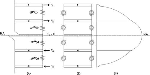
It can be noted from the above equations that shear force distribution factors for 4-layers sandwich panel are whereas for 5-layers sandwich panel
It is worth noting that, in case of odd number layers such as 3 and 5, the distribution factor for the middle layer should be slightly higher than the distribution factor for adjacent layers. However, the axial and shear forces in the middle layer can be assumed to be zero, which indicates that the multiplication of both equals zero. Therefore, the distribution factors for middle layers do not need to be considered.
It should be noted that each equation yields two unknowns for single box sections, as shown in EquationEquation (27)
(27)
(27) . Therefore, for two equations for single box section, the number of unknowns
should be four.
for 4 and 5-layers sandwich panels can be solved using similar procedure in EquationEquation (27)
(27)
(27) .
2.3. Wide flange (WF) section
WF is a panel that has one shear connector in the middle, as shown in . Thus, only one unknown (C1j) exists for 3-layers sandwich panel. Yossef and Chen [Citation10] derived equations for 2-layers WF and cantilever sandwich panels based on single box boundary condition. Equations from (32) to (38) are derived following the same approach, while considering multi-layer factors discussed in Section 2.2. Therefore, for 3-layers sandwich panel with WF section, EquationEquation (24)(24)
(24) can be rewritten as:
(32)
(32)
Figure 7. WF section.
Similar to single box section, we can obtain:
(33)
(33)
where
(34)
(34)
C1j and C3j can be solved for 4-layers and 5-layers sandwich panels, respectively.
2.4. Cantilever section
Similar to EquationEquation (23)(23)
(23) , forces in the cantilever section can be formulated as:
(35)
(35)
where
can be expressed as:
(36)
(36)
Solving for at y = 0, we get:
(37)
(37)
where
is the shear flow distribution factor for cantilever section.
(38)
(38)
Similarly, solutions for 4-layers and 5-layers sandwich panels can be obtained by substituting EquationEquations (36)(36)
(36) and Equation(25)
(25)
(25) into EquationEq. (35)
(35)
(35) at ΔF12 and ΔF23, with similar shear distribution factors discussed earlier at the single box section.
2.5. Multi-cell box section
The general solution is still useable for multi-shear connectors. However, the distribution of shear flow is not equal between shear connectors. For example, the shear flow distribution factor for the inner shear connectors can be divided into two distribution factors, where the summation of the two to be one. However, for the edge shear connector, the distribution factor is equal to one, as shown in .
Figure 8. Multi-cell box section [Citation10].
![Figure 8. Multi-cell box section [Citation10].](/cms/asset/c2ac73f2-20df-4af1-a3c4-b117c3df2b12/umcm_a_1998736_f0008_b.jpg)
Yossef and Chen [Citation10] developed two equations to obtain the distribution factors at the shear connector positions. One equation can be obtained from the summation of shear distribution factors at any shear connector as:
(39)
(39)
where
is the distribution factor for the cell (i-1) on the left side and
is the distribution factor for cell (i) on the right. The other equation can be obtained based on the continuity of the stress over the plate-section as:
(40)
(40)
It should be noted that the values of distribution factor for the shear flow depend on the stiffness of the shear connector. F(x) can be obtained by:
(41)
(41)
where
and
can be obtained by Equation (46).
2.6. Degree of composite action
Since FRP connectors are flexible and the slip between the layers cannot be neglected, this will lead to partial degree of composite action. Lorenz and Stockwell [Citation15] defined the DCA, which was used in the American Institute of Steel Construction [Citation16]. We can extend the concept to the multi-layers sandwich panel:
(42)
(42)
3. Validation using finite element model
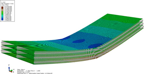
Yossef and Chen [Citation10] constructed FE models for 2-layers sandwich panel using ABAQUS to validate their analytical model with experimental results. In this article, we use extend the same FE model to validate the analytical model of 3-, 4- and 5-layers sandwich panels, as shown in . The layers are 76.2 mm thick, 3657 mm wide, 7049 mm long, and are separated by 102 mm thick foam cores. The layers are connected with shear connectors, where the spacing between the shear connectors is 1219 mm. Young’s modulus and Poisson’s ratio for concrete are 29,322 MPa and 0.15, respectively. A point load of 44,482 N is applied above the shear connector. The layers are modeled using shell element (S4R) and are connected using CONN3D elements (Cartesian, Cardan) which are rigid except for the stiffness in the y-direction. The mesh size used is 50.8 mm by 50.8 mm for cantilever section, while for single box and WF, the mesh size used is 12.19 mm by 7.05 mm based on a convergence study. The boundary conditions are set to be roller on one side and pin on the other side.
Figure 9. FE model for 4-layers 2-cell sandwich panel.
The analytical model is used to calculate the stiffness (K) for different degrees of composite (25%, 50%, 75%, and 100%). The stiffness values in the analytical model are assumed to be continuous, but in the FE model, they are concentrated at each node. Therefore, the stiffness in the FE model can be expressed as:
(43)
(43)
where a and n are the span and number of connectors per one row of the sandwich panel, respectively. The stiffness values are shown in for different configurations of shear connectors.
Table 1. Shear connector stiffness for single box.
Table 2. Shear connector stiffness for WF.
Table 3. Shear connector stiffness for cantilever.
Table 4. Shear connector stiffness for 2-cell.
The results, as shown in and , prove that the analytical model can accurately predict the behavior of multi-layers sandwich panels in terms of stress considering different DCAs. Results are calculated and exported for the stress of the upper layers near mid-span at 3,383mm from one side to avoid stress concentration due to loading. The results presented in the figures show one-half of the span, since the other span is mirrored due to symmetry. show the shear forces in 4-layers, 2-cell sandwich panel for 25%, 50%, 75%, and 100% DCAs, respectively. These values are displayed using ABAQUS output parameter (CEF), which refers to connector elastic force. The results show that the shear force values are high at the end of the panels and almost vanishes at the mid-span. It can be also noted that the forces vary along the thickness, where the middle connector takes the largest force, the same as observed from the analytical section. shows that for 2-cell sandwich panel at 100% DCA, the inner connectors take more forces than the external ones.
Figure 10. Stress distribution for 3-layers (single box).
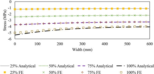
Figure 11. Stress distribution for 3-layers (WF).
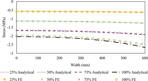
Figure 12. Stress distribution for 3-Layers (Cantilever).
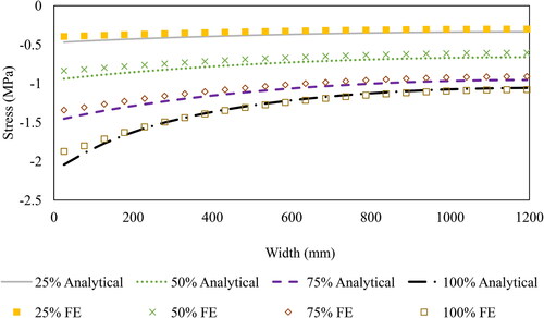
Figure 13. Stress distribution for 3-layers (2-Cell).
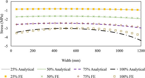
Figure 14. Connector shear forces for 4-layers (2-cell) with different DCA: (a) 100%, (b) 75%, (c) 50% and (d) 25%.
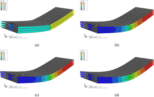
Figure 15. Connector shear forces for 4-layers (2-cell) with 100% DCA (Layer elements are not shown for clarity).
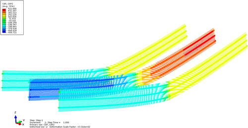
Table 5. Average stress for single box (MPa).
Table 6. Average stress for WF (MPa).
Table 7. Average stress for cantilever (MPa).
Table 8. Average stress for 2-cell (MPa).
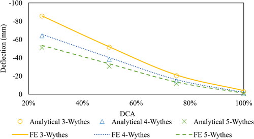
Deflection of panels with different configuration of layers versus DCA is shown in . The result show that the analytical model can accurately predict the behavior of multi-layers sandwich panels for 2-cell configuration. Typical results are also obtained for other configurations.
Figure 16. Mid-span deflection of 2-cell for multi-layers configurations.
4. Application
In this section, the analytical model is used to study the behavior of different multi-layers concrete insulated sandwich panels with CFRP shear connector mesh. FE analysis is also conducted for the same sandwich panels to obtain the stiffness of the shear connectors. The study can be divided into three steps as the following:
Step I: Preparing the Geometry of Multi-layers Sandwich Panel
In order to analyze the behavior of multi-layers sandwich panel and evaluate the effect of the number of layers on stress and deflection, we use the same total thickness of the sandwich panel, but with different number of layers. The thickness of the layers and insulation cores are distributed evenly over the total thickness, as shown in and .
Figure 17. Geometry of multi-layers.
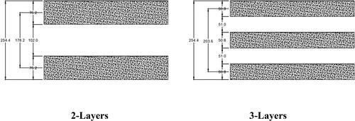
Table 9. Geometry of different number of layers.
Step II: Modeling the CFRP and obtaining the shear connector stiffness
Assuming that the same shear connector is used, the stiffness of the shear connectors in the sandwich panel is dependent on their height, i.e., the thickness between the layers. Hence, we construct three different FE models for two-layers sandwich panels with CFRP shear connector and WF section using ABAQUS to evaluate the stiffness of CFRP per length. The layers are 76.2 mm thickness, 1,219 mm wide, 7,049 mm long, and are separated by 102 mm, 51 mm, and 34 mm thick cores. The material properties of concrete and CFRP are modeled as linear elastic as shown in . The concrete layers and CFRP are modeled using solid element (C3D8R) and wire truss (T3D2), respectively. The CFRP shear connectors are connected to concrete layers using TIE constraints and have a spacing of 46 mm and area of 41 mm2/m in the longitudinal direction; and a spacing of 41 mm and area of 45.4 mm2/m in the transverse direction, as shown in . The bottom layer is fixed while the top layer is subjected to a pressure of 4.788 × 10⁻³ N/mm2, as shown in . It should be noted that average displacement is per span (a). Then, the stiffness for the analytical model can be calculated using the following equation:
(44)
(44)
Figure 18. Pressure load applied.
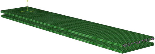
Figure 19. CFRP geometry.
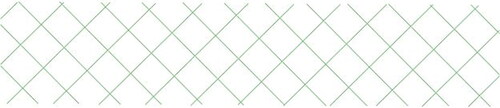
Table 10. Material properties.
Step III: Using the Stiffness in the Analytical model
Stiffness values in are used in the derived analytical model to obtain the deflection, stress, and DCA for each case and compared with FE results. The same FE model is used, with load set to be 44.482 kN going downwards and placed in the mid-span above the connector. The boundary conditions are set to be simply supported. Results from show good correlation between the analytical and FE models. The results also show that DCA increases with the increase of the number of layers per fixed panel depth. and show that the deflection and stress decrease with the increase of the number of layers per constant sandwich panel depth. Therefore, it can be concluded that increasing the number of layers will make the sandwich panel behave closer to the rigid panel with 100% DCA.
Figure 20. Deflection of multi-layers with CFRP shear connector.
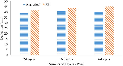
Figure 21. Stress on top surface of multi-layers with CFRP shear connector.
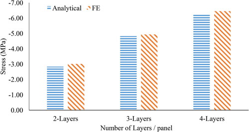
Table 11. Shear stiffness of multi-layers sandwich panels.
Table 12. Deflection and stress results of multi-layers with CFRP.
5. Conclusions
This article presents an analytical model for analyzing multi-layers sandwich panels with flexible shear connectors considering partial DCA. Based on this study, the following conclusions can be drawn:
The analytical model can accurately predict the behavior of multi-layers sandwich panels with different DCAs, in terms of both stress and deflection.
The analytical model can be used for different configurations of shear connectors, including single box, wide flange, cantilever, and multi-cell sections.
The number of the layers can significantly affect the behavior of the sandwich panel.
Increasing the number of layers for the sandwich panel with the same total panel thickness will reduce the stress and deflection and increase the strength of the sandwich panel, due to the increase of the DCA.
Acknowledgments
The first author gratefully acknowledges the National Natural Science Foundation of China (52078032), the Science and Technology Foundation of Beijing Jiaotong University (2019RC102), and Shandong High Speed Railway Construction Equipment Co., Ltd. for the support. The second author would like to thank University of Jeddah, Saudi Arabia, for financial support. The third author would like to thank Aalto University Foundation for the grant towards postdoctoral researcher position. The authors thank Dr. In Ho Cho from Iowa State University for his review.
References
- B. J. Lee, and S. Pessiki, Thermal performance evaluation of precast concrete three-wythe sandwich wall panels, Energy Build., vol. 38, no. 8, pp. 1006–1014, 2006. DOI: 10.1016/j.enbuild.2005.11.014.
- B.-J. Lee, and S. Pessiki, Design and analysis of precast, prestressed concrete, three-wythe sandwich wall panels, PCIJ., vol. 52, no. 4, pp. 70–83, 2007. DOI: 10.15554/pcij.07012007.70.83.
- E. Carrera, Historical review of Zig-Zag theories for multilayered plates and shells, Appl. Mech. Rev., vol. 56, no. 3, pp. 287–308, 2003. DOI: 10.1115/1.1557614.
- E. Carrera, Theories and Finite Elements for Multilayered Plates and Shells: A Unified Compact Formulation with Numerical Assessment and Benchmarking, Arco., vol. 10, no. 3, pp. 215–296, 2003. DOI: 10.1007/BF02736224.
- V. Birman, and G. A. Kardomateas, Review of current trends in research and applications of sandwich structures, Compos. Part B Eng., vol. 142, pp. 221–240, 2018. DOI: 10.1016/j.compositesb.2018.01.027.
- A. S. Sayyad, and Y. M. Ghugal, Bending, buckling and free vibration of laminated composite and sandwich beams: A critical review of literature, Compos. Struct., vol. 171, pp. 486–504, 2017. DOI: 10.1016/j.compstruct.2017.03.053.
- A. Pagani, S. Valvano, and E. Carrera, Analysis of laminated composites and sandwich structures by variable-kinematic MITC9 plate elements, J. Sandwich Struct. Mater., vol. 20, no. 1, pp. 4–41, 2018. DOI: 10.1177/1099636216650988.
- A. Alaimo, C. Orlando, and S. Valvano, An alternative approach for modal analysis of stiffened thin-walled structures with advanced plate elements, Eur. J. Mech. A/Solids., vol. 77, pp. 103820, 2019. DOI: 10.1016/j.euromechsol.2019.103820.
- A. Alaimo, C. Orlando, and S. Valvano, Analytical frequency response solution for composite plates embedding viscoelastic layers, Aerosp. Sci. Technol., vol. 92, pp. 429–445, 2019. DOI: 10.1016/j.ast.2019.06.021.
- M. Yossef, and A. Chen, A solution considering partial degree of composite action for insulated sandwich panels with general configuration flexible shear connectors, Eng. Struct., vol. 162, pp. 135–150, 2018. https://www.sciencedirect.com/science/article/pii/S0141029617314979.
- E. Reissner, Least work solutions of shear lag problems, J. Aeronaut. Sci. (Inst. Aeronaut. Sci.) Am Inst Aeronaut Astronaut., vol. 8, no. 7, pp. 284–291, 1941. 10.2514/8.10712.
- N. M. Newmark, C. P. Siess, and I. M. Viest, Tests and analysis of composite beams with incomplete interaction, Proc. Soc. Exp. Stress. Anal., vol. 9, no. 1, pp. 75–92, 1951.
- C. P. Heins, and H. M. Fan, Effective composite beam width at ultimate load, J. Struct. Div., vol. 102, no. 11, pp. 2163–2179, 1976. DOI: 10.1061/JSDEAG.0004477.
- O. T. Thomsen, Modeling of multi-layer sandwich type structures using a high-order plate formulation, J. Sandwich Struct. Mater., vol. 2, no. 4, pp. 331–349, 2000. 10.1106/ABE9-10LY-TGMY-QA97.
- R. F. Lorenz, and F. W. Stockwell, Concrete slab stresses in partial composite beams and girders, Eng. J. Am. Inst. Steel Constr., vol. 21, no. 3, pp. 185–188, 1984.
- AISC. Specification for Structural Steel Buildings (ANSI/AISC 360-10). American Institute of Steel Construction, Chicago, IL, 2010.