
 ?Mathematical formulae have been encoded as MathML and are displayed in this HTML version using MathJax in order to improve their display. Uncheck the box to turn MathJax off. This feature requires Javascript. Click on a formula to zoom.
Abstract
In the present article, the geometrical nonlinear behavior of deployable booms undergoing large displacements and rotations is investigated. The triangular rollable and collapsible boom made of fiber-reinforced composite materials is considered along with a metallic tape spring. The mathematical model makes use of higher-order 1D structural theories based on the Carrera unified formulation, which allows the description of moderate nonlinearities to deep post-buckling mechanics of ultra-thin shells in a hierarchical and scalable manner. Particular attention is focused on the study of equilibrium paths of the booms subjected to coiling bending. Dedicated experimental tests reveal the validity of the proposed finite element approach, whereas the investigation of different lamination sequences offer a valuable perspective for possible future designs.
1. Introduction
Nowadays applications of robotic space explorations are always more sophisticated. In fact, spacecraft require even more technological advances to fulfill higher energetic power requirements. This has represented a challenge for engineers and scientific researchers and, since a very low ratio of the mass of the spacecraft to the one of the instrumentation is needed for the propulsion efficiency, solutions for deployable and ultra-lightweight structures are requested. In this context, flexible structures, able to be packaged during the take-off phase and to be deployed once in space, became very attractive thanks to their higher specific power (W/kg) and lower specific packaging volume (W/m3). The main technological issues are related to the manufacturing process of deployable, to pack them into a small volume that fits into the fairing of the launcher and to in-orbit deploy these ultra-lightweight structures [Citation1]. Briefly, deployable and ultra-thin booms consist of structure with the capabilities of flattening and coiling around a cylinder. Then, while passively deploying, they release the elastic strain energy that was stored during the furling phase. Deployable booms found a large number of applications such as for telescopes [Citation2], photovoltaic surfaces [Citation3, Citation4], antennas [Citation1], solar sails and arrays [Citation4–6] and advanced aircraft structures [Citation7]. The main advantages of deployable structures, compared to classical rigid ones, are listed below:
reduced volume during launch allowing large systems design;
notable gain in terms of requirements of dimensional stability in the launch phase;
strong inertia and mass reduction.
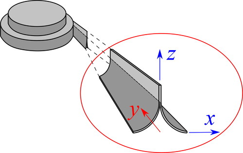
An example of a deployable boom is represented by the Storable Tubular Extendable Member (STEM) [Citation8–10]. Briefly, a single strip forms a circular cross-section, during the deployment phase. This solution has the advantages of easy fabrication and packaging, but the drawback of a significant height once packaged. A good design for deployable booms is represented by the collapsible tubular mast (CTM). This very thin composite shell structure consists of a two omega-shaped closed cross-section. The section ensures large stiffness, giving high dimensional stability and enabling the boom to be coiled in a small area. This type of boom was first adopted during the Viking 1 and 2 [Citation11] robotic explorations, which goal was to collect samples of the soil on the Mars surface. On that occasion, a thin metal sheet was used for the manufacturing of the CTMs. Afterwards, several studies on the adoption of composite materials were conducted in the 1970s regarding the adoption of carbon fiber reinforced plastic. However, the first usage of composite CTMs dates back after 15 years, and they were employed under the European Space Agency umbrella [Citation12]. In addition to these first designs of deployable booms, Murphey and Banik [Citation13] invented the Triangular Rollable And Collapsible (TRAC), developed by the Air Force Research Laboratory. Its cross-section gives to TRAC larger bending stiffness (around 10 and 34 times more than CTM and STEM booms, respectively) and packaging efficiency compared to CTM, STEM [Citation14] and bi-STEM booms [Citation15] solutions. It consists of two circular domains made of tape-spring that are attached along the common edge (web). shows an example of the TRAC boom. Moreover, the curved flanges of the TRAC require smaller strain energy than previous booms, giving the possibility of the employment of thicker materials. Metallic TRAC booms was used for the deployment of the solar sails Planetary Society’s LightSail-1 [Citation16], LightSail-2 [Citation17] and NASA’s NanoSail-D [Citation18, Citation19]. More recently, it has been found that metallic TRAC suffers from thermal gradients, inducing large deflections when the two flanges undergo large thermal gradients, for instance, in solar sails applications [Citation20]. For this reason, several studies were carried out about composite TRAC booms. Murphey and Banis [Citation13] stated that the best stacking sequence to match thermal requirements and to prevent the bifurcation of the flanges in the rolled configuration is [0° tape, 45° weave, 0° tape] for each circular boom flange, where 0° is the longitudinal direction of the deployable structure.
Figure 1. Deployment phase of a TRAC.
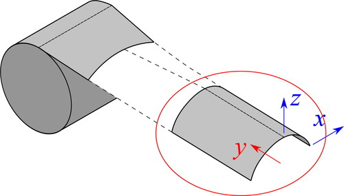
Another type of boom structure is represented by the tape-springs. They have the advantage of a low cost and easy adoption. But such steel curved thin shells offer a very simple idea with elastic behavior and the capability to be easily packaged. Tape-springs are widely adopted for a large number of applications, including high-resolution deployable telescope [Citation21] and the deployment of collapsible rib-tensioned surface [Citation22] and rigid-panels [Citation23]. In the aforementioned applications, tape-springs are used as self-locking hinges. Another way to use it is based on the coiling of the strip instead of folding with the same principle as industrial tape-measure like the deployment cassette of bi-STEM [Citation24].
Consider a TRAC boom as shown in . It is first stowed around a cylindrical hub and then deployed into the configuration with two curved flanges and one common web. During its deployment phase, three different regions can be highlighted:
Coiled region, where the boom is furled around a cylindrical hub depicted in ;
Ploy region, where the deployable structure is being uncoiled but has not reached its stable form yet. It is shown by dashed lines in ;
Uncoiled region, where the structure is completely deployed and stable.
The same domains can be highlighted in a tape-spring, as depicted in .
Figure 2. Deployment phase of a tape-spring.
In this article, both TRAC and tape spring coilable booms are analyzed and their geometrical nonlinear behavior is investigated. In particular, the performances of ultra-thin composite TRAC booms loaded in bending are analyzed, aiming to study their buckling behavior under pure bending. This kind of applications shares characteristics with other types of thin-walled beams, such as T-shaped beams, where local buckling phenomena within the web and a global lateral-torsional buckling mode appear [Citation25]. These collapsible longerons are prone to suffering instabilities and failure mechanisms as a consequence of the large displacements and rotations happening in the coiling and deployment phase. In fact, during both the coiling phase and in the deployed configuration, due to the nature of the cross-section, which is open and thin-walled, TRAC booms show complex nonlinear behavior [Citation26]. Moreover, the localized buckling, which was observed to be the first buckling mode when the booms are loaded under pure bending [Citation26, Citation27], may induce localized material failure [Citation28, Citation29]. In this context, the availability of appropriate mathematical models for the accurate prediction of the stiffness properties as well as the stress state within deployable longerons is of paramount importance for design and verification. The finite element method (FEM) can be used to develop reliable mathematical models for this kind of structure. For instance, Banik and Murphey [Citation6] accurately predicted the behavior of thick booms (around 1 mm) using nonlinear finite elements (FEs). An optimization procedure of the cross-section of ultra-thin booms (less than 100 μm), with the aim of reducing the effects of a shape imperfection during the boom collapsing, was conducted by Bessa and Pellegrino [Citation30].
Predicting stiffness and stress distribution accurately in both linear and nonlinear regimes is of great importance for design and verification. However, modern FEs show time-consuming procedures for this kind of analysis and it was demonstrated by Pagani et al. [Citation31] that the first-order shear deformation theories and von Kármán strain approximations, which is the theory often used by commercial softwares, is not effective when dealing with moderate and large rotations of thin structures. In order to develop a model able to accurately predict the stiffness and stress distribution in the geometrical nonlinear regime, the Carrera unified formulation (CUF) [Citation32, Citation33] is used in this article. CUF makes use of arbitrary expansion functions to evaluate the three-dimensional displacement field, starting from the unknowns evaluated by the FEM. In this way, the stiffness matrix and the related FE arrays, can be written in a unified form by the so-called “fundamental nuclei.” Those nuclei represent the basic building block that can be expanded according to the adopted expansion functions. Consequently, the user can a priori choose the structural theory to be adopted for the selected analysis. CUF was employed for geometrical nonlinear analyses in the pioneering works by Pagani and Carrera for the static analysis of isotropic [Citation34] and composite [Citation35] beams. Recently, this formulation was extended for the analysis of plates [Citation36] and shells [Citation37, Citation38] and for the analysis of TRAC and tape spring [Citation39, Citation40]. In this article, the CUF capabilities to evaluate the 3D stress field even in a far nonlinear regime is exploited for the analysis of isotropic tape-spring and composite TRAC booms.
This article is organized as follows: (i) Section 2 described the proposed one-dimensional model of the deployable booms using CUF. The derivation of the nonlinear governing equations is briefly explained; (ii) Section 3 reports the obtained results for the geometrical nonlinear analysis of composite TRAC booms and isotropic tape-spring. Those results are compared to the available experimental solutions. Finally, the main conclusions are drawn.
2. One-dimensional numerical model of coilable booms
A Cartesian reference system is used, so that the y direction is placed in the deployment direction, and the x, z identify the cross-sectional domain. In order to develop the numerical model of the booms, this research work makes use of the CUF. CUF allows to generate one-dimensional (1D) FEs able to capture any cross-section deformation through the implementation of expansion functions. Namely, according to CUF, the three-dimensional (3D) displacement field can be written in the following unified manner
(1)
(1)
where
is the displacement vector, whose components are expressed in the general reference system (x, y, z) of and ,
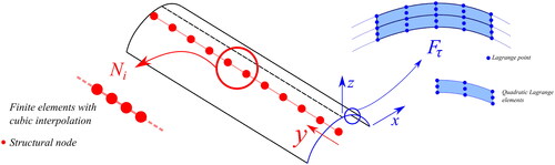
represent the cross-sectional functions depending on the x, z coordinate, τ is the sum index and M is the number of terms of the expansion in the cross-section plane assumed for the displacements. In the case Lagrange expansion is used to approximate the cross-section, every layer can be approximated as an independent entity, leading to the layer-wise approach, which has been demonstrate to produce accurate results (see [Citation41]). For the sake of brevity, Lagrange expansions are not detailed in this work, but interested readers may refer to [Citation42] for further information.
2.1. FE approximation
The FEM is adopted to discretize the structure along the y axis. Thus, the generalized displacement vector is approximated as follows:
(2)
(2)
where
stands for the ith one-dimensional shape function,
is the vector of the FE nodal parameters, i indicates summation and Nn is the number of the FE nodes per element. An exhaustive review of the shape functions Ni is given by Bathe [Citation43] and by Carrera et al. [Citation32, Citation33]. In this work, a cubic interpolation is assumed. Basically, four nodes FEs (B4) are employed to discretize the 1D structure along the y axis. and show the one-dimensional model of TRAC and tape-spring, respectively.
Figure 3. One-dimensional model of the TRAC.
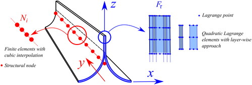
Figure 4. One-dimensional model of the tape-spring.
2.2. Constitutive and geometrical relations
The 3D stress, and strain,
components are introduced in the following, with a vectorial notation:
(3)
(3)
Thus, the geometrical relations take the following form:
(4)
(4)
where b is the matrix of the differential operators. Interested readers can find the expression of b in [Citation32, Citation33].In this work, we consider each layer to be made of linear elastic monoclinic material. Consequently, the constitutive equations at layer level hold
(5)
(5)
where and
is the material elastic matrix. For the sake of brevity, the complete expressions of the components of
matrix are not given here, but can be found in many reference texts, such as [Citation44].
2.3. Nonlinear governing equations
In this work, the principle of virtual work is recalled for the derivation of the FE governing equations, which, for a generic structure, can be expressed as:
(6)
(6)
where
is the virtual variation of the work of the internal loads (i.e. the strain energy) and
is the virtual variation of the work of the external loads.The first term of EquationEq. (6)
(6)
(6) can be written as as:
(7)
(7)
where V is the volume of the body. Introducing the geometrical (EquationEq. 4
(4)
(4) ) and contitutive relations (EquationEq. 5
(5)
(5) ) into EquationEq. (7)
(7)
(7) , it takes the following form:
(8)
(8)
The argument of the integral of the EquationEq. (8)(8)
(8) represents the so called secant stiffness matrix
The complete form of the secant stiffness matrix
is omitted here for the sake of brevity, but can be found in [Citation34, Citation45].
The right term of EquationEq. (6)(6)
(6) , omitting some mathematical steps that can be found in Carrera et al. [Citation32], can be written as:
(9)
(9)
so that EquationEq. (6)
(6)
(6) becomes:
(10)
(10)
EquationEquation (10)
(10)
(10) can be arbitrarily expanded to reach any desired theory, from low- to higher-order ones, by choosing the values for
and
to give:
(11)
(11)
where
q and p are the global, assembled FE arrays of the final structure.
EquationEquation (11)(11)
(11) represents a nonlinear algebraic system of equation for which an iterative method is needed. We employ here the same procedure detailed in the work by Pagani and Carrera [Citation35], where a Newton–Raphson scheme is used by making use of a path following constraint. The main steps of the procedure is explained in this work. This procedure demands for the linearization of the nonlinear governing equations. As a result, we need to introduce the so-called tangent stiffness matrix
The explicit form of
is not given here, but it is derived in a unified form in [Citation35]. The resultant system of equations introduces a load-scaling parameter which is taken as a variable, so an additional equation is needed for its resolution. In this work, it is represented by an opportune arc-length path-following constraint. More detail about the arc-length method adopted can be found in the works by Carrera [Citation46] and Crisfield [Citation47, Citation48].
3. Numerical results
Numerical results deal with the geometrical nonlinear static analysis of the TRAC boom and a tape-spring. For both cases, the obtained solutions are compared with experimental ones. Moreover, the case of different fiber orientations of the TRAC material is investigated.
3.1. TRAC
First analysis regards a typical TRAC boom employed in aerospace applications. describes the geometry and the stacking sequence of the structure where t represents the thickness of the curved flange and it is equal to 80 μm, r is its curvature radius equal to 12.7 mm, ϑ is the sweep angle equal to 90°, the flat vertical web h is 8 mm long and total length L of the TRAC is equal to 570 mm. The displayed stacking sequence reveals three layers for the curved flange and seven layers for the flat web, and the properties of the implemented material are reported in , where CF represents a unidirectional carbon fiber pre-preg tape with epoxy resin and GFPW stands for E-glass fabric glass fiber plain weave pre-preg with epoxy resin.
Figure 5. Geometry and stacking sequence of the composite TRAC subjected to positive and negative moments Mx. The blue color indicates the CF layers, the red color indicates the CFPW material.
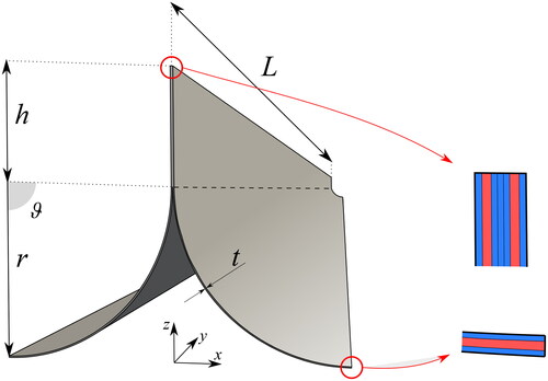
Table 1. Material properties of the composite TRAC.
shows the geometrical nonlinear results obtained with simply supported boundary conditions and applied moments around x axis on both sides. The obtained equilibrium curve is reported against the experimental results. The experiment setup for the bending test experiments is detailed in [Citation40]. Briefly, the rotations at the ends of the TRAC are independently controlled by the testing machine. The TRAC can shorthen, since only one end is constrained in the longitudinal direction. End rotations are measured by calibrated camera. The accuracy of the proposed methodology is evident. Important equilibrium states of the equilibrium curve are represented by “A” and “C” for negative and positive moments, respectively. These equilibrium states correspond to the buckling (localized or global) phenomena occurring to the structure.
Figure 6. Nonlinear static solution for the composite TRAC subjected to positive and negative moments Mx.
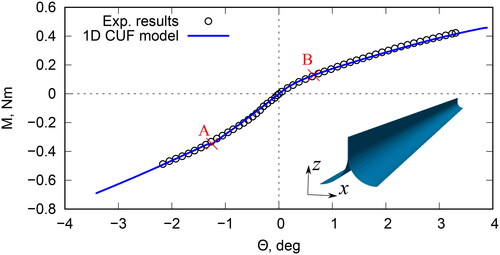
For a better understanding of the situation, relevant deformed configurations are reported. As far as the negative moment Mx is concerned, shows the deformed configurations of the point “A” of , where the localized buckling phenomena occurs. In particular, reports the numerical solution, whereas the shows the localized buckling detected by the experimental test. Clearly, the numerical simulation is perfectly in agreement with the available experiment test.
Figure 7. Nonlinear equilibrium states correspondent to the point “A” of for the composite TRAC subjected to a negative moment Mx. Numerical (a) vs. experimental (b) solutions (elaborated from Ref. [Citation49]).
![Figure 7. Nonlinear equilibrium states correspondent to the point “A” of Figure 6 for the composite TRAC subjected to a negative moment Mx. Numerical (a) vs. experimental (b) solutions (elaborated from Ref. [Citation49]).](/cms/asset/1265c090-03ad-4cca-bfcd-0f2f00a60543/umcm_a_2037173_f0007_c.jpg)
About positive moment Mx, the global buckling phenomena is highlighted in . As for the previous case, the numerical simulation is able to describe the post-buckling of the composite boom, reproducing the global web waviness from the experimental results, shown in .
Figure 8. Nonlinear equilibrium states correspondent to the point “B” of for the composite TRAC subjected to a positive moment Mx. Numerical (a) vs. experimental (b) solutions (elaborated from Ref. [Citation49]).
![Figure 8. Nonlinear equilibrium states correspondent to the point “B” of Figure 6 for the composite TRAC subjected to a positive moment Mx. Numerical (a) vs. experimental (b) solutions (elaborated from Ref. [Citation49]).](/cms/asset/a4d2dc0e-8a5a-46fb-8add-ae472369ba37/umcm_a_2037173_f0008_c.jpg)
In addition, two additional stacking sequence are considered, changing the orientation of the CF layers, so that and
are analyzed. The results from the geometrical nonlinear simulation are reported in and the evaluated buckling-like phenomena are highlighted with circles of the same color as the considered stacking sequence.
Figure 9. Nonlinear static solution for the composite TRAC subjected to positive and negative moments Mx considering the and
stacking sequences.
![Figure 9. Nonlinear static solution for the composite TRAC subjected to positive and negative moments Mx considering the [±45GFWP/45CF/±45GFWP] and [±45GFWP/90CF/±45GFWP] stacking sequences.](/cms/asset/e7cacc30-af04-43a8-9808-d2af99eeb476/umcm_a_2037173_f0009_c.jpg)
The post-buckling deformed configurations are reported in and . Clearly, localized buckling are detected when negative moments are applied, whereas a global web waviness is detected with positive moments.
Figure 10. Nonlinear equilibrium states correspondent to the buckling of the TRAC subjected to negative (a) and positive (b) moments Mx. The equilibrium states correspond to the red circled of the .
![Figure 10. Nonlinear equilibrium states correspondent to the buckling of the [±45GFWP/45CF/±45GFWP] TRAC subjected to negative (a) and positive (b) moments Mx. The equilibrium states correspond to the red circled of the Figure 9.](/cms/asset/17bf41c8-4eb6-431a-86b5-1f9e0b26900f/umcm_a_2037173_f0010_c.jpg)
Figure 11. Nonlinear equilibrium states correspondent to the buckling of the TRAC subjected to negative (a) and positive (b) moments Mx. The equilibrium states correspond to the gray circled of the .
![Figure 11. Nonlinear equilibrium states correspondent to the buckling of the [±45GFWP/90CF/±45GFWP] TRAC subjected to negative (a) and positive (b) moments Mx. The equilibrium states correspond to the gray circled of the Figure 9.](/cms/asset/be3313d0-8f20-4f3d-94f3-c42487f0ee52/umcm_a_2037173_f0011_c.jpg)
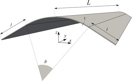
3.2. Metallic tape spring
The second analysis case deals with a metallic tape-spring. The geometric characteristics are depicted in . The structure has a curvature radius R equal to 12.3 mm, curvature angle ϑ equal to 62°, length of the flat domains l equals 6.1 mm, total length L is 170 mm and the thickness t is 0.114 mm. The considered tape is made with isotropic steel with Young modulus E 210,000 MPa and Poisson’s modulus ν equal to 0.3.
Figure 12. Geometry of the isotropic tape.
The obtained numerical results are compared with those from experimental tests. shows the 170 mm sample that is the subject of this study. The sample was opportunely obtained from a commercial tape-spring. Testing was done using the Fischer’s machine [Citation50], which makes use of two rotation control dials to apply moment at the free ends of the samples. Note that one side of the machine is fixed, while the other end is allowed to translate.
Figure 13. A 170 mm sample of commercial tape-spring. Figure elaborated from Ref. [Citation39].
![Figure 13. A 170 mm sample of commercial tape-spring. Figure elaborated from Ref. [Citation39].](/cms/asset/ffca6e68-ed34-4091-852b-1890448fa75e/umcm_a_2037173_f0013_c.jpg)
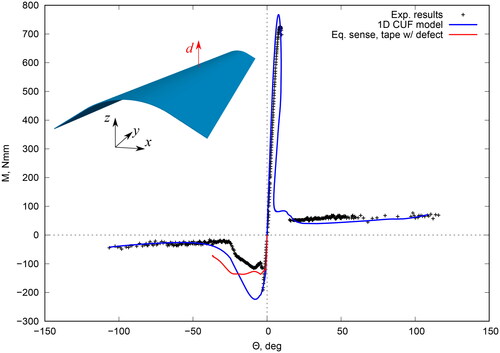
This structure is loaded with positive and negative moments at its ends, whereas simply supported boundary conditions are employed to numerically reproduce the experimental setup. The numerical geometrical nonlinear solution is reported in . Clearly an overall match between the numerical solution and the experimental results is demonstrated, especially for positive moments.
Figure 14. Nonlinear static solution for the isotropic tape subjected to positive and negative moments Mx.
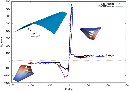
Some relevant deformed numerical and experimental configurations are reported hereafter. shows the deformed configurations correspondent to the red crosses of . Clearly, the numerical deformations are in a perfect agreement with the experiments.
Figure 15. Nonlinear equilibrium states correspondent to crosses of for the isotropic tape subjected to a positive moment Mx. Numerical (a) vs. experimental (b) solutions, elaborated from Ref. [Citation39].
![Figure 15. Nonlinear equilibrium states correspondent to crosses of Figure 14 for the isotropic tape subjected to a positive moment Mx. Numerical (a) vs. experimental (b) solutions, elaborated from Ref. [Citation39].](/cms/asset/9eec3174-203f-44a0-96eb-a38e6acf2d9e/umcm_a_2037173_f0015_c.jpg)
Finally, the deformed configurations correspondent to the circles of the are reported in . Clearly, there is a mismatch between numerical simulation and experimental results, both in terms of nonlinear static curve and deformed configurations. In fact, by looking at , it is clear that the structure is not perfectly symmetric, and an imperfection is present within the structure.
Figure 16. Nonlinear equilibrium states correspondent to circles of for the isotropic tape subjected to a positive moment Mx. Numerical (a) vs. experimental (b) solutions, elaborated from Ref. [Citation39].
![Figure 16. Nonlinear equilibrium states correspondent to circles of Figure 14 for the isotropic tape subjected to a positive moment Mx. Numerical (a) vs. experimental (b) solutions, elaborated from Ref. [Citation39].](/cms/asset/782292a4-eff2-4330-a9ef-380e503629aa/umcm_a_2037173_f0016_c.jpg)
To account for this aspect, another numerical simulation is performed, including a defect load as depicted in .
Figure 17. Nonlinear static solution for the isotropic tape using a defect load.
The numerical results are closer to the experimental ones, as also highlighted by the deformed configurations in .
Figure 18. Nonlinear equilibrium states correspondent to crosses of for the isotropic tape subjected to a positive moment Mx, using a defect load for the numerical simulations. Experimental figures elaborated from Ref. [Citation39].
![Figure 18. Nonlinear equilibrium states correspondent to crosses of Figure 14 for the isotropic tape subjected to a positive moment Mx, using a defect load for the numerical simulations. Experimental figures elaborated from Ref. [Citation39].](/cms/asset/afd47425-4046-4ac2-a121-6de5fc7c33b6/umcm_a_2037173_f0018_c.jpg)
4. Conclusions
This work has explored the use of the CUF for the simulations of the geometrical nonlinear analysis of composite TRAC and isotropic tape-spring booms. The use of CUF is justified due to its hierarchical nature. In fact, it allows to expresses the governing equations in terms of fundamental nuclei, which are invariant of the theory approximation order and both the efficiency and the accuracy of the analysis can be opportunely tuned. The efficacy of the proposed method in describing near and far post-buckling mechanics of the booms is demonstrated via dedicated experiments. The model is able to foresee limit loads and steady-state moments. Conversely, it has been shown that the structure is very sensitive to geometry defects in the case of equal sense moment for both considered booms. From this standpoint, a dedicated sensitivity analysis by CUF will be performed. Moreover, a different stacking sequence for the composite materials of the TRAC longerons is considered and the results offer interesting points for possible future designs, in terms of critical applied moments which induce localized and global buckling phenomena.
Acknowledgments
The authors acknowledge the Space Structures Laboratory at California Institute of Technology, USA, for providing the experimental data and Prof. Sergio Pellegrino and Dr. Armanj Hasanyan for the fruitful discussions.
Disclosure statement
No potential competing interest was reported by the authors.
Additional information
Funding
References
- M. Leipold, H. Runge, and C. Sickinger, Large SAR membrane antennas with lightweight deployable booms, 28th ESA Antenna Workshop on Space Antenna Systems and Technologies, ESA/ESTEC, Noordwijk, Netherlands, pp. 1–8, 2005.
- L. Blanchard, A tape-spring hexapod for deployable telescopes: Dynamics, ESA Special Publication, The Netherlands, pp. 1–5, 2006.
- D. Campbell, R. Barrett, M. S. Lake, L. Adams, E. Abramson, M. R. Scherbarthn, J. S. Welsh, G. Freebury, N. Beidleman and J. Abbot, Development of a novel, passively deployed roll-out solar array, 2006 IEEE Aerospace Conference, Big Sky, MT, USA, pp. 1–9, 2006.
- B. Hoang, S. White, B. Spence, and S. Kiefer, Commercialization of deployable space systems’ roll-out solar array (ROSA) technology for space systems loral (SSL) solar arrays, 2016 IEEE Aerospace Conference, Big Sky, MT, USA, pp. 1–12, 2016. DOI: 10.1109/AERO.2016.7500723.
- M. Leipold, M. Eiden, C.E. Garner, L. Herbeck, D. Kassing, T. Niederstadt, T. Krüger, G. Pagel, M. Rezazad, H. Rozemeijer and W. Seboldt, Solar sail technology development and demonstration, Acta Astronaut. (UK)., vol. 52, no. 2–6, pp. 317–326, 2003. DOI: 10.1016/S0094-5765(02)00171-6.
- J. Banik and T.W. Murphey, Performance validation of the triangular rollable and collapsible mast, 24th Annual AIAA/USU Conference on Small Satellites, Logan, UT, US, pp. 1–8, 2010.
- F. Royer and S. Pellegrino, Ultralight ladder-type coilable space structures, 2018 AIAA Spacecraft Structures Conference, Kissimmee, Florida, USA, pp. 1–14, 2018. DOI: 10.2514/6.2018-1200.
- F.P.J. Rimrott, Storable tubular extendible member: a unique machine element, Mach Des., vol. 37, no. 28, pp. 156–165, 1965.
- C. Hazelton, K. Gall, E. Abrahamson, M. Lake, and R. Denis, Development of a prototype elastic memory composite stem for large space structures, 44th AIAA/ASME/ASCE/AHS/ASC Structures, Structural Dynamics, and Materials Conference, Norfolk, Virginia, USA, 2003. DOI: 10.2514/6.2003-1977.
- K. Higuchi, K. Watanabe, A. Watanabe, H. Tsunoda, and H. Yamakawa, Design and evaluation of an ultra-light extendible mast as an inflatable structure, 47th AIAA/ASME/ASCE/AHS/ASC Structures, Structural Dynamics, and Materials Conference 14th AIAA/ASME/AHS Adaptive Structures Conference 7th, Newport, Rhode Island, US, 2006. DOI: 10.2514/6.2006-1809.
- D.S. Crouch, Mars viking surface sampler subsystem, 25th Conference on Remote Systems Technology, pp. 142–151, 1977.
- M.A. Aguirre-Martinez, R. Bureo-Dacal, F. Del Campo, and M. Fuentes, The ctm family of masts and the ctm engineering model, 3rd European Space Mechanisms & Tribology Symposium, Madrid, Spain, 1987.
- T.W. Murphey and J. Banik, Triangular rollable and collapsible boom, US Patent 7,895,795, 2011.
- F. Roybal, J. Banik, and T.W. Murphey, Development of an elastically deployable boom for tensioned planar structures, 48th AIAA/ASME/ASCE/AHS/ASC Structures, Structural Dynamics, and Materials Conference, Honolulu, Hawaii, USA, pp. 1–14, 2007. DOI: 10.2514/6.2007-1838.
- M.W. Thomson, Deployable and retractable telescoping tubular structure development, The 28th Aerospace Mechanisms Symposium, Cleveland, Ohio, USA, 1994.
- C. Biddy and T. Svitek, Lightsail-1 solar sail design and qualification, 41st Aerospace Mechanisms Symposium, Pasadena, California, USA, pp. 451–463, 2012.
- B. Betts, D. A. Spencer, B. Nye, R. Munakata, J. M. Bellardo, S. D. Wong, A. Diaz, R. W. Ridenoure, B. A. Plante, J. D. Foley and J. Vaughn, 2: Controlled solar sailing using a cubesat, 4th International Symposium on Solar Sailing, Kyoto, Japan, pp. 1–7, 2017.
- M. Whorton, A. Heaton, R. Pinson, G. Laue, and C. Adams, Nanosail-d: the first flight demonstration of solar sails for nanosatellites, 22nd Annual AIAA/USU Conference on Small Satellites, Logan, Utah, USA, pp. 1–6, 2008.
- L. Johnson, M. Whorton, A. Heaton, R. Pinson, G. Laue, and C. Adams, Nanosail-d: A solar sail demonstration mission, Acta Astronaut. (UK)., vol. 68, no. 5–6, pp. 571–575, 2011. DOI: 10.1016/j.actaastro.2010.02.008.
- O.R. Stohlman and E. Loper, Thermal deformation of very slender TRAC booms, 3rd AIAA Spacecraft Structures Conference, San Diego, California, USA, pp. 1–15, 2016. DOI: 10.2514/6.2016-1469.
- G. Pica, L. Ciofaniello, S. Mattei, M.R. Santovito, and R. Gardi, High-resolution deployable telescope for satellite applications, Sensors, Systems, and Next-Generation Satellites VII, vol. 5234, pp. 531–538, 2004.
- C.Y. Lai and S. Pellegrino, Design and Testing of a 1.5 m Offset CRTS Demonstrator, Department of Engineering, University of Cambridge, United Kingdom, 2001.
- K.A. Seffen and S. Pellegrino, Deployment of a Rigid Panel by Tape-Springs, Department of Engineering, University of Cambridge, United Kingdom, 1997.
- D.A. Galletly and S.D. Guest, Bistable composite slit tubes. I. A beam model, Int. J. Solids Struct., vol. 41, no. 16–17, pp. 4517–4533, 2004. DOI: 10.1016/j.ijsolstr.2004.02.036.
- E. Corona and M.S. Ellison, Plastic buckling of t-beams under pure bending, J. Eng. Mech., vol. 123, no. 5, pp. 466–474, 1997. DOI: 10.1061/(ASCE)0733-9399(1997)123:5(466).
- T.W. Murphey, D. Turse, and L. Adams, TRAC boom structural mechanics, 4th AIAA Spacecraft Structures Conference, Grapevine, Texas, USA, pp. 1–13, 2017. DOI: 10.2514/6.2017-0171.
- C. Leclerc, L.L. Wilson, M.A. Bessa, and S. Pellegrino, Characterization of ultra-thin composite triangular rollable and collapsible booms, 4th AIAA Spacecraft Structures Conference, Grapevine, Texas, USA, pp. 1–15, 2017. DOI: 10.2514/6.2017-0172.
- C. Leclerc, A. Pedivellano, and S. Pellegrino, Stress concentration and material failure during coiling of ultra-thin TRAC booms, 2018 AIAA Spacecraft Structures Conference, Kissimmee, Florida, USA, pp. 1–16, 2018. DOI: 10.2514/6.2018-0690.
- K. Cox and K.A. Medina, Scalability of triangular rollable and collapsible booms, AIAA Scitech 2019 Forum San Diego, California, USA, pp. 1–20, 2019. DOI: 10.2514/6.2019-2026.
- M.A. Bessa and Se Pellegrino, Design of ultra-thin composite deployable shell structures through machine learning. IASS Annual Symposia, pp. 1–8, Hamburg, Germany, 2017.
- A. Pagani, E. Carrera, and R. Augello, Evaluation of various geometrical nonlinearities in the response of beams and shells, AIAA J., vol. 57, no. 8, pp. 3524–3533, 2019. DOI: 10.2514/1.J057877.
- E. Carrera, G. Giunta, and M. Petrolo, Beam Structures: Classical and Advanced Theories, John Wiley & Sons, United States, 2011.
- E. Carrera, M. Cinefra, M. Petrolo, and E. Zappino, Finite Element Analysis of Structures through Unified Formulation, Wiley, Chichester, West Sussex, UK, 2014.
- A. Pagani and E. Carrera, Unified formulation of geometrically nonlinear refined beam theories, Mech. Adv. Mater. Struct., vol. 25, no. 1, pp. 15–31, 2018. DOI: 10.1080/15376494.2016.1232458.
- A. Pagani and E. Carrera, Large-deflection and post-buckling analyses of laminated composite beams by carrera unified formulation, Compos. Struct., vol. 170, pp. 40–52, 2017. DOI: 10.1016/j.compstruct.2017.03.008.
- A. Pagani, E. Daneshkhah, X. Xu, and E. Carrera, Evaluation of geometrically nonlinear terms in the large-deflection and post-buckling analysis of isotropic rectangular plates, Int. J. Non. Linear Mech., vol. 121, pp. 103461, 2020. DOI: 10.1016/j.ijnonlinmec.2020.103461.
- B. Wu, A. Pagani, W.Q. Chen, and E. Carrera, Geometrically nonlinear refined shell theories by carrera unified formulation, Mech. Adv. Mater. Struct., vol. 28, no. 16, pp. 1721–1721, 2021. DOI: 10.1080/15376494.2019.1702237.
- E. Carrera, A. Pagani, R. Augello, and B. Wu, Popular benchmarks of nonlinear shell analysis solved by 1D and 2D cuf-based finite elements, Mech. Adv. Mater. Struct., vol. 27, no. 13, pp. 1098–1109, 2020. DOI: 10.1080/15376494.2020.1728450.
- A. Pagani, E. Carrera, A. G. de Miguel, A. Hasanyan, S. Pellegrino, H. R. Narravula, E. Zappino, Efficient analysis of geometrically nonlinear deployable thin shell structures using Carrera unified formulation, 70th International Astronautical Congress (IAC), Washington D.C., USA, 2019.
- A. Pagani, E. Carrera, A. Hasanyan, and S. Pellegrino, Advanced simulation and testing of composite TRAC longerons, 71st International Astronautical Congress (IAC), IAC CyberSpace Edition, 2020.
- E. Carrera, Evaluation of layerwise mixed theories for laminated plates analysis, AIAA J., vol. 36, no. 5, pp. 830–839, 1998. DOI: 10.2514/2.444.
- A. Pagani, E. Carrera, R. Augello, and D. Scano, Use of lagrange polynomials to build refined theories for laminated beams, plates and shells, Compos. Struct., vol. 276, pp. 114505, 2021. DOI: 10.1016/j.compstruct.2021.114505.
- K.J. Bathe, Finite Element Procedure, Prentice Hall, Upper Saddle River, New Jersey, 1996.
- O.O. Ochoa and J.N. Reddy, Finite Element Analysis of Composite Laminates, Springer, Germany, pp. 37–109, 1992.
- E. Carrera, A. Pagani, and R. Augello, Evaluation of geometrically nonlinear effects due to large cross-sectional deformations of compact and shell-like structures, Mech. Adv. Mater. Struct., vol. 27, no. 14, pp. 1269–1269, 2020. DOI: 10.1080/15376494.2018.1507063.
- E. Carrera, A study on arc-length-type methods and their operation failures illustrated by a simple model, Comput Struct., vol. 50, no. 2, pp. 217–229, 1994. DOI: 10.1016/0045-7949(94)90297-6.
- M.A. Crisfield, A fast incremental/iterative solution procedure that handles snap-through. Computational Methods in Nonlinear Structural and Solid Mechanics, Elsevier, Amsterdam, Netherlands, 1981.
- M.A. Crisfield, An arc-length method including line searches and accelerations, Int. J. Numer. Meth. Engng., vol. 19, no. 9, pp. 1269–1289, 1983. DOI: 10.1002/nme.1620190902.
- C. Leclerc and S. Pellegrino, Nonlinear elastic buckling of ultra-thin coilable booms, Int. J. Solids Struct., vol. 203, pp. 46–56, 2020. DOI: 10.1016/j.ijsolstr.2020.06.042.
- A. Fischer, Bending Instabilities of Thin-Walled Transversely Curved Metallic Strips, University of Cambridge, Department of Engineering, England, 1995.