
 ?Mathematical formulae have been encoded as MathML and are displayed in this HTML version using MathJax in order to improve their display. Uncheck the box to turn MathJax off. This feature requires Javascript. Click on a formula to zoom.
Abstract
Metalite is a new class of antisymmetric composite laminates composed of angle-plies, 0-degree, and 90-degree plies, presenting unique properties. These include extremely thin laminates suitable for minimum gauge applications, remarkable weight savings compared to conventional quads, adjustable zero and negative coefficients of thermal expansion (CTE), ease of manufacturing, excellent ability to adjust mode frequency, change sound radiation characteristics, and high tunability. In this study, Metalite laminates ranging from 3 to 8 plies are described using their feasible spaces and compared with quads, detailing the weight savings achieved for hard, soft, and neutral laminates. Through an experimental study, the CTE value of a hybrid Metalite is correlated with theory, demonstrating how to tune zero and negative CTE values. The proposed work offers significant benefits through practical solutions for designing and manufacturing lightweight composite laminates with unique properties.
Introduction
Common composite laminates are typically constructed using 0, 90 and ±45-degree plies, commonly referred to as quads [Citation1–3]. These layups have been in use for over sixty years [Citation4]. By altering ply orientations and stacking sequences, numerous permutations of quad laminates can be achieved, allowing them to meet the majority of aerospace industry requirements. To guarantee manufacturability and improve damage tolerance, various layup design guidelines are generally employed, including midplane symmetry, the 10% rule, and blending techniques [Citation5–7]. This leads to a complicated optimization design procedure. Designing quad laminates, particularly when accounting for ply drop-offs, becomes highly complex and time-intensive to fulfill application needs and reduce laminate weight [Citation8–13]. Furthermore, quads display flexural anisotropy, which can cause distortion during the manufacturing process [Citation14,Citation15]. They also involve long and complex stacking sequences that are challenging to manufacture and have a constrained feasible space, limiting their applicability across the full range of composite applications [Citation16].
Therefore, there is interest in exploring alternatives by proposing general formulations where ply orientations are unrestricted. When plies are stacked with random orientations of axes of orthotropy relative to a fixed reference system, the resulting laminate is typically completely anisotropic, exhibiting unique coupling behaviors, such as coupling between in-plane (extension or membrane) and out-of-plane (bending or flexure) actions, as well as coupling between in-plane shear and extension, and out-of-plane bending and twisting. However, many applications require decoupling of in-plane and out-of-plane behaviors. Traditionally, this decoupling is achieved through symmetric stacking sequences [Citation17]. While achieving in-plane orthotropy (e.g. any balanced symmetric laminate) [Citation17,Citation18] is relatively straightforward, achieving bending orthotropy is more challenging. Some authors even assume that coefficients D16 and D26 are negligible [Citation19]. However, this assumption is incorrect. All symmetrical laminates with plies oriented in directions other than 0 and 90 degrees have D16 ≠ 0 and D26 ≠ 0, indicating anisotropy in bending [Citation7].
The original work by Bartholomew [Citation20,Citation21], which forms the basis of the Engineering Sciences Data Unit (ESDU) publication [Citation22] for the so-called definitive list of fully orthotropic angle-ply laminates, predates the findings of Caprino and Crivelli-Visconti [Citation18, Citation23], who used special antisymmetric laminates to achieve bending orthotropy. Fully orthotropic laminates can minimize distortion during manufacturing and maximize compression buckling strength [Citation24] compared to balanced and symmetric laminates, which generally exhibit flexural anisotropy. A study of a C-section tapered beam demonstrated that an antisymmetric laminate showed an improvement of over 6% in consolidation compared to the baseline (symmetric) laminate and was significantly less warped [Citation25,Citation26].
Valot [Citation27] has shown that, excluding the special though important case of cross-ply laminates, the only general type of stacking sequence that produces uncoupled orthotropic laminates—with orthotropy in the same axes for bending and extension—is the antisymmetric one. Vannucci and Verchery [Citation28] and Grediac [Citation29,Citation30] have already demonstrated the existence of many uncoupled non-symmetric laminates. In fact, uncoupling appears to be an easier condition to satisfy than bending orthotropy, especially when unsymmetric sequences are considered [Citation31].
Examples of symmetric angle-ply laminates with non-symmetric cross-ply subsequences have been previously presented [Citation32] in the context of composite plate instability. These represent some of the many non-symmetric forms included in the definitive list of fully orthotropic laminates with standard angle-ply configurations, such as ±45, 0, and 90 degrees. Many of these laminates appear extraordinary in appearance and infeasible in terms of the uncoupled behavior they exhibit. The vast majority of fully orthotropic laminates is non-symmetric and lack any sub-sequence patterns, such as symmetries or repeating groups, which contradicts the assumptions on which many previous studies have been based [Citation33]. The damage tolerance of fully orthotropic laminates has been analyzed in [Citation34–36]. A review of non-symmetric laminates is presented in [Citation37]. However, none of the types of laminates mentioned have captured the interest of composite engineers and decision-makers, leading to the continued majority use of symmetric laminates, especially quads, in the composites industry.
This paper introduces Metalite, a new class of antisymmetric composite laminates. Specifically, 3- to 8-ply Metalite laminates formed by all possible ply orientations will be studied. A key property of Metalite laminates is their thinness, which allows them to replace the complex and lengthy layups of quads with a repetitive sequence of thin Metalite laminates. This substitution offers significant advantages, including weight savings through ply-drops, minimum gauge design, and ease of manufacturing. Examples of replacements for hard, soft, and neutral laminates will be detailed. Another characteristic of Metalite laminates that will be emphasized is their extensive feasible domain, surpassing any other type of composite laminate. Other properties will also be pointed out, such as active structural acoustic control using piezoelectric fiber-reinforced composite materials, improved sound quality of composite laminates, avoidance of structural resonance, and reduced vibration and sound radiation of composite plates. Additionally, hybrid Metalite laminates will be described, with desirable properties such as zero and large negative CTE for bondless-fastenerless joints.
Section “Requirements that metalite laminates meet” introduces the requirements that Metalite laminates must meet, while Section “Determining the feasible regions of Metalite laminates” studies Metalite laminates with 3 to 8 plies. Section “Hybridization of Metalite laminates” details Metalite hybrids, outlining a test plan conducted to determine the negative CTE. Brief conclusions are presented in Section “Conclusions”.
Requirements that metalite laminates meet
Metalite laminates are antisymmetric, meaning that A16 = A26 = D16 = D26 = B11 = B12 = B22 = B66 = 0. The only non-zero coupling components are B16 and B26 (, in red).
Figure 1. Scheme of [ABD] matrix of antisymmetric laminates with B16 and B26 in red.
![Figure 1. Scheme of [ABD] matrix of antisymmetric laminates with B16 and B26 in red.](/cms/asset/9e95e9f4-bd24-43ce-bee0-0b255ae3019a/umcm_a_2378369_f0001_c.jpg)
Let’s define [A*, B*, D*] as the thickness normalized stiffness matrices defined in EquationEquation 1(1)
(1) [Citation7].
(1)
(1)
In [Citation38], a criterion was proposed to define sufficiently small in-plane and out-of-plane coupling for composite laminates. According to this criterion, the largest of the absolute values of the matrix [B*] components must be less than a fraction I of the value of Trace, which can be defined in the following EquationEquations 2-4:
(2)
(2)
For antisymmetric laminates:
(3)
(3)
Trace being [Citation39–41]:
(4)
(4)
The value of I was proposed in [Citation38] to be 0.02. Experimental data [Citation7,Citation16,Citation42] validated this value. Let’s define I* as:
(5)
(5)
The two conditions that Metalite laminates must meet are:
1. Antisymmetry
2. I* < 0.02
A property of Metalite is that the laminates obtained by repeating Metalites remain uncoupled in in-plane shear and extension, as well as between out-of-plane bending and twisting. Regarding in-plane and out-of-plane coupling, the value of I* decreases hyperbolically as the number of repeats increases, according to EquationEquation 6(6)
(6) :
(6)
(6)
with r being the number of repeats.
shows the I*(average)/I*(r=1) ratio for a tapered Metalite laminate with several equidistant ply-drops using repeats of Metalite laminates.
Table 1. I*(Average)/I*(r=1) ratio for a tapered metalite laminate with several equidistant ply-drops.
On the one hand, the minimal coupling of the Metalite ABD matrices resemble the uncoupling of metal matrices. On the other hand, these laminates are exceptionally thin, allowing for significant weight savings compared to traditional quads, hence the name Metalite.
Determining the feasible regions of Metalite laminates
Due to the extensive variety of sequences categorized as Metalite, it is advantageous to define their feasible domains in terms of lamination parameters, which can be effectively illustrated graphically, as originally proposed by Fukunaga and Vanderplaats [Citation19].
Lamination parameters were initially introduced by Tsai and Pagano in 1968 [Citation43], facilitating the representation of the stiffness matrix as a linear function and significantly reducing the number of design variables. For both flat and curved composite laminates, lamination parameters serve as efficient design variables, replacing the numerous ply angles traditionally required to meet mechanical requirements in engineering applications such as buckling, post-buckling, and vibration [Citation44]. By utilizing lamination parameters, the design complexity is streamlined, reducing the maximum number of design variables to twelve. Consequently, the stiffness matrix can be linearly expressed in terms of these lamination parameters, offering a more manageable approach compared to conventional methods reliant on numerous ply orientations [Citation45]. Based on classical laminate theory, the stress-strain relationship for a composite laminate can be expressed as
(7)
(7)
where
and
are vectors of in-plane forces and moments per unit width, A, B and D are in-plane, coupling and out-of-plane stiffness matrices, ε0 is a vector of in-plane strains and κ is a vector of mid-plane curvatures.
The stiffness matrices A, B and D can be expressed in terms of twelve lamination parameters ξjk (j = 1,2,3,4; k = A, B, D) and material stiffness invariants U as shown below:
(8)
(8)
(9)
(9)
(10)
(10)
where the material stiffness invariants U and the stiffness properties Q are:
(11)
(11)
Where E11 is the longitudinal Young’s modulus, E22 is the transverse modulus, G12 is the shear modulus, νx, νy are the major, minor Poisson’s ratio, respectively, and h is the thickness of the laminate. The lamination parameters are obtained by the following integrals
(12)
(12)
where represents the ply angle at depth z below the mid-surface. For a general angle laminate, such an equation cannot be simplified further as the angle of each ply differs at different depths.
The feasible regions of lamination parameters serve as constraints when utilizing them as non-dimensional design variables [Citation23,Citation46–58]. The earliest investigations into feasible regions of lamination parameters were conducted by Miki [Citation59] and [Citation60], who defined the feasible region for in-plane or out-of-plane stiffness of orthotropic laminates. Subsequently, Fukunaga and Sekine [Citation61,Citation62] determined the feasible regions for the four in-plane or four out-of-plane lamination parameters of symmetric laminates. Diaconu et al. [Citation63] extended this work by presenting feasible regions in the general design space encompassing all twelve lamination parameters, demonstrating that these regions are finite convex spaces. Setoodeh et al. [Citation64] developed a method to approximate the boundaries of the general feasible region for lamination parameters using the convex hull method. Bloomfield et al. [Citation65,Citation66] contributed by devising closed-form solutions to define feasible regions for any predefined finite orientation set.
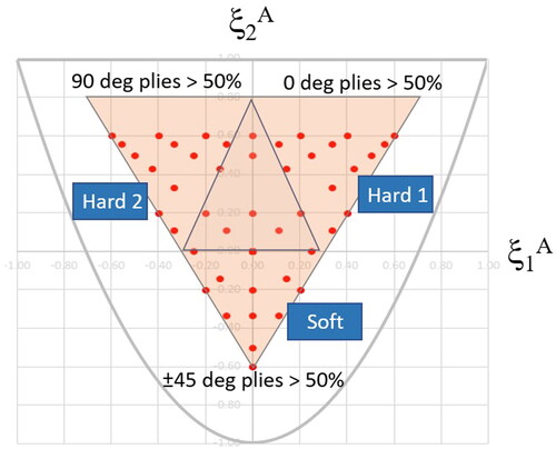
Throughout this study, the feasible domains of Metalite laminates will be compared to those of quads. shows the feasible domain for quads meeting the 10% rule (pink). Quads ranging from 8 to 20 plies are represented by red dots. Four distinct triangles can be identified within the quad space: quads with more than 50% of plies oriented at 0 degrees are enclosed in the triangle on the right (Hard 1), those with more than 50% at 90 degrees in the triangle on the left (Hard 2), and those with more than 50% at ±45 degrees at the bottom (Soft). The remaining laminates, termed neutral laminates, are situated within the central triangle.
Figure 2. Feasible domain for quads meeting the 10% rule (pink). 8- to 20-ply quads are represented by red dots.
3-ply laminates
The 3-ply antisymmetric laminates [ϕ/0/-ϕ] and [ϕ/90/-ϕ] are highly efficient in terms of weight savings due to their smaller building blocks, allowing for greater number of repeats and potential weight savings using ply-drops.
The feasible domains that meet the Metalite requirements are located in areas very close to the following cross-ply laminates: [0]3 at ξ1A=1, ξ2A=1, [0/90/0] at ξ1A=0.333, ξ2A=1, [90/0/90] at ξ1A= −0.333, ξ2A=1 and [90]3 at ξ1A= −1, ξ2A=1. The range of angles varies such that 0 ≤ ϕ ≤ 3 deg and 87 ≤ ϕ ≤ 90 deg. These 3-ply laminates are particularly suitable for minimum gauge applications when thin plies [Citation67–74] are used, such as 0.035 mm thin-plies, resulting in a laminate thickness of 0.105 mm.
4-ply laminates
The feasible domain of 4-ply laminates is illustrated in . The cross-ply laminates in this case are [0]4 at ξ1A=1, ξ2A=1, [0/90/90/0] at ξ1A=0, ξ2A=1 and [90]4 at ξ1A= −1, ξ2A=1.
Figure 3. Feasible domain of 4-ply Metalite laminates (green) and quads (pink).
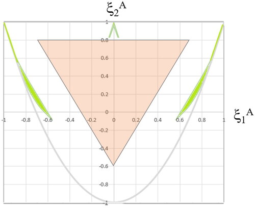
In addition to areas close to cross-ply laminates, two curved strips are apparent. The laminates within these strips are of interest when significantly hard laminates are required and equally subjected to in-plane shear stress. Some examples of Metalite laminates [+ϕ1/-ϕ2/+ϕ2/-ϕ1] located in these strips are shown in .
Table 2. Examples of Metalite laminates [+ϕ1/-ϕ2/+ϕ2/-ϕ1] and their in-plane lamination parameters.
displays the I* values for one repetition and ten typical prepregs. All values are consistently below 0.02.
Table 3. I* values for one repetition and ten typical prepregs.
Using 0.035 mm thin plies, the thickness of the laminate in this case is 0.144 mm. Thin antisymmetric cross-ply laminates are of particular interest in piezoelectric applications for sensors and actuators in active vibration control [Citation75]. The Metalite [0/90/90/0] laminate, due to its antisymmetric structure and thinness, is especially suitable for applications involving active structural acoustic control of laminated composite plates using piezoelectric fiber-reinforced composite materials for the constraining layer of active constrained layer damping treatment [Citation75–80].
5-ply laminates
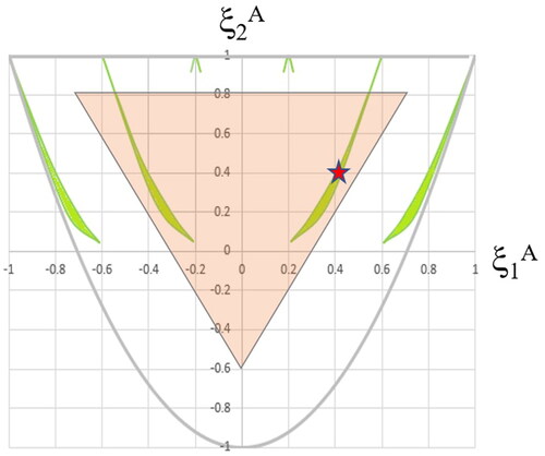
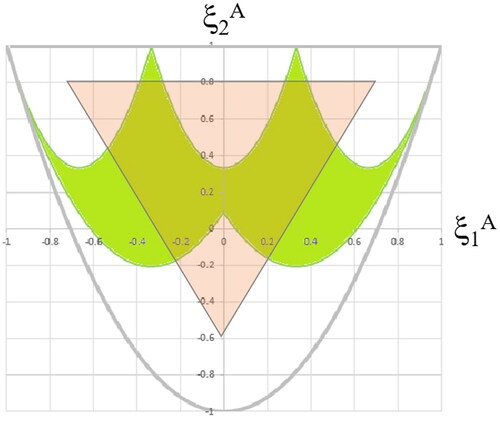
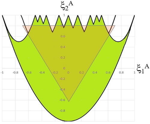
For 5-ply laminates, the cross-ply laminates are located at ξ2A=1 and ξ1A=1, 0.6, 0.2, −0.2, −0.6, −1. The cross-ply associated are [0]5, [0/0/90/0/0], [0/90/0/90/0], [90/0/90/0/90], [90/90/0/90/90] and [90]5, respectively. In addition to the areas close to these cross-ply laminates, four curved stripes appear, two lateral and two others within the Hard 1 and Hard 2 zones of the quad domain. depicts the Metalite feasible domain for 5 plies (green) alongside quads (pink). The red star highlights the location of the following example.
Figure 4. Metalite feasible domain of 5 plies (green) and quads (pink).
Using a 0.035 mm thin ply, the thickness of the laminate in this case is 0.175 mm. Metalite 5-ply laminates follow two sequences: [+ϕ1/-ϕ2/0/+ϕ2/-ϕ1] and [+ϕ1/-ϕ2/90/+ϕ2/-ϕ1]. Examples of these laminates with their respective I* values are provided in using IM7/8552.
Table 4. Various values of ϕ1, ϕ2 and ϕ3 for the sequence [+ϕ1/-ϕ2/+ϕ3/+ϕ2/-ϕ1] and their I* values.
The properties of IM7/8552 used are shown in .
Table 5. Properties of IM7/8552.
Optimal angles or the conversion of a quad to Metalite can be determined using iterative methods. In just a few steps, it is possible to obtain either the precise optimal angles or the nearest multiples of 5 degrees to the exact solution. As an example of converting a quad to Metalite, consider the following hard laminate:
[+45/-45/03/90/+45/02/-45/90/03/+45/02/-45/90/0]s. Its conversion to Metalite results in: [+15/-25/90/+25/-15]8.
The matrices [A*] in GPa for the quad and the converted Metalite are provided. The values are closely comparable.
illustrates their failure envelopes using the Omni Failure Criterion [Citation81]. The quad and Metalite envelopes are very similar.
Figure 5. Failure envelopes for quads (left) and Metalite (right) using the omni failure criterion [Citation85]. blue: First ply Failure and red: Last ply Failure. Units: MPa.
![Figure 5. Failure envelopes for quads (left) and Metalite (right) using the omni failure criterion [Citation85]. blue: First ply Failure and red: Last ply Failure. Units: MPa.](/cms/asset/6aa1aa9d-fb8d-4757-a81b-9c90e9a91575/umcm_a_2378369_f0005_c.jpg)
depicts the tapered quad and Metalite laminates for a tensile stress at 0 degrees increasing linearly from σmin=0 to σmax= σI * h (MN/m) where σI is the tensile strength at 0 degrees and h is the laminate thickness.
Figure 6. Tapered quad and Metalite laminates for 0 degree tensile stress increasing linearly from σmin=0 to σmax= σI * h. Above: quad, below: Metalite.
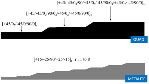
The estimated weight saving is 17.68%. The I* values for Metalite laminates range from 0.019 for r = 1 to 0.002 for r = 8, with an average I* of 0.003. Since Metalite laminates are a repetition of simple sequences, it makes its manufacturing easier than long and complex quad layups.
Cross-ply antisymmetric laminates embedded with shape memory alloy wires have the potential to enhance the sound quality of vibroacoustics by leveraging the special superelasticity, temperature phase transition, and pre-deformation characteristics of shape memory alloys or SMA [Citation82]. The Metalite [0/90/0/90/0] is particularly promising for its ability to adjust mode frequency and alter sound radiation characteristics [Citation83]. This type of cross-ply antisymmetric composite laminate integrates SMA into the laminate matrix material [Citation84]. This approach allows effective tuning of composite elastic modulus properties [Citation85–88] and expands the design range of material structural modulus through SMA material composition and tensile pre-strain design [Citation89–91]. Thus, adjusting the mode frequency of SMA composite laminates can mitigate structural resonance, reduce vibration and sound radiation of composite plates, and enhance the sound quality of composite laminates.
6-ply laminates
For 6-ply laminates, cross-ply laminates are located at ξ2A=1 and ξ1A=1, 0.33, −0.33, −1. The associated cross-ply laminates are [0]6, [0/90/0/0/90/0], [90/0/90/90/0/90] and [90]6, respectively. Unlike previous laminates, the Metalite feasible domain for 6-ply laminates forms a continuous surface covering a significant portion of the Hard 1 and Hard 2 triangular areas ().
Figure 7. Feasible domain of 6-ply Metalite (green) and quad(pink) laminates.
Metalite 6-ply laminates follow the design sequence: [+ϕ1/-ϕ2/+ϕ3/-ϕ3/+ϕ2/-ϕ1]. lists various angles of this sequence and their corresponding I* values, all of which are below 0.02. The material used is IM7/8552.
Table 6. Various values of ϕ1, ϕ2 and ϕ3 and their corresponding I* values.
Using a thin ply of 0.035 mm, the thickness of the laminate in this case is 0.210 mm.
7-ply laminates
For 7-ply laminates, cross-ply laminates are located ξ2A=1 and ξ1A=1, 0.714, 0.428 0.142, −0.142, −0.428, −0.714, −1. The associated cross-ply laminates are [0]7, [0/0/0/90/0/0/0], [0/90/0/0/0/90/0], [0/90/0/90/0/90/0], [90/0/90/0/90/0/90], [90/0/90/90/90/0/90], [90/90/90/0/90/90/90] and [90]7, respectively. There are multiple locations for 0 and 90 degree plies from the 3rd to 6th laminates. illustrates the Metalite feasible domain (green), covering a large portion of the quad space (pink), along with two broad bands on either side of the graph.
Figure 8. Feasible domain of 7-ply Metalite (green) and quad(pink) laminates. The red star indicates a specific example location.
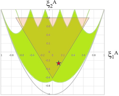
Using a 0.035 mm thin-ply, the thickness of the laminate in this case is 0.245 mm. As an example of converting a quad to Metalite, consider the following soft laminate:
[(+45/-45)2/02/+45/-45/90/(+45/-45)2/02/(+45/-45)2/90/0/+45/0/-45/90/+45/-45/0]s. Conversion to Metalite results in: [+35/-35/-65/0/+65/+35/-35]8.
The matrices [A*] in GPa for the quad and the converted Metalite are very close. The material used is IM7/8552.
shows their failure envelopes using the Omni Failure Criterion [Citation81], indicating very similar performance.
Figure 9. First ply Failure (blue) and the last ply Failure (red) for quad envelopes (left) and Metalite (right) using the omni failure criterion [Citation85]. units: MPa.
![Figure 9. First ply Failure (blue) and the last ply Failure (red) for quad envelopes (left) and Metalite (right) using the omni failure criterion [Citation85]. units: MPa.](/cms/asset/256721b3-483f-4b8e-b2ae-fef5b45288ee/umcm_a_2378369_f0009_c.jpg)
depicts tapered quad and Metalite laminates for a tensile stress increasing linearly from σmin=0 to σmax= σI * h (MN/m).
Figure 10. Tapered quad and Metalite laminates for a tensile stress of 0 degrees increasing linearly from σmin=0 to σmax= σI * h. Above: quad, below: Metalite.
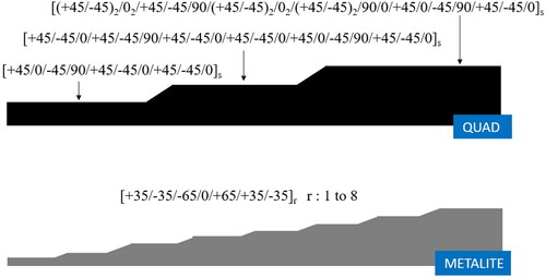
The estimated weight saving is 17.10%. I* values for Metalite laminates range from 0.016 for r = 1 to 0.002 for r = 8, with an average I* of 0.003.
8-ply laminates
For 8-ply laminates, cross-ply laminates are located at ξ2A=1 and ξ1A=1, 0.5, 0, −0.5, −1. The associated cross-ply laminates are [0]8, [0/0/0/90/90/0/0/0], [0/0/90/90/90/90/0/0], [0/90/90/90/90/90/90/0] and [90]8. There are multiple locations for 0 and 90 degree plies on the 2nd through 4th laminates. displays the Metalite feasible domain (green), covering a significant portion of the quad space (pink), with additional broad bands on either side of the graph.
Figure 11. Feasible domains of 8-ply Metalite (green) and quad(pink) laminates.
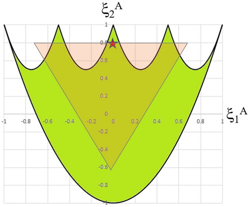
As an example of converting a quad to Metalite, consider the following neutral laminate: [+45/03/903/03/902/02/902/-45/902/0]s. Conversion to Metalite results in: [+10/-10/+80/-80/+80/-80/+10/-10]5.
The matrices [A*] in GPa for the quad and the converted Metalite are alike. The material used is IM7/8552.
illustrates their failure envelopes using the Omni Failure Criterion [Citation81], indicating close similarity.
Figure 12. First ply Failure (blue) and last ply Failure (red) for quad envelopes (left) and Metalite (right) using the omni failure criterion [Citation85]. units: MPa.
![Figure 12. First ply Failure (blue) and last ply Failure (red) for quad envelopes (left) and Metalite (right) using the omni failure criterion [Citation85]. units: MPa.](/cms/asset/dbcc9592-6938-49c0-812d-4686e0317d73/umcm_a_2378369_f0012_c.jpg)
depicts tapered quad and Metalite laminates for a tensile stress increasing linearly from σmin=0 to σmax= σI * h (MN/m).
Figure 13. Tapered quad and Metalite laminates for a tensile stress of 0 degrees increasing linearly from σmin=0 to σmax= σI * h. Above: quad, below: Metalite.
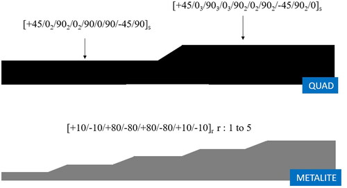
The estimated weight saving is 25%. I* values for Metalite laminates range from 0.009 for r = 1 to 0.001 for r = 5, with an average I* of 0.004.
Whole feasible space of 6, 7 and 8 ply Metalite laminates
illustrates the whole feasible space of Metalite laminates with 6, 7 and 8 plies (green) and quads (pink). This Metalite domain covers nearly the entire feasible space of quads and most of the laminate parameter plot, a unique property compared to other laminates which typically have smaller feasible domains with a greater number of plies. For instance, the feasible domain of 8 to 20-ply quads forms a triangle with vertices at (0.6, 0.6), (-0.6, 0.6), and (0, −0.6) (). Previous studies have shown that many different laminates exhibit large uncovered areas in their feasible domains [Citation7,Citation16], highlighting the uniqueness of Metalite laminates.
Figure 14. Whole feasible space of Metalite laminates with 6, 7, and 8 plies (green) and quads (pink).
Hybridization of Metalite laminates
Metalite laminates can be hybridized while maintaining their properties, facilitating the design of composite materials with different fibers for various applications, including those requiring zero or negative CTE. One example is a hybrid laminate with a carbon/glass ratio of 1:1 to 3:1, which can achieve varying CTE, including negative values. This property is crucial for applications like satellite structures, where dimensional stability over a wide temperature range is essential. Unlike traditional methods that rely on cooling for interference fit [Citation92], Metalite laminates enable easier dimension adjustments through heating, potentially eliminating the need for mechanical joints or adhesives.
Experimental validation at NASA Marshall Space Flight Center, Huntsville, Alabama, has confirmed the negative CTE values in a carbon/quartz hybrid laminate. presents the properties of the materials used, including elastic properties and CTE
Table 7. Carbon and quartz fiber prepreg properties.
The sequence used was [+20c/+20q/+20c/-20c/-20q/-20c/-20c/-20q/-20c/+20c/+20q/+20c/-20c/-20q/-20c/+20c/+20q/+20c/+20c/+20q/+20c/-20c/-20q/-20c], where ‘c’ and ‘q’ denote carbon and quartz plies, respectively. The ply thickness was 0.0635 mm and the carbon/quartz volume fraction was 3:1.
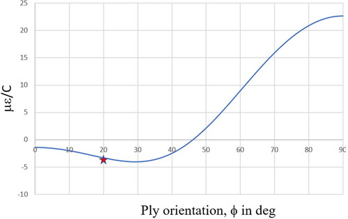
depicts the CTE/ply orientation graph for the carbon/quartz hybrid, showing a range where CTE is negative for 0 ≤ ϕ < 45°, and zero CTE at ϕ = 45°. The experimental results align well with theoretical predictions.
Figure 15. CTE/ply orientation graph for carbon/quartz hybrid. Theoretical results in blue, experimental result in red.
A similar approach using carbon/glass hybrids allows for tuning CTE to achieve zero CTE ply orientations. outlines the properties of carbon and glass fiber prepregs used, including elastic properties and CTE.
Table 8. Carbon and glass fiber prepreg properties.
The sequence used was [+ϕc/+ϕg/+ϕc/-ϕc/-ϕg/-ϕc/-ϕc/-ϕg/-ϕc/+ϕc/+ϕg/+ϕc/-ϕc/-ϕg/-ϕc/+ϕc/+ϕg/+ϕc/+ϕc/+ϕg/+ϕc/-ϕc/-ϕg/-ϕc], where ‘c’ and ‘g’ denote carbon and glass plies, respectively. The ply thickness was 0.125 mm and the carbon/glass volume fractions used were 1:1, 3:1, and 5:1.
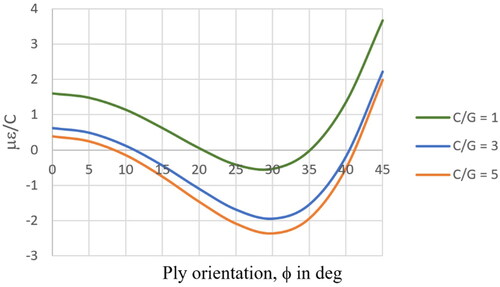
illustrates the CTE/ply orientation graph for the carbon/glass hybrid, demonstrating the ability to tune CTE to zero or negative values by adjusting the carbon/glass fraction and ply orientation (ϕ). This tunability extends beyond CTE optimization, influencing stiffness and strength properties, which differs from quads that require ply additions or removals at fixed orientations (0°, 90°, ±45°).
Figure 16. CTE/ply orientation graph for carbon/glass hybrid.
Zero CTE is important for applications where extreme temperatures occur, such as space. Large negative CTE values, such as those obtained in and , are of interest for interference fit joints [Citation92]. By heating or cooling cylindrical components with positive and negative CTEs it is possible to make bondless-fastenerless joints.
Conclusions
Metalite laminates are exceptionally thin, with 3-ply laminates measuring only 0.105 mm in thickness using thin plies. Even 8-ply laminates remain thin at 0.245 mm with thin plies. This thinness allows Metalite laminates to replace quads with significant weight savings through ply-drops. Under linearly increasing tensile stress conditions, weight savings range from 17% to 25% compared to quads using hard, soft, and neutral laminates. Unlike quads, which represent a collection of discrete dots in feasible space, Metalite laminates occupy a continuous and large surface, enhancing design flexibility. Since Metalite laminates are a repetition of simple sequences, it makes its manufacturing easier than long and complex quad layups.
The whole feasible space of 6, 7 and 8-ply Metalite laminates covers a unique and extensive area of the lamination parameter plot with minimal plies, distinguishing them from other laminates. Additionally, Metalite laminates offer the ability to tailor CTE through hybridization, making them suitable for applications requiring zero or negative CTE, such as space and interference fit applications, respectively. By heating or cooling cylindrical components with positive and negative CTEs it is possible to make bondless-fastenerless joints.
Metalite laminates are also promising for applications in piezoelectric materials for sensors and actuators, as well as in composite plates with embedded shape memory alloy wires for vibration control and sound radiation reduction. Experimental evidence suggests that Metalite laminates with I* = 0 exhibit superior damage tolerance compared to symmetrical laminates, indicating a potential broad applicability of this property for I* < 0.02.
Acknowledgments
Special thanks to Dr. Juan M. Mejia-Ariza from Jet Propulsion Laboratory, NASA, for fabricating the hybrid material panel, Dr. Alan Nettles from NASA Marshall Space Flight Center for conducting the CTE tests, and Dr. Stephen W. Tsai from Stanford University for his contributions to the test plan design.
Disclosure statement
No potential conflict of interest was reported by the author(s).
Data and materials availability
All data needed to evaluate the conclusions are present in the paper.
References
- J.N. Reddy and A. Miravete, Practical Analysis of Composite Structures, CRC Press, Boca Raton, 1995.
- A.A. Baker, and M.L. Scott, Composite Materials for Aircraft Structures. 3rd ed., AIAA Education Series, Reston, VA, 2016.
- S.W. Tsai, and A. Miravete, Design and Analysis of Composite Materials. Reverte Press, Barcelona, 1988. (In Spanish).
- C.T. Herakovich, Mechanics of composites: a historical review, Mech. Res. Commun., vol. 41, pp. 1–20, Apr. 2012. DOI: 10.1016/j.mechrescom.2012.01.006.
- M.M. Abdalla, C. Kassapoglou, and Z. Gürdal, Formulation of Composite Laminate Robustness Constraint in Lamination Parameters Space, AIAA/ASME/ASCE/AHS/ASC Structures, Structural Dynamics and Materials Conference, AIAA Paper 2009-2478, May 2009, pp. 1–15. DOI: 10.2514/6.2009-2478.
- F.X. Irisarri, D.H. Bassir, N. Carrere, and J.F. Maire, Multiobjective stacking sequence optimization for laminated composite structures, Compos. Sci. Technol., vol. 69, no. 7–8, pp. 983–990, 2009. DOI: 10.1016/j.compscitech.2009.01.011.
- A. Miravete, Preferred stacking sequences for homogenization. In: Simplifying the Design and Manufacture of Composite Laminates, Stanford University, RMIT University, Queen’s University Belfast, 2023.
- D. Liu, V.V. Toropov, D.C. Barton, and O.M. Querin, Weight and mechanical performance optimization of blended composite wing panels using lamination parameters, Struct. Multidisc. Optim., vol. 52, no. 3, pp. 549–562, 2015. DOI: 10.1007/s00158-015-1244-x.
- T. Macquart, M.T. Bordogna, P. Lancelot, and R. de Breuker, Derivation and application of blending constraints in lamination parameter space for composite optimisation, Compos. Struct., vol. 135, pp. 224–235, 2016. DOI: 10.1016/j.compstruct.2015.09.016.
- T. Macquart, N. Werter, and R. de Breuker, Aeroelastic design of blended composite structures using lamination parameters, J. Aircraft., vol. 54, no. 2, pp. 561–571, 2017. DOI: 10.2514/1.C033859.
- M.T. Bordogna, P. Lancelot, D. Bettebghor, and R. de Breuker, Static and dynamic aeroelastic tailoring with composite blending and manoeuvre load alleviation, Struct. Multidisc. Optim., vol. 61, no. 5, pp. 2193–2216, 2020. DOI: 10.1007/s00158-019-02446-w.
- Y.M. Meddaikar, F.-X. Irisarri, and M.M. Abdalla, Laminate optimization of blended composite structures using a modified Shepard’s method and stacking sequence tables, Struct. Multidisc. Optim., vol. 55, no. 2, pp. 535–546, 2017. DOI: 10.1007/s00158-016-1508-0.
- S.T. Jsselmuiden, M.M. Abdalla, O. Seresta, and Z. Gürdal, Multi-step blended stacking sequence design of panel assemblies with buckling constraints, Compos. Part B: Engin., vol. 40, no. 4, pp. 329–336, 2009. DOI: 10.1016/j.compositesb.2008.12.002.
- D.W. Radford, and R.J. Diefendorf, Shape instabilities in composites resulting from laminate anisotropy, J. Reinf. Plast. Compos., vol. 12, no. 1, pp. 58–75, 1993. DOI: 10.1177/073168449301200104.
- S. Yan, M. Matveev, and N. Warrior, Process-induced distortion prediction for laminated composites, Proceedings of Twenty-Third International Conference on Composite Materials (ICCM23), Belfast, 30 July–4 August, 2023.
- A. Miravete, Lamination parameter plots. In: Proceedings of Composites Design Workshop XXVI, Stanford University, Palo Alto, CA, 22–26, 2024.
- R.M. Jones, Mechanics of Composite Materials, 2nd ed., Taylor & Francis, Inc., Boca Raton, FA, 1999.
- G. Caprino, and I. Crivelli-Visconti, A note on specially orthotropic laminates, J. Compos. Mater., vol. 16, no. 5, pp. 395–399, 1982. DOI: 10.1177/002199838201600504.
- H. Fukunaga, and G.N. Vanderplaats, Stiffness optimization of orthotropic laminated composites using lamination parameters, AIAA J., vol. 29, no. 4, pp. 641–646, 1991. DOI: 10.2514/3.59931.
- P. Bartholomew, Ply stacking sequences for laminated plates having in-plane and bending orthotropy, Royal Aircraft Establishment Technical Report No. 76003, 1976.
- P. Bartholomew, Ply stacking sequences for laminated plates having in-plane and bending orthotropy, Fibre Sci. Technol., vol. 10, no. 4, pp. 239–253, 1977. DOI: 10.1016/0015-0568(77)90001-X.
- Engineering Sciences Data Unit, Laminate stacking sequences for special orthotropy (Application to fibre reinforced composites), ESDU Item No. 82013, 1982.
- J.W. Gunnink, A note on specially orthotropic laminates - comment, J. Compos. Mater., vol. 17, no. 6, pp. 508–510, 1983. DOI: 10.1177/002199838301700603.
- H. Fukunaga, H. Sekine, M. Sato, and A. Iino, Buckling design of symmetrically laminated plates using lamination parameters, Comput. Struct., vol. 57, no. 4, pp. 643–649, 1995. DOI: 10.1016/0045-7949(95)00050-Q.
- T.A. Fletcher, R. Butler, and T.J. Dodwell, Anti-symmetric laminates for improved consolidation and reduced warp of tapered C-sections, Adv. Manufacturing: Polymer & Compos. Sci., vol. 1, no. 2, pp. 105–111, 2015. DOI: 10.1179/2055035914Y.0000000010.
- T.A. Fletcher, R. Butler, T.J. Dodwell, and S. Erland, Non-symmetric stacking sequences to aid manufacture, Proceedings of 16th European Conference on Composite Materials, Seville, Spain, 22–26 June, 2014.
- E. Valot, Anisotropie du Comportement _a Rupture de Composites _a Structure Isotrope (Anisotropy of Failure Behaviour of Composites with Isotropic Structure), PhD University of Burgundy, France, 2002.
- P. Vannucci, and G. Verchery, A special class of uncoupled and quasihomogeneous laminates, Compos. Sci. Technol., vol. 61, no. 10, pp. 1465–1473, 2001. DOI: 10.1016/S0266-3538(01)00039-2.
- M. Grédiac, On the stiffness design of thin woven composites, Compos. Struct., vol. 51, no. 3, pp. 245–255, 2001. DOI: 10.1016/S0263-8223(00)00135-5.
- M. Grediac, On the design of some particular orthotropic plates with non-standard ply orientations, J. Compos. Mater., vol. 34, no. 19, pp. 1665–1693, 2000. DOI: 10.1106/V4U2-LTQE-Q1JG-3WN2.
- E. Valot, and P. Vannucci, Some exact solutions for fully orthotropic laminates, Compos. Struct., vol. 69, no. 2, pp. 157–166, 2005. DOI: 10.1016/j.compstruct.2004.06.007.
- C.B. York, Buckling interaction in regular arrays of rigidly supported composite laminated plates with orthogrid, isogrid and anisogrid planform, J. Am. Helicopter Society., vol. 52, no. 4, pp. 343–359, 2007. DOI: 10.4050/JAHS.52.343.
- C.B. York, Characterization of nonsymmetric forms of fully orthotropic laminates, J. Aircraft., vol. 46, no. 4, pp. 1114–1125, 2009. DOI: 10.2514/1.32938.
- N. Baker, R. Butler, and C.B. York, Damage tolerance of fully orthotropic laminates in compression, Compos. Technol., vol. 72, no. 10, pp. 1083–1089, 2012. DOI: 10.1016/j.compscitech.2011.09.010.
- N. Baker, and R. Butler, Compression after impact modeling of damage tolerant composite laminates, Proceedings of Conference: 51st AIAA/ASME/ASCE/AHS/ASC Structures, Structural Dynamics, and Materials Conference 18th AIAA/ASME/AHS Adaptive Structures Conference 12th, April, 2010. DOI: 10.2514/6.2010-2868.
- A. Rhead, R. Butler, and C.B. York, Damage tolerance of asymmetric fully orthotropic laminates in compression. Proceedings of 11th Deformation and Fracture of Composites and 5th Structural Integrity and Multi-Scale Modelling Conference, Cambridge, UK, 12–15 Apr, 2011.
- M. P. O’Donnell, and P. M. Weaver, Reconsidering Laminate Non-Symmetry, AIAA J., vol. 58, no. 4, pp. 1–23, 2020.
- B. Vermes, S.W. Tsai, A. Riccio, F. Di Caprio, and S. Roy, Application of the Tsai’s modulus and double-double concepts to the definition of a new affordable design approach for composite laminates, Compos. Struct., vol. 259, no. 1, pp. 113246, 2021. DOI: 10.1016/j.compstruct.2020.113246.
- L.L. Vignoli, R.M.C. Neto, M.A. Savi, P. Pacheco, and A. Kalamkarov, Trace theory applied to composite analysis: a comparison with micromechanical models, Compos. Commun., vol. 25, pp. 100715, 2021. DOI: 10.1016/j.coco.2021.100715.
- S.W. Tsai, A. Arteiro, and J.D. Melo, A Trace-based approach to design for manufacturing of composite laminates, J. Reinf. Plast. Compos., vol. 35, Num. no. 7, pp. 589–600, 2015. DOI: 10.1177/0731684415624770.
- G. Romeo, F. Danzi, and S.W. Tsai, Using Trace to scale the properties of composite materials, JEC Compos. Magazine., vol. 51, no. 88, pp. 42–45, 2014.
- E. Kappel, Unique manufacturing opportunity, book chapter. In: Simplifying the Design and Manufacture of Composite Laminates, Stanford University, RMIT University, Queen’s University Belfast, Belfast, 2023.
- S.W. Tsai, and N.J. Pagano, Invariant properties of composite materials. In: Technical Report., U.S. Air Force Materials Lab, Wright–Patterson AFB, OH, 1968.
- J.L. Grenestedt, and P. Gudmundson, Layup optimization of composite material structures. In: Optimal Design with Advanced Materials, Elsevier, New York, pp. 311–336, 1993.
- K. Svanberg, On Local and Global Minima in Structural Optimization, Proceedings of International Symposium on Optimum Structural Design, 19-22 October, 1981, Tucson, Arizona, pp. 6.3–6.9, 1981.
- M.A. Albazzan, R. Harik, B.F. Tatting, and Z. Gürdal, Efficient design optimization of nonconventional laminated composites using lamination parameters: a state of the art, Compos. Struct., vol. 209, pp. 362–374, 2019. DOI: 10.1016/j.compstruct.2018.10.095.
- T.A. Dutra, and S.F.M. de Almeida, Composite plate stiffness multicriteria optimization using lamination parameters, Compos. Struct., vol. 133, pp. 166–177, 2015. DOI: 10.1016/j.compstruct.2015.07.029.
- P. Jin, X. Zhong, J. Yang, and Z. Sun, Blending design of composite panels with lamination parameters, Aeronaut J., vol. 120, no. 1233, pp. 1710–1725, 2016. DOI: 10.1017/aer.2016.88.
- M. Kameyama, and H. Fukunaga, Optimum design of composite plate wings for aeroelastic characteristics using lamination parameters, Comput. Struct., vol. 85, no. 3–4, pp. 213–224, 2007. DOI: 10.1016/j.compstruc.2006.08.051.
- B. Liu, R.T. Haftka, and P. Trompette, Maximization of buckling loads of composite panels using flexural lamination parameters, Struct. Multidisc. Optim., vol. 26, no. 1–2, pp. 28–36, 2004. DOI: 10.1007/s00158-003-0314-7.
- D. Liu, and V.V. Toropov, A lamination parameter-based strategy for solving an integer-continuous problem arising in composite optimization, Comput. Struct., vol. 128, pp. 170–174, 2013. DOI: 10.1016/j.compstruc.2013.06.003.
- A. Todoroki, and M. Sasai, Stacking sequence optimizations using GA with zoomed response surface on lamination parameters, Adv. Compos. Mater., vol. 11, no. 3, pp. 299–318, 2002. DOI: 10.1163/156855102762506335.
- Y. Xu, J. Zhu, Z. Wu, Y. Cao, Y. Zhao, and W. Zhang, A review on the design of laminated composite structures: constant and variable stiffness design and topology optimization, Adv. Compos. Hybrid Mater., vol. 1, no. 3, pp. 460–477, 2018. DOI: 10.1007/s42114-018-0032-7.
- P. Hao, D. Liu, Y. Wang, X. Liu, B. Wang, G. Li, and S. Feng, Design of manufacturable fiber path for variable-stiffness panels based on lamination parameters, Compos. Struct., vol. 219, pp. 158–169, 2019. DOI: 10.1016/j.compstruct.2019.03.075.
- P.K. Shahabad, M.R. Anamagh, and B. Bediz, Design of laminated conical shells using spectral chebyshev method and lamination parameters, Compos. Struct., vol. 281, pp. 114969, 2022. PaperDOI: 10.1016/j.compstruct.2021.114969.
- J. Zeng, Z. Huang, K. Fan, and W. Wu, An adaptive hierarchical optimization approach for the minimum compliance design of variable stiffness laminates using lamination parameters, Thin. Walled Struct., vol. 157, pp. 107068, 2020. DOI: 10.1016/j.tws.2020.107068.
- G.H.C. Silva, and Y. Meddaikar, Lamination parameters for sandwich and hybrid material composites, AIAA J., vol. 58, no. 10, pp. 4604–4611, 2020. DOI: 10.2514/1.J059093.
- X. Liu, C.A. Featherston, and D. Kennedy, Two-level layup optimization of composite laminate using lamination parameters, Compos. Struct., vol. 211, pp. 337–350, 2019. DOI: 10.1016/j.compstruct.2018.12.054.
- M. Miki, Material design of composite laminates with required in- plane elastic properties. In: Progress in Science and Engineering of Composites, Vol. 2, Japan Soc. for Composite Materials, Tokyo, pp. 1725–1731, 1982.
- M. Miki, Design of Laminated Fibrous Composite Plates with Required Flexural Stiffness, ASTM International, West Conshohocken, PA, pp. 387–400, 1985.
- H. Fukunaga, and H. Sekine, Stiffness design method of symmetric laminates using lamination parameters, AIAA J,., vol. 30, no. 11, pp. 2791–2793, 1992. DOI: 10.2514/3.11304.
- H. Fukunaga, and H. Sekine, A laminate design for elastic properties of symmetric laminates with extension-shear or bending- twisting coupling, J. Compos. Mater., vol. 28, no. 8, pp. 708–731, 1994. DOI: 10.1177/002199839402800802.
- C.G. Diaconu, M. Sato, and H. Sekine, Feasible region in general design space of lamination parameters for laminated composites, AIAA J., vol. 40, no. 3, pp. 559–565, 2002. DOI: 10.2514/2.1683.
- S. Setoodeh, M.M. Abdalla, and Z. Gürdal, Approximate feasible regions for lamination parameters, 11th AIAA/ISSMO Multidisciplinary Analysis and Optimization Conference, vol. 2, pp 814–822, 2006. DOI: 10.2514/6.2006-6973.
- M.W. Bloomfield, C.G. Diaconu, and P.M. Weaver, On feasible regions of lamination parameters for lay-up optimization of laminated composites, Proc. R Soc. A., vol. 465, no. 2104, pp. 1123–1143, 2009. DOI: 10.1098/rspa.2008.0380.
- M.W. Bloomfield, J.E. Herencia, and P.M. Weaver, Analysis and benchmarking of meta-heuristic techniques for lay-up optimization, Comput. Struct., vol. 88, no. 5–6, pp. 272–282, 2010. DOI: 10.1016/j.compstruc.2009.10.007.
- T. Yokozeki, A. Kuroda, A. Yoshimura, T. Ogasawara, and T. Aoki, Damage characterization in thin-ply composite laminates under out-of-plane transverse loads, Compos. Struct., vol. 93, no. 1, pp. 49–57, 2010. DOI: 10.1016/j.compstruct.2010.06.016.
- H. Sasayama, K. Kawabe, S. Tomoda, I. Ohsawa, K. Kageyama, and N. Ogata, Effect of lamina thickness on first ply failure in multidirectionally laminated composites, Proceedings of the 8th Japan International SAMPE Symposium & Exhibition (JISSE-8), Tokyo, Japan, November, 2003.
- H.M. EL-Dessouky, and C.A. Lawrence, Ultra-lightweight carbon fiber/thermoplastic composite material using spread tow technology, Compos. Part B., vol. 50, pp. 91–97, 2013. DOI: 10.1016/j.compositesb.2013.01.026.
- T. Yokozeki, Y. Aoki, and T. Ogasawara, Experimental characterization of strength and damage resistance properties of thin-ply carbon fiber/toughened epoxy laminates, Compos. Struct., vol. 82, no. 3, pp. 382–389, 2008. DOI: 10.1016/j.compstruct.2007.01.015.
- R. Amacher, J. Cugnoni, J. Botsis, L. Sorensen, W. Smith, and C. Dransfeld, Thin-ply composites: experimental characterization and modeling of size-effects, Compos. Sci. Technol., vol. 101, pp. 121–132, 2014. DOI: 10.1016/j.compscitech.2014.06.027.
- J.D. Fuller, and M.R. Wisnom, Pseudo-ductility and damage suppression in thin-ply CFRP angle-ply laminates, Compos. Part A., vol. 69, pp. 64–71, 2015. DOI: 10.1016/j.compositesa.2014.11.004.
- H. Sasayama, K. Kawabe, S. Tomoda, I. Ohsawa, K. Kageyama, and N. Ogata, Effect of lamina thickness on first ply failure in multidirectionally laminated composites, Proceedings of the 8th Japan International SAMPE Symposium & Exhibition (JISSE-8), Tokyo, Japan, 2003.
- K. Yamaguchi, and H.T. Hahn, The improved ply cracking resistance of thin-ply laminates, Proceedings of 15th International Conference on Composite Materials (ICCM-15), Durban, South Africa, 2005.
- M. Ray, and J.N. Reddy, Performance of piezoelectric fiber-reinforced composites for active structural-acoustic control of laminated composite plates, IEEE Trans. Ultrason. Ferroelectr. Freq. Control., vol. 51, no. 11, pp. 1477–1490, 2004. DOI: 10.1109/tuffc.2004.1367489.
- M. Ray, and A. Faye, Active structural-acoustic control of laminated composite plates using vertically/obliquely reinforced 1–3 piezoelectric composite patch, Engin. Int. J. Mech. Mater. Des., vol. 5, no. 2, pp. 123–141, 2009. DOI: 10.1007/s10999-008-9089-8.
- M. Ray, and R. Balaji, Active structural–acoustic control of laminated cylindrical panels using smart damping treatment, Int. J. Mech. Sci., vol. 49, no. 9, pp. 1001–1017, 2007. DOI: 10.1016/j.ijmecsci.2007.02.001.
- M. Ray, A. Faye, S. Patra, and R. Bhattacharyya, Theoretical and experimental investigations on the active structural–acoustic control of a thin plate using a vertically reinforced 1-3 piezoelectric composites, Smart Mater. Struct., vol. 18, no. 1, pp. 015012, 2008. DOI: 10.1088/0964-1726/18/1/015012.
- A.S. Pavan Kumar, S. Panda, and N.H. Reddy, Smart damping of vibration of annular plates by the design of a cylindrically orthotropic piezoelectric fiber-reinforced composite actuator, Acta Mech., vol. 226, no. 9, pp. 3151–3176, 2015. DOI: 10.1007/s00707-015-1363-x.
- S. Panda, and G.G. Sopan, Nonlinear analysis of smart functionally graded annular sector plates using cylindrically orthotropic piezoelectric fiber reinforced composite, Int. J. Mech. Mater. Des., vol. 9, no. 1, pp. 35–53, 2013. DOI: 10.1007/s10999-012-9204-8.
- S.W. Tsai, and J.D. Melo, A unit circle failure criterion for carbon fiber reinforced polymer composites, Compos. Sci. Technol., vol. 123, pp. 71–78, 2016. DOI: 10.1016/j.compscitech.2015.12.011.
- L. Verma, J.J. Jefferson, S.M. Sivakumar, G. Balaganesan, S. Vedantam, and H.N. Dhakal, Evaluation of quasi-static indentation response of superelastic shape memory alloy embedded GFRP laminates using AE monitoring, Polym. Test., vol. 93, pp. 106942, 2021. DOI: 10.1016/j.polymertesting.2020.106942.
- Y. Huang, J. Hu, J. Wang, J. Sun, Y. You, Q. Huang, and E. Xu, Sound quality performance of orthogonal antisymmetric composite laminates embedded with SMA wires, Materials., vol. 16, no. 9, pp. 3570, 2023. DOI: 10.3390/ma16093570.
- M. Sattari, M. Kadkhodaei, S. Akbarzadeh, R. Gholami, and A. Beheshti, Wear in superelastic shape memory alloys: A thermomechanical analysis, Wear., vol. 488–489, pp. 204139, 2022. DOI: 10.1016/j.wear.2021.204139.
- M. Sun, M. Chang, Z. Wang, H. Li, and X. Sun, Experimental and simulation study of low-velocity impact on glass fiber composite laminates with reinforcing shape memory alloys at different layer positions, Appl. Sci., vol. 8, no. 12, pp. 2405, 2018. DOI: 10.3390/app8122405.
- Y. Liu, Z. Wang, H. Li, M. Sun, F. Wang, and B. Chen, Influence of embedding SMA fibres and SMA fibre surface modification on the mechanical performance of BFRP composite laminates, Materials., vol. 11, no. 1, pp. 70, 2018. DOI: 10.3390/ma11010070.
- K. Pazhanivel, G.B. Bhaskar, A. Elayaperumal, P. Anandan, and S. Arunachalam, Influence of SMA reinforcement on the impact resistance of GFRP composite laminates under different temperatures, Bull. Mater. Sci., vol. 39, no. 3, pp. 889–899, 2016. DOI: 10.1007/s12034-016-1201-3.
- S. Zhao, J. Teng, Z. Wang, X. Sun, and B. Yang, Investigation on the mechanical properties of SMA/GF/epoxy hybrid composite laminates: flexural, impact, and interfacial shear performance, Materials., vol. 11, no. 2, pp. 246, 2018. DOI: 10.3390/ma11020246.
- H. Lei, Z. Wang, L. Tong, and X. Tang, Macroscopic mechanical characterization of SMAs fiber-reinforced hybrid composite under uniaxial loading, J. Mater. Eng. Perform., vol. 22, no. 10, pp. 3055–3062, 2013. DOI: 10.1007/s11665-013-0584-1.
- M. Sun, M. Chang, Z. Wang, H. Li, and Y. Liu, Simulation of eccentric impact of square and rectangular composite laminates embedded with SMA, Materials., vol. 11, no. 12, pp. 2371, 2018. DOI: 10.3390/ma11122371.
- J. Qiu, and I. Stiharu, Vibration and noise reduction of pipelines using shape memory alloy, Sci. Engin. Compos. Mater., vol. 29, no. 1, pp. 165–175, 2022. DOI: 10.1515/secm-2022-0015.
- R. Mott, Machine Elements in Mechanical Design, 5th ed., Pearson Publisher, New York NY, 2013.