Abstract
Objective: Due to the rolling manufacturing process, most advanced high-strength steels (AHSS) demonstrate in-plane anisotropic material behavior. This study investigates the effects of material orientation on the axial crush behavior and fracture of AHSS with axial crush tests and computer simulations.
Methods: Crush simulation models considering material anisotropy and damage evolution were developed in LS-DYNA based on the drop-tower crush test results and coupon characterization test data for DP780 steel. The modified Mohr-Coulomb (MMC) isotropic fracture model was employed in the crush simulation models for fracture prediction.
Results: The 12-sided components fabricated in the transverse (T) direction of the sheet exhibited slightly higher crush loads and reduced crush distances compared to those in the longitudinal (L) direction. The crush behavior in each direction was generally proportional to ultimate tensile strength. All of the materials investigated in this study showed some cracking in the crush tests for both component orientations, but only DP780 showed significant anisotropy in fracture behavior with more cracking for the T direction compared to the L direction. Overall, the amount of cracking observed in the tests had little or no significant effect on the axial crush performance. The MMC fracture loci in both the L and T directions were determined using a reverse engineering approach, and the stress–strain curves beyond the uniform elongation point were extended using an optimization method. Both material models MAT103 and MAT224 predicted the crush and fracture behavior with reasonably good accuracy.
Conclusions: The predicted fracture mode and force–displacement curves agreed well with the test data for both the L and T directions in axial crush tests of the 12-sided components. The simple isotropic material model MAT224 is adequate for crush simulations to predict material orientation effects on AHSS component crush performance and fracture behavior.
Introduction
Advanced high-strength steels (AHSS) are widely utilized in the automotive industry to help balance vehicle weight targets and stringent vehicle crash standards. Combined with the efficient use of geometry and load paths through topology and shape optimization, AHSS has enabled vehicle manufacturers to achieve lightweight vehicle designs while complying with stringent safety regulations. For example, optimized roof structures enable compliance with the new FMVSS 216 roof strength regulation without significantly increasing vehicle mass via the comprehensive usage of AHSS such as dual-phase (DP) steels, transformation-induced plasticity (TRIP) steels, and hot-stamping boron steel (A/SP 2009; Chen Citation2010). The FutureSteelVehicle (FSV) program recently developed by WorldAutoSteel features optimized AHSS body structure concepts for compact electrified vehicles in the 2015 to 2020 model years (Shaw et al. Citation2011). The optimized steel body structure concepts showed the potential to reduce vehicle mass by more than 35 percent over a benchmark vehicle and meet the projected 2020 safety regulations while reducing total life cycle vehicle emissions. A study on North American light vehicle metallic material trends (Schultz and Abraham Citation2009) showed that AHSS utilization in new automobiles will grow by 10 percent annually and may reach over 204 kg per vehicle by 2020, and it is expected that AHSS will be used approximately 3 times more frequently than current levels by 2020 in North American light vehicle body structures.
Though the increased usage of AHSS can result in weight savings, one performance parameter to be studied is fracture during a dynamic loading event such as a vehicle crash. With lower ductility compared to conventional steels, AHSS can be relatively prone to fracture during dynamic loading, and the fracture behavior of AHSS components has to be considered in vehicle crash simulations to achieve a reliable prediction. Crash simulations that do not take into account the fracture behavior may overstate the load-carrying capacity and the absorbed energy of a structural component. In a previous study (Chen et al. Citation2011) on 3 material models available in LS-DYNA (Livermore Software Technology Corporation, Livermore, CA), it was shown that the modified Mohr-Coulomb (MMC) fracture model (Bai and Wierzbicki Citation2008), developed under the assumption of in-plane isotropy, performed reasonably well in fracture predictions for both bending and axial component crush tests.
The rolling manufacturing process to produce AHSS sheets may introduce in-plane anisotropic material behavior; that is, the mechanical properties in the rolling direction (longitudinal, L) are different from those in the perpendicular (transverse, T) direction. Studies show that local formability such as shear fracture and edge cracking of AHSS depends upon the material orientation (Chiriac 2010; Shih et al. 2010a,b). For example, Shih et al. (2010a) observed that the shear fracture limit is higher when the bending axis is perpendicular to the rolling direction of the sheet than when the bending axis is parallel to the rolling direction, particularly for the grades with higher strength such as DP780 and DP980. An AHSS part made in the preferred orientation for better local formability may not be a preferred orientation under crush loads depending upon the loading direction. In this study, the effects of material orientation on the axial crush behavior and fracture of AHSS were investigated using six different AHSS with both longitudinal and transverse orientations parallel to the axial crush direction in the drop-tower crush tests.
So far, there has been little information in the open literature on modeling the material anisotropy of ductile fracture of AHSS in dynamic loading. Anisotropic fracture models are still under development and not yet available in commercial finite element codes such as LS-DYNA or ABAQUS (Dassault Systèmes Simulia Corporation, Providence, RI). Therefore, the isotropic MMC fracture model was extended in this study to model the material orientation effects on AHSS crush and fracture behavior. The drop-tower crush test results and coupon characterization test data were then employed to develop crush simulation models in LS-DYNA considering the material anisotropy and the damage evolution.
Table 1 Steel grades and material properties in L and T directions.
Axial Crush Test
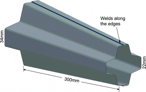
Based on the cross-section optimization results in a previous study (Chen et al. Citation2009), a tapered part with a 12-sided cross section was designed as shown in . The 12-sided design demonstrated enhanced axial crush energy absorption capability to other geometries shown in previous studies by Chen et al. (Citation2009, Citation2010). In axial crush testing, the energy absorption capacity of the 12-sided cross section component is 30 to 60 percent higher than that of the conventional component designs such as octagonal, circular, and hexagonal cross sections of the same mass. When made from AHSS such as DP590 and DP780, the 12-sided component can enable potential weight reduction without sacrificing the axial crush energy absorption performance compared to the conventional components using square or rectangular cross sections made from conventional high strength low alloy HSLA340 steel.
As shown in , the tapered 12-sided component is 300 mm long and has a wall width of 22 mm at the front and 34 mm at the back, resulting in a longitudinal taper angle of approximately 4°. The components were fabricated by press brake forming 2 individual halves and then gas metal arc single-lap welding. The components were made from the sheet steels with longitudinal (L) and transverse (T) orientations parallel to the axial crush direction in the drop-tower crush tests, respectively. Three replicate specimens were tested for each steel grade and sheet orientation. The impact velocity was approximately 7.3 m/s with a total energy of 12.1 kJ. All of the kinetic energy was absorbed by the components during crush testing. The crush forces and distances were measured to compare performance.
Six high-strength steels at a gauge of approximately 1.0 mm were selected to make the 12-sided components. As shown in , the steel grades include conventional high-strength low-alloy steel HSLA340 and AHSS with minimum tensile strengths up to 780 MPa. DP590IBF is a dual-phase steel with improved bending and flanging (IBF) performance, which has a more refined and homogenous microstructure than the conventional DP590. Similarly, DP780IBF has improved bending and flanging capability with a more refined and homogenous microstructure compared to the conventional DP780. TRIP780 is a transformation-induced plasticity steel with a minimum tensile strength of 780 MPa. During deformation, the retained austenite in TRIP steels progressively transforms to martensite, thereby increasing the work hardening rate (n value) with increasing values of strain, which provides an advantage over dual-phase steels with similar tensile strengths in some severe stretch-forming applications.
shows the mechanical properties of the 6 different grades of steel in both the L and T directions, as obtained from uniaxial tension tests. Differences in tensile strength and ductility were observed between the L and T directions. Except for TRIP780, the true fracture strain in the T direction was lower than that in the L direction. DP780 demonstrated the greatest anisotropic behavior with the true fracture strain in the T direction 26 percent lower than that in the L direction. DP590IBF and DP780IBF showed less anisotropy than DP590 and DP780, respectively.
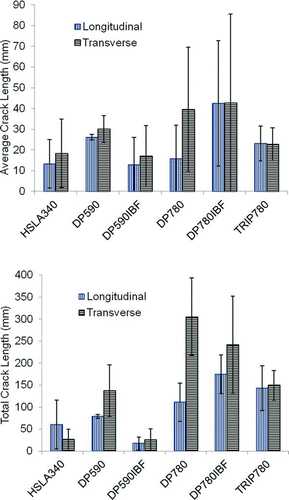
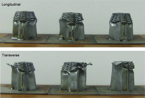
In the drop-tower tests, the tapered 12-sided components exhibited relatively stable axial crush behavior with some cracking observed in all materials. The cracking behavior was characterized for each crushed component, and the average and the total crack lengths for each material and orientation are shown in . Based on the total crack length per test specimen, HSLA340 and DP590IBF showed the least cracking, DP590 and TRIP780 showed intermediate cracking, and DP780 and DP780IBF showed the most cracking. At a given strength level, there appears to be an advantage of DP590IBF over DP590 and TRIP780 over DP780 and DP780IBF in terms of cracking resistance. Except in DP590IBF, the dual-phase steels showed some anisotropy in cracking behavior with a tendency for more cracking in specimens with a transverse orientation. This was especially true for DP780, which exhibited the most anisotropy in cracking behavior.
The performance in terms of average crush load and distance is compared in , in which all values represent averages of the 3 replicate tests. As the tensile strength increased, the average crush load increased and the corresponding crush distance decreased to absorb the same amount of energy. The average crush load for TRIP780 was significantly higher than those of DP780 and DP780IBF because of its thicker gauge. Although more cracking was observed in the crushed components in the T direction, the amount of cracking appeared to have little or no significant effect on the overall performance. The data in show that for the same steel grade the components made in the T direction showed a slightly higher crush load and a shorter crush distance despite the tendency for increased cracking in this orientation. The higher strength in the T direction, as shown in , is more important than cracking behavior in determining crush performance in these tests. The crush behavior in each direction was generally proportional to ultimate tensile strength.
Table 2 Comparison of crush load and crush distance
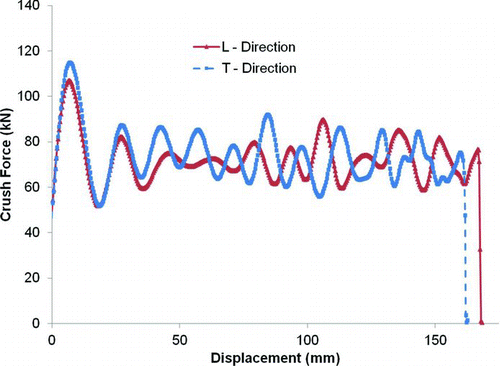
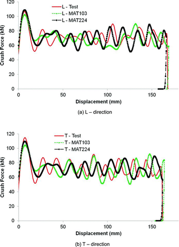
The measured force–displacement curves (averaged from 3 crush tests) from both L and T components for DP780 are shown in . The T components showed slightly higher initial peak loads and average crush loads and lower crush distances than those of the L components.
Among these materials, a significant difference in fracture behavior between the L and T directions was only observed in DP780 during axial crush testing. Therefore, the modeling study of the material orientation effects on crush and fracture behavior was focused only on DP780. The force–displacement curves and the deformation modes shown in and were used to assess the capabilities of various material models considering the orientation effect in the simulations.
Material Model and Fracture Locus
Two plasticity material models in LS-DYNA were selected in this study: MAT224 (MAT_TABULATED_JOHNSON_ COOK), a von-Mises yield function with an isotropic hardening rule, and MAT103 (MAT_ANISOTROPIC_ VISOPLASTIC), an anisotropic–viscoplastic material model. Because MAT103 uses an anisotropic yield criterion proposed by Hill (Citation1948), anisotropy coefficients r 0, r 45, and r 90 measured in the 0, 45, and 90° direction from the rolling direction are needed.
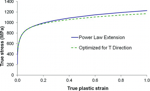
The true stress–true plastic strain curve obtained from the uniaxial tension test was used in the simulations. The measured stress–strain curve is valid only up to the point of uniform elongation, beyond which diffuse necking begins to develop, followed by localized necking and eventual fracture. Usually power law curve fitting using the terminal n value was used to extend the stress–strain curve of DP780 to higher strain values well beyond the uniform elongation point, as shown in for the transverse direction. The load curves obtained from the uniaxial tension test and from the simulation using power law fitting of the stress–strain curve are compared in . It shows that the strain localization followed by load drop was delayed in the simulation due to its high work hardening rate from power law fitting.
Fig. 5 Optimization of the extension of stress–strain curve in the transverse direction (color figure available online).
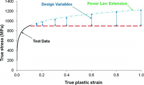
Fig. 6 Load curves from uniaxial tension tests on DP780 in the transverse direction (color figure available online).
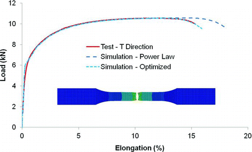
To obtain an appropriate extension of the stress–strain curve, a simple optimization model was set up using optimization software HyperStudy (Altair Engineering, Inc., Troy, MI). As shown in , the design variables were defined as the stress values at a set of specified strains beyond the diffuse necking point. The power law extension was used as the upper bound for the design variables, and the horizontal dashed line with a zero work hardening rate was used as the lower bound. The objective of the optimization was to minimize the difference between the load curves from the measurement and the simulation of the uniaxial tension test. The optimized extension of the stress–strain curve for DP780 is shown in . It shows that when the extension of the stress and strain curve changed from the power law extension to the optimized extension, the predicted load curve from the simulation agreed well with the measured load curve in the tension test in both strain localization and load drop zones, as shown in . Similarly, the stress–strain curve with the optimized extension was obtained for the longitudinal direction. These stress–strain curves with the optimized extension were then used in the crush simulations.
Fig. 7 Optimized extension of the stress–strain curve for DP780 in the transverse direction (color figure available online).
In a previous study by Chen et al. (Citation2011), 3 material fracture models were investigated with actual crush test data for axial and bending loading conditions. It was shown that the MMC fracture model (Bai and Wierzbicki Citation2008) performed reasonably well in fracture predictions for both the bending and axial crush tests. Therefore, the MMC fracture model was employed again in this study.
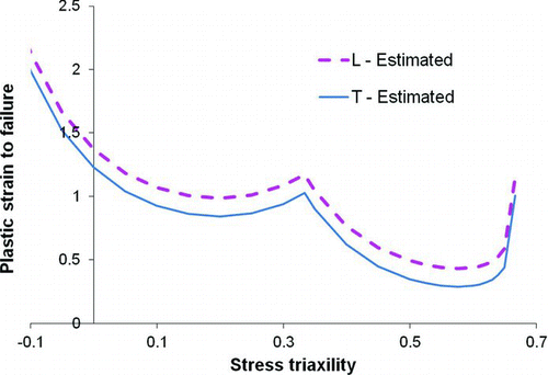
For sheet metals under plane stress conditions, a typical MMC fracture locus is expressed in terms of the plastic strain to failure vs. stress states defined by stress triaxiality, η, or the ratio of the mean stress to the von Mises equivalent stress.
The fracture locus is often used by incorporating a damage parameter D to specify the damage evolution rule when the material is deformed under nonproportional loadings. It is assumed that the damage parameter D is accumulated as a linear function of the increment of the equivalent plastic strain dϵ p normalized with respect to the current value of the fracture locus ϵ f (η) under proportional loading:
The MMC fracture locus was applied directly in MAT224 as a defined curve. In MAT103, the MMC fracture locus was added as the fracture criterion through the use of the input deck *MAT_ADD_EROSION, and the damage accumulation was considered using the GISSMO (Generalized Incremental Stress State dependent damage MOdel) damage model. Only the linear damage accumulation rule was used in this study.
The MMC fracture locus was available for DP780, as reported by Luo et al. (Citation2010). However, because the current DP780 is different from the material reported by Luo et al. (Citation2010), a new fracture locus was needed.
Because there are no anisotropic ductile fracture models available, the MMC fracture locus had to be determined separately in the longitudinal and transverse directions in order to simulate the fracture behavior of the component in each individual direction. In this study, it was assumed that the current DP780 had the same shape of the fracture locus as the DP780 material reported by Luo et al. (Citation2010), but the level of the fracture locus was determined using the fracture strain measured in the uniaxial tension test for the current DP780 material.
The true fracture strain, essentially the local length strain at failure, was obtained using the following equation:
Simulation results
Before the advent of crush simulations, metal-forming simulations were performed for the component made by press brake forming. These forming simulation results (including thickness, plastic strains, and damage values) were then mapped to the crush simulation model to account for the forming effects. Belytschko-Tsay (type 2) shell elements with 5 through-thickness integration points were utilized in all simulations. A 1.0-mm mesh size was used in all simulations, which is consistent with the length scale used in the MMC model parameters calibration (Luo et al. Citation2010). The sensitivity of mesh sizes on fracture predictions can be found in a previous study (Chen et al. Citation2011).
In high-speed dynamic axial crush tests, the strain rate is generally over 100 s−1. The effect of strain rate on the fracture locus or failure limit for AHSS steels is an ongoing research subject with limited available test data. The data by Johnson and Cook (Citation1985) for AISI 4340 steel and other metals showed that the strain rate and temperature effects are less important than the stress state effects. A recent experimental study (Huang et al. Citation2011) on several dual-phase steels including DP780 demonstrated that the strain rate had an insignificant effect on the fracture strain. Therefore, the effect of strain rate on fracture was not considered in this study and the fracture locus shown in was used directly in the dynamic axial crush simulations.
Fig. 10 Comparison of predicted deformation modes for DP780: (a) MAT224, L direction, (b) MAT224, T direction, (c) MAT103, L direction, and (d) MAT103, T direction (color figure available online).
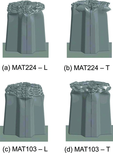
Both material models MAT224 and MAT103 were utilized to simulate the component crush tests for DP780. The stress–strain curves with the optimized extension and the different fracture loci for the L and T directions were used in the corresponding component crush simulations. shows the predicted force–displacement curves using the 2 material models along with the test results for both components made from sheet steels in the L and T directions. Overall, the peak loads, average crush loads, and crush distances predicted by the 2 material models agreed well with the test data. The predicted crush loads were also slightly higher in the T direction with shorter crush distances than those in the L direction. Regarding the selection of yield criterion, the use of an anisotropic yield criterion in material plasticity modeling (MAT103) does not show significant advantages in crush load and distance predictions over the isotropic material model MAT224. In fact, a better correlation with the peak load test data was observed with MAT224 for both test directions.
shows the deformation modes predicted by material models MAT 224 and MAT103 in the L and T directions. Similar to the observations in the crush tests, more severe fracture was predicted in the T direction for both material models. The deformation modes and fracture behavior predicted by both material models correlated reasonably well with the test results shown in . Again, no advantage was observed for MAT103 in the prediction of material fracture behavior, even with approximately 30 percent more computational time than MAT224. Therefore, a material model with an anisotropic yield criterion may not be necessary for crush simulations, and material model MAT224 with isotropic yield criterion, which is relatively fast and reasonably accurate, is adequate for crush simulations to predict AHSS component crush performance and fracture behavior.
Conclusions
The effects of material orientation on the axial crush and fracture behavior of AHSS were investigated using optimized 12-sided components. It was observed from the test data that components fabricated in the T direction of the sheet exhibited slightly higher crush loads and reduced crush distances due to higher tensile strength in the T direction compared to the L direction. The crush behavior in each direction was generally proportional to ultimate tensile strength. All of the materials investigated in this study showed some cracking in the crush tests for both component orientations, but only DP780 showed significant anisotropy in fracture behavior, with more cracking for the T direction compared to the L direction. Overall, the amount of cracking observed in these tests had little or no significant effect on the axial crush performance.
The material orientation effects on the fracture behavior of DP780 were simulated using the material models MAT103 and MAT224 coupled with the isotropic MMC fracture model. The fracture loci in both the L and T directions were determined using a reverse engineering approach, and the stress–strain curves beyond the uniform elongation point were extended using an optimization method. The component crush simulation results showed that both MAT103 and MAT224 predicted the crush and fracture behavior with reasonably good accuracy. The simple isotropic material model MA224 is adequate for crush simulations to predict material orientation effects on AHSS component crush performance and fracture behavior.
Disclaimer
The material in this article is intended for general information only. Any use of it in relation to specific applications should be based on independent examination and verification of its unrestricted availability for such use and determination of suitability for the application by professionally qualified personnel. No license under any patents or other proprietary interest is implied by the publication of this article. Those making use of or relying upon this material assume all risks and liabilities arising from such use or reliance.
Acknowledgments
© Guofei Chen, Todd M. Link, Ming F. Shi, and Tau Tyan
References
- 2009 . Auto/Steel Partnership (A/SP). Mass Efficient Architecture for Roof Strength (MEARS) Phase II Final Report Southfield , MI
- Bai , Y and Wierzbicki , T . 2008 . A new model of metal plasticity and fracture with pressure and lode dependence . Int J. Plast. , 24 ( 6 ) : 1071 – 1096 .
- Chen , G . 2010 . Optimized design solutions for roof strength using advanced high strength steels . SAE Int J Mater Manuf. , 3 ( 1 ) : 90 – 98 .
- Chen , G , Link , T M , Shi , M F , Tyan , T , Gao , R and McKune , P M . 2010 . Axial crash testing and finite element modeling of a 12-sided steel component . SAE Int J Mater Manuf. , 3 ( 1 ) : 162 – 173 .
- Chen , G , Shi , M F and Tyan , T . 2009 . Cross-section optimization for axial and bending crashes using dual phase steels . SAE Int J Mater Manuf. , 1 ( 1 ) : 537 – 547 .
- Chen , G , Shi , M F and Tyan , T . 2011 . Fracture modeling of AHSS in component crush tests . SAE Int J Mater Manuf. , 4 ( 1 ) : 1 – 9 .
- Chiriac , C . 2010 . “ Sheared edge performance of DP780 steels—conventional vs. improved bending and flanging (IBF) steels ” . In Paper presented at: Materials Science and Technology 2010 Book and Exhibition Houston , TX October 17–21
- Hill , R . 1948 . A theory of the yielding and plastic flow of anisotropic metals . Proc R Soc Lond A Math Phys Sci. , 193 : 281 – 297 .
- Huang , G , Yan , B and Zhu , H . The effect of strain rate on tensile properties and fracture strain . Paper presented at: 2011 Great Design in Steel Seminar , Livonia , MI May
- Johnson , G R and Cook , W H . 1985 . Fracture characteristics of three metals subjected to various strains, strain rates, temperatures and pressures . Eng Fract Mech. , 21 : 31 – 48 .
- Luo , M , Chen , X M , Shi , M F and Shih , H C . Numerical analysis of AHSS fracture in a stretch–bending test . Paper presented at: NUMIFORM 2010: Proceedings of the 10th International Conference on Numerical Methods in Industrial Forming Processes Dedicated to Professor O. C. Zienkiewicz (1921–2009) , Pohang, Republic of Korea
- Schultz , R A and Abraham , A K . Metallic material trends for North American light vehicles . Paper presented at: 2009 Great Design in Steel Seminar; May , Livonia , MI
- Shaw , J , Kuriyama , Y and Lambriks , M . 2011 . Achieving a Lightweight and Steel-Intensive Body Structure for Alternative Powertrains Detroit , MI SAE International SAE Paper 2011-01-0425
- Shih , H C , Shi , M F , Zeng , D and Xia , Z C . 2010a . Development of Empirical Shear Fracture Criterion for AHSS Detroit , MI SAE International SAE Paper 2010-01-0977
- Shih , H C , Chiriac , C and Shi , M F . The effects of AHSS shear edge condition on edge fracture . Paper presented at: 2010 International Conference on Manufacturing Science and Engineering , Erie , PA
