Abstract
Objective: The United Nations Economic Commission for Europe Informal Group on GTR No. 7 Phase 2 are working to define a build level for the BioRID II rear impact (whiplash) crash test dummy that ensures repeatable and reproducible performance in a test procedure that has been proposed for future legislation. This includes the specification of dummy hardware, as well as the development of comprehensive certification procedures for the dummy. This study evaluated whether the dummy build level and certification procedures deliver the desired level of repeatability and reproducibility.
Methods: A custom-designed laboratory seat was made using the seat base, back, and head restraint from a production car seat to ensure a representative interface with the dummy. The seat back was reinforced for use in multiple tests and the recliner mechanism was replaced by an external spring–damper mechanism. A total of 65 tests were performed with 6 BioRID IIg dummies using the draft GTR No.7 sled pulse and seating procedure. All dummies were subject to the build, maintenance, and certification procedures defined by the Informal Group.
Results: The test condition was highly repeatable, with a very repeatable pulse, a well-controlled seat back response, and minimal observed degradation of seat foams. The results showed qualitatively reasonable repeatability and reproducibility for the upper torso and head accelerations, as well as for T1 Fx and upper neck Fx . However, reproducibility was not acceptable for T1 and upper neck Fz or for T1 and upper neck My . The Informal Group has not selected injury or seat assessment criteria for use with BioRID II, so it is not known whether these channels would be used in the regulation. However, the ramping-up behavior of the dummy showed poor reproducibility, which would be expected to affect the reproducibility of dummy measurements in general.
Pelvis and spine characteristics were found to significantly influence the dummy measurements for which poor reproducibility was observed. It was also observed that the primary neck response in these tests was flexion, not extension. This correlates well with recent findings from Japan and the United States showing a correlation between neck flexion and injury in accident replication simulations and postmortem human subjects (PMHS) studies, respectively.
Conclusions: The present certification tests may not adequately control front cervical spine bumper characteristics, which are important for neck flexion response. The certification sled test also does not include the pelvis and so cannot be used to control pelvis response and does not substantially load the lumbar bumpers and so does not control these parts of the dummy. The stiffness of all spine bumpers and of the pelvis flesh should be much more tightly controlled. It is recommended that a method for certifying the front cervical bumpers should be developed. Recommendations are also made for tighter tolerance on the input parameters for the existing certification tests.
Introduction
The United Nations (UN) Global Technical Regulation 7— Head Restraints was established on the Global Registry in 2008 (UN Citation2008), following several years of development by the GTR-7 Informal Group under the direction of GRSP and WP.29 in Geneva. GTR-7 2008 is usually referred to as Phase 1 and includes a number of options for static tests of head restraint geometry and a dynamic test of head restraint geometry using the Hybrid III frontal impact crash test dummy. GTR-7 Phase 1 also includes a provision for contracting parties (CPs) to adopt a suitable test procedure using the BioRID II rear impact dummy, provided that the procedure has first been adopted in the CPs national regulations.
The GTR-7 Informal Group is now working on Phase 2, for which the ultimate goal is to develop a dynamic rear impact test procedure and seat performance criteria using the BioRID II dummy that is acceptable to all CPs.
The biofidelity of the BioRID dummy has been assessed by a number of organizations, including the European Enhanced Vehicle-safety Committee (EEVC) and the National Highway Traffic Safety Administration (NHTSA). The EEVC developed a suite of biofidelity requirements based on an assessment of 19 volunteer and postmortem human subjects (PMHS) studies. Biofidelity requirements were defined for 5 low-speed (7–10 km/h) rear impact sled test conditions using rigid and compliant laboratory seats (Hynd et al. Citation2007). A subsequent evaluation of the biofidelity of the BioRID IIg, RID3D, and Hybrid III led to the recommendation that the BioRID IIg was the most biofidelic dummy in these test conditions (Carroll et al. Citation2007). Similarly, the NHTSA developed biofidelity requirements based on moderate-speed (17 and 24 km/h) PMHS tests (Kang et al. Citation2012) using a laboratory seat with a controlled recliner response (Moorhouse et al. Citation2012). The internal and external biofidelity of the BioRID IIg, RID3D, and Hybrid III was evaluated at each test severity using the NHTSA biofidelity ranking system (Rhule et al. Citation2005) and it was reported that overall the BioRID IIg was the most biofidelic dummy at both loading severities.
Moorhouse et al. (Citation2012) also performed at least 3 repeat tests per dummy per test severity, from which preliminary observations on repeatability were reported using the coefficient of variation (CV). The preliminary repeatability results indicated that the BioRID II exhibited good repeatability at both speeds; the Hybrid III exhibited good and acceptable repeatability in the 17 and 24 km/h tests, respectively; and the RID3D demonstrated unacceptable repeatability at both speeds.
Bortenschlager et al. (2009) reported on a series of sled tests to evaluate the repeatability and reproducibility of the BioRID IIg in 16 km/h rear impact sled tests using hard bucket seats from racing cars. These seats were robust enough to allow multiple tests with the same seat and reduced the contribution of seat variability on the evaluation of the dummy, although the seats are much harder than standard production seats. Bortenschlager et al. (2009) reported that the CV for repeatability was generally less than or close to 10 percent except for lower neck Fz , upper neck My , and N km (which uses upper neck My ). The same measurements plus upper neck Fx showed poor reproducibility in the same test conditions.
The BioRID Technical Evaluation Group (TEG), in collaboration with the dummy manufacturer, has been working to develop new certification procedures and user manuals with the aim of reducing the variation between dummies and therefore delivering acceptable reproducibility.
The objective of the present study was to evaluate the repeatability and reproducibility of the BioRID IIg as certified using the latest procedures developed by the TEG. Particular attention was paid to developing a laboratory test seat that was representative of the interface between the dummy and a standard production seat while being sufficiently robust and repeatable for repeated testing with the same seat.
Methods
Test Seat
The testing was performed using a production car seat that was modified to ensure that the seat could be used repeatedly for multiple tests. The seat was modified as follows:
| • | The seat base and seat back were separated, and the seat base was fixed rigidly to the sled platform at a height and tilt equivalent to that in a vehicle. | ||||
| • | The seat back recliner mechanism was replaced with a 25-mm-diameter bar and self-aligning bearings. | ||||
| • | The original seat back recliner bar was reinforced to ensure that interaction between the dummy and the bar was repeatable. | ||||
| • | The original seat back structure was strengthened to ensure that the seat frame did not distort in repeated tests and to provide a robust connection to the spring–damper system used to control seat back recline and rebound. | ||||
| • | The seat back foam, supporting wires, and cover were retained. | ||||
| • | A spring–damper system to control the seat back recline and rebound response was developed especially for this application. | ||||
| • | The original head restraint was removed from the seat back and mounted to the seat reinforcement structure to give an adjustable backset. | ||||
The support structure for the production seat, including seat back and recliner reinforcement and spring damper mechanism, is shown in .
Test Pulse
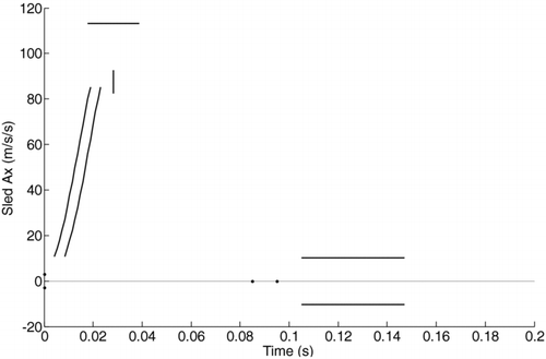
All tests were performed using the draft GTR-7 Phase 2 Annex 9 pulse requirements (UN Citation2010) shown in . The lines and dots form boundaries within which the sled acceleration must lie. The velocity change (delta V), and mean acceleration of the sled acceleration pulse are also stipulated in Annex 9.
Test Dummies and Instrumentation
For the main test program, 4 dummies from 3 laboratories were used (serial nos. 028, 068, 077, and 100). All 4 were prepared by Humanetics (Heidelberg Germany) according to the October 2011 TEG build, maintenance, and certification requirements, including pre- and posttest certification:
| • | TEG jacket test | ||||
| • | TEG without head restraint test | ||||
| • | TEG with head restraint test | ||||
Some additional tests were performed with dummies 006 and 007, which had previously been shown to have inadequate reproducibility (Bortenschlager et al. 2009).
Each dummy was fitted with the following instrumentation:
| • | Head triaxial acceleration (Ax , Ay , and Az ) | ||||
| • | Upper neck forces and moments (Fx , Fz , and My ) | ||||
| • | C4 biaxial acceleration (Ax and Az ) | ||||
| • | Lower neck (or T1) forces and moments (Fx , Fz , and My ) | ||||
| • | T1 left, T1 right, and T8 acceleration (Ax ) | ||||
| • | L1 biaxial acceleration (Ax and Az ) | ||||
| • | Pelvis triaxial acceleration (Ax , Ay , and Az ) | ||||
All instrumentation was fully calibrated, with CFCs (channel filter class) and CACs (channel amplitude class) to European New Car Assessment Programme (EuroNCAP) whiplash protocol (v3.1 June 2011), and data recording to SAE J211-1:2003.
Seating Procedure
The BioRID target backset was determined using a 3D H-point machine and head restraint measurement device, both calibrated to the EuroNCAP “Gloria” specification. The EuroNCAP v3.1 procedure was used, with one modification: The T-bar shall be held during steps 5.3.11 to 5.3.18 (EuroNCAP defines 5.3.11 to 5.3.17). This change was in line with Annex 12 of the draft GTR (UNECE 2011).
The BioRID dummy was installed according to the procedure defined in the EuroNCAP whiplash test protocol v3.1. Multiple locations on the dummy and seat were measured using a coordinate measuring machine before every test.
Table 1 Test matrix
Film Analysis
Film analysis was undertaken using a wide off-board camera view (per EuroNCAP protocol v3.1) additionally calibrated for lens distortion and camera position and orientation. The quality of calibration was assessed using ISO (International Organization for Standardization) 8721:2010 (www.iso.org).
Test Matrices
Initially 5 tests with each of 4 dummies (total 20 tests; Phase 1; see were run with a far head restraint position (75-mm backset). The order of testing with each dummy was randomized as far as was possible within the availability of each dummy and was in the order shown in .
It was planned to do 2 further batches of tests with near and mid head restraint positions. However, the results of the first 20 tests indicated significant reproducibility problems for several neck moment and force channels, so the remainder of the testing effort was redirected from repeatability and reproducibility to investigating the cause of the observed differences between the dummies and to suggest ways in which the reproducibility of the dummy responses could be improved. The final test matrix is shown in .
Results
Key
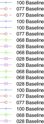
In the all of the graphs plotted in this article, the following key is used for the line styles (see also ):
Table 2 Key to the line styles used in the graphs
The following color code is used for each dummy:
Table 3 Key to the line colors used in the graphs
The following sign convention is used for all measurements (SAE J211-1:2007):
Table 4 Sign convention for all BioRID II dummy measurements
Test Condition and Dummy Positioning
Test Pulse
shows the sled pulse for the first 20 tests. The pulse is compliant with the draft GTR-7 pulse except for a slight excursion outside the corridor at 120 ms. This corresponds with the engagement of the dampers in the seat back, which occurred after all of the peak dummy responses. It was therefore considered that this would not influence the conclusions of the test program.
Fig. 4 Bundesanstalt für Straßenwesen (Bergisch Gladbach, Germany) sled pulse (20 tests) in the baseline tests (color figure available online).
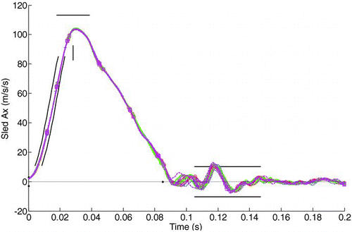
The sled pulse had a CV of 0.4 percent for the peak sled acceleration.
Seat Response
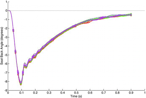
The displacement of the seat back was measured using linear variable differential transformers, from which the dynamic seat back angle was calculated (). The seat back recline angle was just over 8° and was very repeatable, with a CV of 1.4 percent. Some dummy-dependency can be observed in the seat back response; for instance, it can be observed that dummy 077 consistently rotated the seat slightly further rearward than dummy 028.
Dummy Positioning
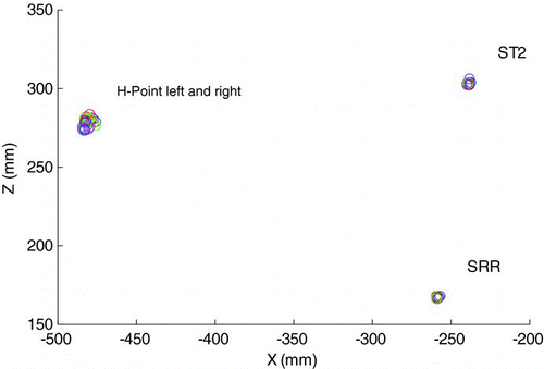
The coordinates of various BioRID and seat features were digitized before each test using a coordinate measuring machine. shows that the coordinates for the left and right H-points were ±5 mm across all 20 baseline tests. In general, the H-point heights were similar, except for dummy 028, where the H-point tended to be approximately 4 mm lower. It should be noted that the H-point tool was quite loose in some of the dummies tested and it was easily possible to move the tool more than ±5 mm. Therefore, within the accuracy of the H-point tool, it is not possible to comment for certain whether dummy 028 was lower in the seat.
Summary
The pulse, seat response, and dummy positioning indicate a very repeatable test setup and test condition. The main exception was a slight head restraint deformation of 0.6 mm in each test.
Dummy Responses in Baseline Tests
Instrumentation
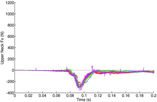
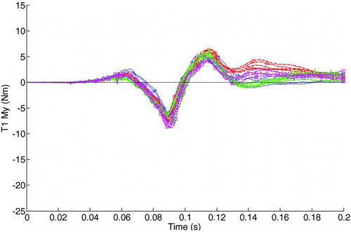
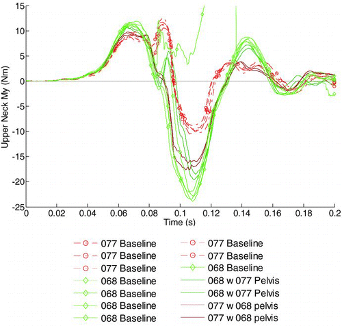
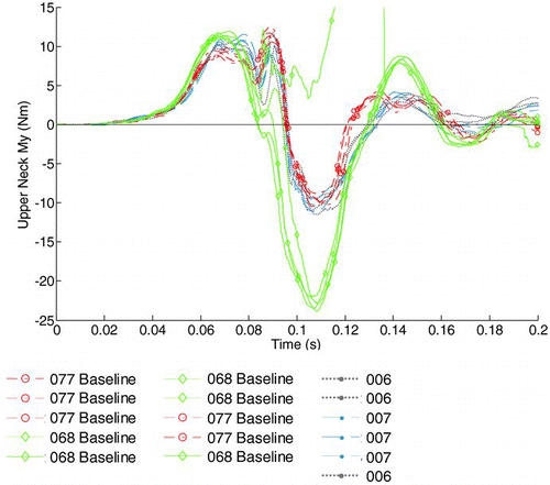
In the baseline tests, the upper torso and head accelerations, as well as some neck forces and moments, had acceptable repeatability and reproducibility (using the CV, calculated as the standard deviation of the peak value divided by the mean of the peak value, expressed as a percentage); for example, T1 Fx (CV 9.6%) and upper neck Fx (; CV 10.0%). However, 4 channels had poor reproducibility, in particular, T1 My (), with a CV of 14.4 percent, upper neck Fz (CV 18.6%), T1 Fz (CV 23.0%), and upper neck extension My (), with a CV of 30.3 percent (8.4% for flexion moment). Given the pseudorandom order of the tests and the clear grouping of the results for each dummy in , the poor reproducibility was attributed to differences between dummies and not test factors such as possible degradation of the seat foams. In , 2 tests have clearly different results:
Fig. 9 Upper neck moment about the Y-axis in the baseline tests (n.b.: the green curve that runs off the top of the graph was due to a loose connector; CV 30.3%) (color figure available online).
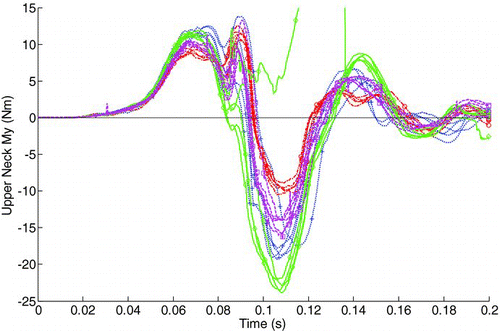
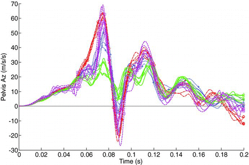
As noted in the Methods section, the focus of the program was therefore shifted to identifying the cause of these differences between dummies. Assessment of the dummy responses in the baseline tests showed that the pelvis acceleration was markedly different between dummies (Figure 12). It was also observed that the stiffness of the pelvis flesh on the 4 dummies varied considerably, from nearly new and soft to the touch to old, shrunken, and very hard to the touch. Softer pelvis flesh correlated with lower pelvis accelerations in Figure 12. This led to the hypothesis that pelvis flesh stiffness may be correlated with variations in dummy response at the other end of the spine.
Kinematics
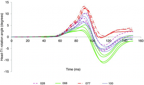
Film analysis showed dummy-to-dummy variability in pelvis angle (assessed using markers on the pelvis wand). Similar variability was observed at the T1 and head. Head rotation angle relative to T1 was clearly dummy-dependent, as shown in , with the reproducibility poor compared with the repeatability. Dummy 077 showed neck flexion throughout the rear impact event; dummy 068, however, showed an initial flexion response, with a maximum at the time of peak head restraint contact, followed by an extension response, with a peak at the time of peak upper neck My extension moment.
Fig. 15 OC displacement relative to T1 in a seat-back coordinate system (color figure available online).
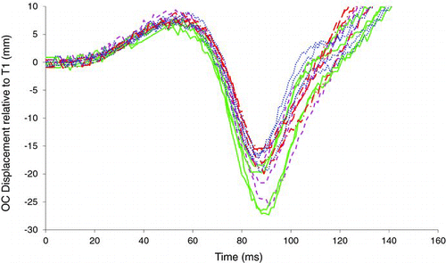
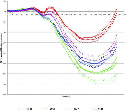
The ramping-up behavior of the dummies was also markedly different, with dummy 077 ramping up by less than 10 mm (in the global Z-axis, at the time of peak neck extension moment) and dummy 068 ramping up by approximately 30 mm (Figure 14). Variation in ramping-up response would be expected to affect spine interaction with the seat and head interaction with the head restraint and therefore would be likely to affect the measured neck loads. However, OC pin displacement relative to the T1 pin in a seat back coordinate system was found to be relatively insensitive to differences in ramping-up behavior (Figure 15). This measurement is similar to one previously proposed as a metric to use with BioRID II to control head restraint geometry in a dynamic seat test (Hynd and Carroll Citation2008).
Investigation of Sources of Variation in Dummy Responses
Modified Backset or H-Point
Several tests were run with dummy 068 in which the backset was moved either 20 mm forward or rearward compared with the baseline tests or the H-point height was raised 30 mm by placing foam on the seat base prior to installing the dummy (Phase 2, shown in .
Changes in backset were important for T1 and upper neck Fz measurements, but the repeatability of these responses in the baseline tests indicated that these parameters were adequately controlled within the BioRID seating procedure for a given target backset. The results also indicated that significant changes in backset had very little effect on the upper neck My extension moment.
Tests with the H-point raised by approximately 30 mm demonstrated the effect of pelvis interaction with the reinforced recliner bar, because the X-axis pelvis acceleration was markedly reduced with the higher H-point position. This suggested that the reinforcement will exaggerate any differences between dummies caused by this interaction compared with the OEM seat. However, it was felt that the reinforcement was necessary to achieve a repeatable test and any exaggeration of dummy differences would help to identify the cause of the differences.
Tests with 068 and 077 with Spines or Pelvises Swapped
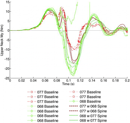
Several tests were conducted with dummies 068 and 077 (the outlying dummies in the baseline tests) with the spines or pelvises swapped between the dummies. Generally, swapping the pelvises was more influential than swapping spines. This may initially seem surprising, but the spine response is controlled in the certification tests, whereas pelvis stiffness is not controlled. Swapping either spines or pelvises had a similar large effect on upper neck My (Figures 10 and 16). Therefore, improved control on the response of both parts was recommended. It should be noted that only the jacket of dummy 068 met the draft jacket stiffness certification requirement and the variation in jacket stiffness may also have influenced the repeatability and reproducibility of the dummies. Therefore, it was recommended that all jackets should have a similar stiffness.
The performance of dummies 068 and 077 returned close to their original performance in the baseline tests when they were rebuilt to their original configuration.
Baseline Tests with 006 and 007
Dummies 006 and 007 had previously been shown to have poor reproducibility in a hard rally seat (Bortenschlager et al. 2009), particularly for upper neck My . Just prior to their use in the present test program, both dummies were refurbished by Humanetics with the following modifications:
| • | All cervical, thoracic, and lumbar bumpers were replaced with bumpers from the same batch (6 different specifications of bumper in total). | ||||
| • | All vertebrae were checked and replaced if the holes for the spine pins did not meet the tolerance defined by the Informal Group for the GTR BioRID specification. | ||||
| • | All spine pins were replaced with the stainless steel pins defined by the Informal Group for the GTR BioRID specification. | ||||
Figure 11 shows the response of both dummies (3 repeat tests for each) compared to the 20 baseline tests. The refurbishment process appears to have greatly reduced the differences between dummies 006 and 007 compared to previous test programs (the CV for upper neck extension moment My was 8.2%). The seat type and pulse have also been changed, so it is not possible to be certain about the extent of the change. However, both dummies also had much more consistent upper neck My and total head rotation responses in certification tests with head restraint after refurbishment.
Tests with 068 and 077 with Spine Refurbishment
During testing it was noticed that dummy 077 had narrower bumpers at the upper 2 rear thoracic spine positions (T2 and T3). These were used to tune the Pot C response in the certification test with head restraint. One test was run with these 2 bumpers replaced by standard thickness bumpers, and the dummy was also recertified with the standard thickness bumpers.
Fig. 17 Upper neck moment about the Y-axis for dummy 077 with standard thickness T2 and T3 rear bumpers compared to baseline tests with dummies 068 and 077 (color figure available online).
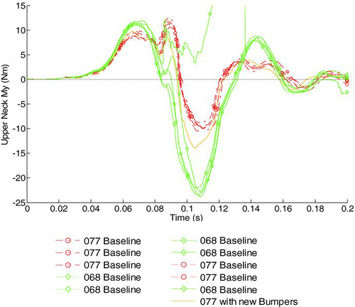
Fig. 18 Upper neck moment about the Y-axis (detail) for dummies 068 and 077 following spine refurbishment (color figure available online).
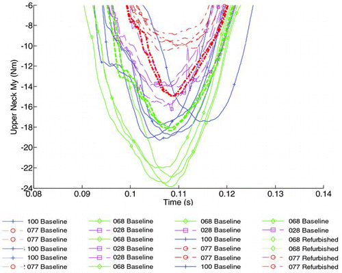
The replacement of just 2 bumpers in the upper rear thoracic spine of dummy 077 had a pronounced effect on a number of channels, particularly those with poor reproducibility in the baseline sled tests (see, for example, ). This change was also picked up in certification, and the dummy failed the Pot C certification requirement with the replacement bumpers. However, dummy 077 had a response close to the top edge of the Pot C corridor; a similar change in the stiffness of these 2 bumpers on dummy 068 (which was closer to the bottom edge of the Pot C corridor) would not have caused the dummy to fail but would be expected to cause an equivalent change in seat test responses.
The spines of dummies 068 and 077 were then refurbished, including the following:
| • | All cervical, thoracic, and lumbar bumpers were replaced with bumpers from the same batch (6 different specifications of bumper in total). | ||||
| • | All vertebrae were checked and replaced if the holes for the spine pins did not meet the tolerance defined by the Informal Group for the GTR BioRID. | ||||
| • | All spine pins were also checked and found to comply with the GTR-7 Informal Group specification, so none were replaced. | ||||
T1 and upper neck Fz were markedly affected for both dummies, with an increase in the magnitude of both and a delay in the response of both. The refurbishment of these 2 dummies also caused their upper neck My responses to converge considerably compared to the baseline tests ().
Bumper Stiffness
The properties of the bumpers fitted to dummies 028, 068, 077, and 100 as used in the baseline tests is not known. However, when refurbishing dummies 006 and 007, and later dummies 068 and 077, quasistatic compression tests were performed on each batch of bumpers for each of the 6 standard bumper types used in the BioRID II dummy. The coefficient of variation for the applied compressions and the mean force is shown in .
Discussion
The original objective of the work was to evaluate the repeatability and reproducibility of the BioRID IIg dummy in loading conditions that were as close as possible to the loading conditions that the dummy will experience in seat testing. This was achieved by using a production seat base and seat back as the interface between the dummy and a spring–damper mechanism that controlled the seat back response. In practice, these repeatability and reproducibility tests therefore include dummy repeatability and reproducibility plus elements of test condition (e.g., sled pulse, spring–damper response, slight rearward permanent deformation of the head restraint of about 0.6 mm in every test) and test procedure (e.g., variability in dummy positioning) repeatability and reproducibility.
Table 5 Batch-to-batch variation of quasistatic compression test results for bumpers fitted to dummies 006/007 and 068/077
Though these factors may affect repeatability, they were clearly small compared to the dummy-to-dummy differences that caused the observed poor reproducibility for some channels in the baseline test series. Upper neck My , upper neck Fz , and T1 (lower neck) Fz showed particularly poor reproducibility. It should be noted that at the time of writing, the GTR-7 Informal Group has not yet selected injury or seat assessment criteria for use with the BioRID II dummy, so it is not known whether any of these channels would be used in the regulation.
Nevertheless, the focus of the work was shifted to investigating the causes of the observed variations. As a result, detailed assessment of the repeatability and reproducibility was not undertaken but would be required once dummy and certification procedures have been updated and the dummy retested. The reinforced recliner bar and head restraint were both more rigid than is typical for a production seat, and there was some evidence that this may exaggerate differences between dummies. However, tests with the refurbished dummies 006 and 007 showed very closely matched upper neck My response, which demonstrated that good reproducibility was possible despite the rigidity of the recliner bar and head restraint.
Swapping parts between the outlying dummies 068 and 077 showed that the pelvis and spine were both very influential in the dummy responses. Indeed, the pelvis was more influential in these tests, although that may be related to the stiffness of the recliner bar in these tests. It should be noted that some seats do have stiff structures at this level, so it is important that the consistency of pelvis response is improved. The jackets were also swapped in the spine swap tests and it is possible that jacket stiffness could also be influential.
The tests in which backset was varied indicated that a consistent BioRID posture and target backset would be very important, particularly for T1 and upper neck Fz measurements. The responses in the baseline tests suggest that the BioRID seating procedure gives sufficient control of the BioRID posture. However, the repeatability and reproducibility of the target backset measurement made with the 3D H-point machine and head restraint measurement device have not been assessed in this test program.
The sensitivity of dummy 077 to changes in just 2 bumpers in the upper thoracic spine demonstrated that tight control of bumper stiffness is likely to be important for improving reproducibility. It also exposed a potential problem with the process used to tune the dummy response in certification tests. Currently, the top 2 rear thoracic bumpers may be substantially changed (different thickness and stiffness) in order to tune the response in the certification test. However, if one of the outcomes of the certification test is to tune just the top few rear thoracic bumpers, this may simply be compensating for a difference in stiffness lower down the spine.
This may be the reason that replacement T2 and T3 rear bumpers in dummy 077 gave an upper neck My and T1 and upper neck Fz response closer to the other baseline dummies, even though this modification meant that the dummy failed the certification test (the bumpers installed for the baseline tests were thinner in order to pass the certification requirements). This suggests that the certification test may result in a standardized T1 response in the specific loading scenario of the certification test but may not standardize—or may even increase the range of—T1 response in seat tests. It seems that the response of the spine at each level needs to be controlled in order to ensure reproducible measurements. A quasistatic spine stiffness test was developed as a first attempt at controlling the localized spine stiffness for the whole spine. However, this was not found to be effective and it may be that batch testing of the quasistatic stiffness of individual bumpers is required.
It was also observed that the primary neck response in these tests was flexion, not extension. This correlates well with recent findings reported to the GTR-7 Informal Group by Japan and the United States, which found a correlation between neck flexion and injury in accident replication simulations and PMHS studies, respectively.
Recommendations
Based on the results of this test program, the following modifications to the BioRID IIg dummy and its certification procedures were recommended:
| • | All dummies should have jackets that meet the jacket certification requirement. The current draft requirement may be updated following a review underway by Humanetics at the time of writing. | ||||
| • | The pelvis certification tests to the base and rear of the pelvis should be re-introduced with tight requirements on the stiffness of the pelvis flesh. | ||||
| • | Tight control of bumper properties should be implemented. | ||||
| • | Certification requirements should be developed for the certification test with head restraint. Additional comparative certification and seat test data are needed in order to set these requirements. | ||||
| • | Consideration should be given to updating some of the requirements in the certification; for example, tightening the corridors on the Pot A, Pot B, total head rotation, and total thoracic rotation responses. | ||||
| • | The tolerance on input parameters for the certification sled tests should be tightened, because currently the input for the certification test can be as variable as the target dummy reproducibility. | ||||
| • | The primary neck bending response in this seat test series was flexion, not extension, which will be controlled by the front cervical bumpers. However, these bumpers are not as well controlled in the certification tests as the rear bumpers. A better way to check the performance of these bumpers is recommended. | ||||
Conclusions
A large program of sled tests has been conducted to investigate the sources of variation in the BioRID II dummy. The test condition was highly repeatable, with a very repeatable pulse, a well-controlled seat back response, and minimal observed degradation of seat foams across the test program. Very slight yielding of the head restraint was observed in each test, but this did not affect the repeatability of tests with a single dummy and so was not considered to be a significant factor in most tests. The head restraint was replaced twice during the test program, when the amount of yielding increased markedly. The sled and seat responses were considered sufficiently repeatable to be used to evaluate the reproducibility of the dummy in baseline tests and the effect of changes to the dummy build level.
Some reproducibility issues were identified, particularly for T1 and upper neck Fz and for T1 and upper neck My . It should be noted that the GTR-7 Informal Group has not yet selected injury or seat assessment criteria for use with the BioRID II dummy, so it is not known whether any of these channels would be used in the regulation. However, there was also poor reproducibility for the ramping-up behavior of the dummy, which would be expected to be fundamental to the reproducibility of dummy measurements in general.
As a result of these findings, the planned test matrix was revised to focus on an extensive program of tests to attempt to identify which dummy characteristics were responsible for the observed reproducibility issues and to identify whether updates may be required to the certification procedures in order to ensure dummy reproducibility. Both the pelvis and spine characteristics were found to significantly influence the dummy measurements for which poor reproducibility was observed.
Recommendations have been made for improvements to the dummies to improve reproducibility. This includes recommendations for additional certification tests and updates to the existing certification tests to control dummy performance better.
Since the work reported here, 4 BioRID II dummies (including 3 dummies from the baseline test series) have been updated in line with the recommendations made herein to give more consistent pelvis, jacket, and spine bumper performance. At the time of writing, these dummies are being evaluated in the same test condition to assess the effect of the updates on the repeatability and reproducibility of the dummies.
Acknowledgments
The authors acknowledge the contributions of the following: The European Commission, for funding the work; Michael Züge and Marc Jansen from BGS Böhme & Gehring GmbH, who performed all of the dummy testing on the HyGe sled at BASt; Tobias Langner from BASt; Alex Schmitt and Mike Beebe from Humanetics; and all those who provided BioRID dummies for the test program.
References
- Bortenschlager , K , Hartlieb , M , Hirth , A , Kramberger , D and Stahlschmidt , S. Detailed analysis of BioRID-II response variations in hardware and simulation. Paper presented at: 21st International Technical Conference on the Enhanced Safety of Vehicles; June 15–18 . Stuttgart , , Germany
- Carroll , J , Willis , C and Hynd , D . 2007 . Assessment of Rear Impact Dummy Biofidelity EEVC WG12 Report 505B. Available at: www.eevc.org
- Hynd , D and Carroll , J . 2008 . Evaluation of Concepts for Dynamic Test Procedures for the Control of Head Restraint Geometry , Crowthorne , , UK : Transport Research Laboratory . Project Report PPR 471
- Hynd , D , Svensson , M , Trosseille , X , van Ratingen , M and Davidsson , J . 2007 . Dummy Requirements and Injury Criteria for a Low-Speed Rear Impact Whiplash Dummy EEVC WG12 Report Document Number 505A. Available at: www.eevc.org
- Kang , Y-S , Bolte , J IV , Moorhouse , K , Donnelly , B , Herriott , R and Mallory , A . 2012 . Biomechanical responses of PMHS in moderate-speed rear impacts and development of response targets for evaluating the internal and external biofidelity of ATDs . Stapp Car Crash J. , 56 : 105 – 170 .
- Moorhouse , K , Donnelly , B , Kang , Y-S , Bolte , J IV and Herriott , R . 2012 . Evaluation of the internal and external biofidelity of current rear impact ATDs to response targets developed from moderate-speed rear impacts of PMHS . Stapp Car Crash J. , 56 : 171 – 229 .
- Rhule , D , Rhule , H and Donnelly , B . The process of evaluation and documentation of crash test dummies for Part 572 of the Code of Federal Regulations . Paper presented at: 19th International Technical Conference on the Enhanced Safety of Vehicles; June 6–9 , Washington, DC
- United Nations . 2008 . Global Registry. Addendum: Global Technical Regulation No. 7—Head Restraints. , Geneva , , Switzerland : United Nations .
- United Nations Economics Commission of Europe (UNECE) . 2010 . Draft GTR-7 Phase 2 Document GTR7–06–10e Rev 1 Available at: http://www.unece.org/trans/main/wp29/wp29wgs/wp29grsp/gtr7phase2_6.html. Accessed February 28, 2010
- United Nations Economic Commission for Europe (UNECE) . 2011 . (Japan) Review of Regulatory Text (Rev. 1) Document GTR 7-06-10 Rev.1 Available at: http://www.unece.org/trans/main/wp29/wp29wgs/wp29grsp/gtr7phase2_6.html. Accessed February 2011
![Fig. 1 Structure of the seat rig, showing the seat back reinforcement and spring–damper system (OEM [original equipment manufacturer] seat cushion and seat back not shown) (color figure available online).](/cms/asset/50c5bc0f-2365-42ff-b36e-2676b72ff1ee/gcpi_a_806987_o_f0001g.jpg)
