Abstract
Objective: The purpose of this study was to investigate the effects of abuse conditions, including realistic crash scenarios, on Li ion battery systems in E-vehicles in order to develop safe practices and priorities when responding to accidents involving E-vehicles.
Method: External fire tests using a single burning item equipment were performed on commercial Li ion battery cells and battery packs for electric vehicle (E-vehicle) application. The 2 most common battery cell technologies were tested: Lithium iron phosphate (LFP) and mixed transition metal oxide (lithium nickel manganese cobalt oxide, NMC) cathodes against graphite anodes, respectively. The cell types investigated were “pouch” cells, with similar physical dimensions, but the NMC cells have double the electric capacity of the LFP cells due to the higher energy density of the NMC chemistry, 7 and 14 Ah, respectively.
Heat release rate (HRR) data and concentrations of toxic gases were acquired by oxygen consumption calorimetry and Fourier transform infrared spectroscopy (FTIR), respectively.
Results: The test results indicate that the state of charge (SOC) affects the HRR as well as the amount of toxic hydrogen fluoride (HF) gas formed during combustion. A larger number of cells increases the amount of HF formed per cell. There are significant differences in response to the fire exposure between the NMC and LFP cells in this study. The LFP cells generate a lot more HF per cell, but the overall reactivity of the NMC cells is higher. However, the total energy released by both batteries during combustion was independent of SOC, which indicates that the electric energy content of the test object contributes to the activation energy of the thermal and heat release process, whereas the chemical energy stored in the materials is the main source of thermal energy in the batteries.
Conclusions: The results imply that it is difficult to draw conclusions about higher order system behavior with respect to HF emissions based on data from tests on single cells or small assemblies of cells. This applies to energy release rates as well. The present data show that mass and shielding effects between cells in multicell assemblies affect the propagation of a thermal event.
Introduction
Li ion batteries contain high electric energy and possess high power density and contain combustible materials and fluorine-based salts (Wilken et al. Citation2012, 2013; Yang et al. Citation2006). Risk analysis identifies thermal abuse as a key pathway to critical failure of Li ion batteries (Sturk and Hoffmann Citation2014) as illustrated in Fig. A1 (see online supplement). A critical failure event is here defined as an incident involving emission of combustible gases and the subsequent risk for ignition of these gases leading to fire. The main cause for ventilation of gases from an Li ion cell is the exothermal breakdown of its internal components, mainly the electrolyte, initiated by an increase in the internal temperature of the cell.
Gases emitted during a thermal event in Li ion batteries contain a variety of organic and inorganic species, including flammable constituents like hydrogen and hydrocarbons (e.g., methane and ethane) as well as vaporized electrolyte (alkyl carbonate; Magna Steyr Fahrzeugtechnik AG & Co. KG 2009). The emitted gases may also contain varying concentrations of highly toxic CO and hydrogen fluoride (HF). The organic solvents in the Li ion battery electrolyte and the conductive salt LiPF6 are the major source of the gaseous species. Yang et al. (Citation2006) studied thermal stability of Li ion battery electrolytes containing LiPF6 salt. These investigations show that the rate of gas evolution increases at about 170°C and that the generation of HF is limited below this temperature. A conventional internal combustion engine (ICE) vehicle fire also generates toxic gases, including HF released during combustion of polymer materials in the vehicle structure. Lecocq et al. (Citation2012) have compared relative amounts of HF generated by conventional ICE cars and E-vehicles (i.e., any type of vehicle with electric propulsion) to evaluate the contribution made by the traction battery. Their test involved combustion of 4 vehicles: 2 ICE and 2 E-vehicles, all manufactured by French automotive manufacturers. The vehicles were fully fueled/charged. Their results show that an increase in HF generation can be seen in the E-vehicles after 25–30 min when the traction battery has started to burn and that the total amount of HF released from an E-vehicle is approximately double the amount released from an ICE vehicle, on the order of 1,500 g HF for the E-vehicles compared to 600–800 g HF for the ICE vehicles. Because gaseous HF is a U.S. Department of Transportation Hazard Class 8 substance and is toxic at parts per million levels, there is reason for concern among first responders. The U.S. National Institute for Occupational Safety and Health defines upper limit exposure concentration as an average of 3 ppm (2.6 mg/m3) during 15 min. However, HF is readily dissolved in water and fire-fighting measures using water will greatly reduce the concentration of toxic gas in the vicinity of the vehicle, thus mitigating the potential toxicity of Li ion battery fires.
A Swedish research project named E-Vehicle Safe Rescue was performed during 2012–2014 by the Swedish Civil Contingencies Agency together with industry and academic partners. The purpose was to investigate the effects of abuse conditions, including realistic crash scenarios, on Li ion battery systems in E-vehicles in order to develop safe practices and priorities when responding to accidents involving E-vehicles. The present work uses results generated within the E-Vehicle Safe Rescue project for in-depth analysis of parameters affecting the battery when exposed to external fire.
Experimental Setup
Fire tests have been conducted on Li ion cells designed for E-vehicles. Abuse testing is commonly performed on single cells or smaller cell assemblies in order to simplify test procedures, manage risks, and reduce the costs for testing. The tested cells represent the 2 Li ion cell technologies that currently predominate on the market for E-vehicles: lithium iron phosphate (LFP) and mixed transition metal oxide (NMC). Two types of pouch cells of similar geometry and size were studied; however, the electric capacity differs between the cells due to the differences in energy density of the cathode materials: 7 Ah LFP (LiFePO4) and 14 Ah NMC (Li(Ni1/3Mn1/3Co1/3)O2). Six series of tests were performed as described in Table A1 (see online supplement). For the multicell configurations (i.e., series A, B, D, E), the cells were physically but not electrically connected and the cell bundles were held together with metal wire. In series C and F, the cells were assembled in pack and module configurations, respectively; hence, the cells were already electrically connected and mounted in frames. One complete commercial E-vehicle battery pack using NMC cell technology (series C) was tested.
The test samples were precycled and prepared to the state of charge (SOC) levels 25, 50, 75, and 100%, as shown in Table A1. The SOC levels are based on the capacity rating of the test samples. Tests were also conducted on samples that had been completely drained of electric energy by discharging over a resistive load and then externally short circuited (0 V) for 5 days. The purpose of the latter tests was to determine the chemical energy content of the cells and the reactivity of the batteries toward external heating when no activation in the form of electric energy was present. The NMC battery pack was tested at 80% SOC.
Figure A2 (see online supplement) shows the experimental set ups for the fire tests on cells, cell bundles, and battery packs. In the bonfire tests on cells, a single burning item (EN 13823) equipment was used, as shown in Fig. A2a. The pouch cells were generally placed lying horizontally on a metal net with the burning flame on the flat side facing down. In the multicell bundles, the rest of the cells were stacked on top of the first cell. Complementary tests were performed on an additional bundle of 5 cells being oriented so that the cells were standing vertically beside each other. The purpose of this test was to investigate whether the orientation of the cells with regard to the heat source affected the test results. The test of the complete NMC battery pack was performed on a larger burner so that even heating of the test object was achieved (see Fig. A2b).
In all of the measurement series, the heat release rate (HRR) and heat energy generated from the cells and pack were quantified by oxygen consumption calorimetry. The emitted gases were identified and the specific concentrations of CO2, CO, HF, and POF3 were quantified by means of Fourier transform infrared spectroscopy (FTIR) according to the methodology for time-resolved measurements in ISO 19702 (2006). The sampled smoke gases were filtered before entering the FTIR gas cell. The filter was analyzed for fluorine after each test to quantify any losses of fluorine containing products in the filter. The total production of HF was additionally quantified by sampling using gas-solution absorbers. Two gas-washing bottles connected in series filled with a carbonate buffer were used for accumulative sampling of the smoke gases. The absorption solutions were subsequently analyzed for fluorine using high-performance liquid chromatography. The weight loss of cells was studied in order to provide a basis for analysis and comparison to the gases emitted.
Results
Thermal Energy Release
shows the total energy released for LFP and NMC cells, respectively, as a function of SOC. The energy release is normalized per cell and per Ah in order to enable comparison between the 2 cell chemistries. Test data show that there is no significant difference in the total energy released as a function of SOC of the tested cell. Additionally, there is very little difference in the total energy release from the 2 cell types, despite the large difference in electric energy density. Consequently, the energy release in kJ/Ah is half for the NMC cells compared to the LFP cells.
Table 1. Heat energy released during complete burnout of LFP and NMC cells in bonfire tests
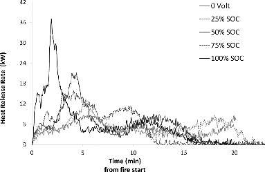
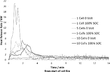
and show the HRR for LFP cells. In , fire tests on bundles of 5 cells at different SOC, ranging from 25 to 100%, are plotted. The test data show that, although the high SOC seems to promote a faster HRR, the activating role of the SOC rapidly drops, and there appears to be no significant difference in the driving force for heat release between 50 and 75% SOC. depicts the HRR per cell as a function of the number of cells (1, 5, and 10) in the tested object for 0 and 100% SOC. There is an inverse relationship between the number of cells and the peak HRR released per cell. Table A2 (see online supplement) shows peak HRR data at 0 V and 100% SOC for single cells and 5- and 10-cell assemblies, respectively.
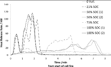
The corresponding HRR data for bundles of 5 NMC cells as a function of SOC are shown in . The dependence on SOC for the onset of heat release is even more marked for the NMC cells than for the LFP cells. The cells tested at 100 and 75% SOC show a very rapid HRR onset that quickly decreases as the cells are consumed, whereas the 50 and 25% SOC samples act similar to each other and have a notably slower HRR onset and a prolonged period of heat evolution. The higher reactivity of the NMC cells manifests itself in significantly higher HRR rates than for LFP. The test data for duplicate NMC samples show good correlation, which supports that the observed SOC dependence is significant.
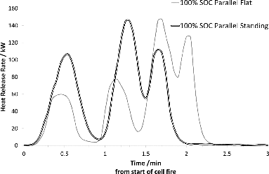
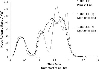
In order to enable transfer of charge between the cells during the thermal event, the effect of electric connection between cells and the dependence on how the test objects are oriented with respect to the heat source was also investigated for the NMC cells. shows that orientation of the samples influences the HRR process. The HRR process is faster and there are fewer peaks (peaks represent bursting of new cell(s)) for assemblies placed vertically with respect to the heat source than for those placed lying horizontally over the burner. shows that there is no difference in HRR behavior for cells that are electrically connected compared to cells that are not.
Burning the complete NMC battery pack generated 0.5 MW in addition to the 1.5 MW supplied by the burner. There were no fluoro-containing components in the emitted fumes detectable by FTIR, nor were there any traces of HF found in the ventilation filters after the test. Fire extinguishing was performed in 2 steps. The flames were quenched by spraying large amounts of water for 2 min on the outside surface and then the battery was observed for 18 min with no reigniting occurring. The battery was then flushed thoroughly with water for 7 min. The battery continued to generate fumes and the internal temperature stayed at about 300–350°C for hours following the fire quenching procedure. After 6 h the thermocouples inside the battery showed 80°C.
HF Emission
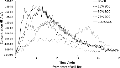
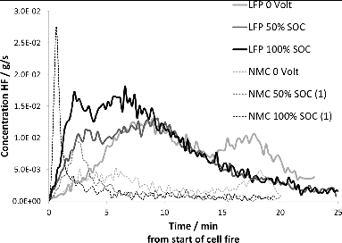
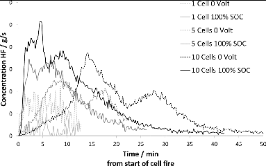
and show the release rate of HF as a function of time for LFP and NMC cell bundles, respectively. In both and , there is an SOC dependence in the HF release, so that the cell bundles in the mid-SOC range have higher HF peaks, although the total amount released is less than for the bundles with higher SOC. However, the differences are small and more tests are required to verify the dependence of HF on SOC. Duplicate tests have been performed on NMC cells, showing good consistency between samples. indicates that HF emissions from NMC cells are significantly lower than those for LFP cells. shows that the number of cells affect the amount of HF released on an average from each cell. Cell assemblies with a larger number of cells appear to generate more HF per cell than single cells or assemblies with fewer cells.
Discussion
Several of the tests in this study are performed on single cells or cell assemblies including multiple cells that are connected physically but not electrically. During planning of the tests it was assumed that electrical connection would not influence the test results significantly because the conductivity is lost once the cell seal has ruptured due to overpressure and venting, and the cell circuit is completely disabled. It was therefore assumed that electric connection between cells was not necessary. This assumption was verified later by burning tests on NMC cell assemblies including 5 and 10 cells that were connected in parallel within each assembly and consequently our data indicate that this is a valid assumption.
shows a comparison of HRR between the 7 Ah LFP and the 14 Ah NMC cells. The total amount of electric energy stored in the cells did not significantly affect the total amount of heat energy released. This indicates that the chemical energy per unit weight of Li ion cells is much higher than the electric energy. The NMC cells have a significantly faster HRR than the LFP cells in these tests. For LFP cells it is apparent that medium (i.e., 50%) and high (75 and 100%) SOC lead to a higher HRR than lower (0 and 25%) SOC, but the relationship does not appear to be linear. The NMC cells showed a similar trend, although the peak HRR of the NMC cells was much higher than for the LFP cells, indicating a higher reactivity in the NMC cells. The dependence on SOC implies that the electric energy content contributes to the onset of the thermal event by providing activation energy needed to initiate thermal runaway or combustion of electrolyte. This is most evident at high SOC, and the importance of the electric energy as a driver for the thermal event appears to be less at medium to low SOC. For LFP cells the current data may be interpreted as the dependence of SOC is less marked below 75% SOC.
However, the difference between the total energy released per cell is small, with regards to both cell type and SOC. Consequently, the energy released per Ah is almost double for the LFP cells compared to the NMC cells. This may be explained by the 2 cell types having almost the same volumes despite the large difference in capacity. A possible conclusion is that the LFP cells and the NMC cells contain similar amounts of electrolyte, which is the main contributor of heat energy released during combustion. It is common to refer to the cathode material when discussing parameters of safety and thermal runaway (Roth Citation2008). However, the cathode material may not be the weakest link in all cell types. Instead, focus is currently set on the composition of electrolytes (Wilken et al. Citation2012, 2013). The organic electrolyte is claimed to contain more combustible energy per unit mass than the Li ion battery cell offers in electric energy (Huang et al. Citation2008; Wang et al. Citation2006). The manufacturers’ use of flame retardants and additives further adds to the diversity in results when it comes to fire propagation, heat evolution, and amounts of toxic species generated under thermal abusive conditions (Xiao et al. Citation2006). Our test results, and especially the similarity between the total energy released by the LFP and NMC cells, respectively, as shown in Table 1, support the importance of the electrolyte contributing to the fire and the amount of combustion energy formed. The tested NMC cells have twice the electric capacity of the tested LFP cells. Additionally, LFP is generally portrayed as a “safe” cathode material. Nonetheless, despite the somewhat slower propagation of the fire in the LFP cells, the combustion energy released in the event of the Li ion battery catching fire appears to be more closely related to cell volume, and hence content of chemical constituents, rather than specific electric energy density of the cathode material.
This investigation shows that the amount of toxic emissions per LFP cell increases with the number of burning cells (Table A3, see online supplement). A possible explanation is that the highly reactive HF and its intermediary PF5 are able to accumulate before being vented from the cells not directly exposed to the flame while the bottom cell acts as a thermal shield. According to Yang et al. (Citation2006), accumulation of intermediary PF5 inside the upper cells prior to venting made possible by the shielding effect of the cell closest to the flame results in higher HF concentrations as the PF5 reacts with humidity in the air after ventilation. This is consistent with the observed increase in measured HF emission with the number of cells in the test assembly seen in this investigation. A higher SOC also results in more HF released per cell, indicating that the higher SOC increases the overall reactivity inside the cells. However, the presently available sample size is too small to derive a quantitative relationship between SOC and HF generation. There is a significant difference in the behavior, and particularly the rate of HF released from the LFP cells compared to the NMC cells, as seen in Table A4 (see online supplement) and in Fig. 7, especially at high SOC. LFP cells appear to release more HF than NMC cells in total but over a longer time period. This is consistent with the observation of the shielding effect on HF generation; that is, when the onset of HF gas emission is very fast, there is less time to form intermediary PF5 inside the cell before venting and consequently the total HF amount emitted is less than when venting occurs later on in the thermal process. This can be seen in Fig. 8, where it is apparent that the 10-cell battery assemblies generated more HF per cell than the 5-cell assemblies and the single cells. This implies that it is difficult to draw conclusions about higher order system behavior with respect to HF emissions based on data from tests on single cells or small assemblies of cells. This applies to energy release rates as well; the present data show that mass and shielding effects between cells in multicell assemblies affect the propagation of a thermal event.
Another plausible explanation for the reduced total amount of HF in burning tests is that the composition of the gaseous species formed during electrolyte decomposition may be affected by the cathode material in the cell or the level of electrification of the electrode surface. According to Hammami et al. (Citation2003), the nickel and manganese in NMC cathode materials may catalyze that formation of organic fluoro compounds, such as fluoroethanol ether. If the electrolyte decomposition reactions are catalyzed by the cathode electrode, it is possible that the specific degradation mechanisms of the electrolyte obtained in contact with the NMC surface differ from those obtained by LFP, potentially leading to the formation of other gaseous species not included in this study. The NMC cells tested generate significantly less total amount of HF gas than the LFP cells tested. However, only one cell type from a single supplier was tested for each chemistry, so it is impossible to conclude whether this is a general characteristic of NMC cells.
The possiblity of HF emissions in critical thermal events involving Li ion traction batteries in E-vehicles is causing a lof of concern and uncertainties among policy makers and first responders. However, it is important to remember that conventional ICE vehicles also give rise to toxic substances in the event of fire, including HF. Lecocq et al. (Citation2012) reported that the additive contribution of HF from the traction battery is about a factor 2 compared to equivalent ICE vehicles and the duration of potential HF evolution is longer for E-vehicles compared to ICE vehicles.
Acknowledgments
Our partners in the E-Vehicle Safe Rescue project—The Swedish Civil Contingencies Agency (MSB), Volvo Car Corporation, Presto, and Umeå University—are gratefully acknowledged for fruitful collaboration and valuable discussions during the course of the project. Fire testing was performed by SP Fire staff during 2013 and 2014.
Funding
The Swedish Governmental Agency for Innovation Systems (VINNOVA) is gratefully acknowledged for financial support to the E-Vehicle Safe Rescue project within the FFI framework.
Supplemental Materials
Supplemental data for this article can be accessed on the publisher's website
Appendix
Download Zip (4.7 MB)References
- Hammami A, Raymond N, Armand M. Lithium-ion batteries. Runaway risk of forming toxic compounds. Nature. 2003;42:635–636.
- Huang Q, Yan M, Jiang Z. Thermal study of organic electrolytes with fully charged cathodic materials of lithium-ion batteries. J Solid State Electrochem. 2008;12:671–678.
- Lecocq A, Bertana M, Truchot B, and Marlair G. Comparison of fire consequences of an electric vehicle and an internal combustion engine. Paper presented at: 2nd International Conference on Fire in Vehicles (FIVE); September 27–28, 2012; Chicago, IL.
- Magna Steyr Fahrzeugtechnik AG & Co KG. Safety Guideline for Energy Storage System 120 kW. Author; 2009.
- National Institute for Occupational Safety and Health. Available at: http://www.cdc.gov/niosh/idlh/7664393.html. Accessed November 11, 2014.
- Roth EP. Abuse response of 18650 Li-ion cells with different cathodes using EC:EMC/LiPF6 and EC:PC:DMC/LiPF6 electrolytes. ECS Trans. 2008;11:19–41.
- Sturk D, Hoffman L. Fundamental Analysis for Risk Assessment of E-vehicles Involved in Traffic Accidents. SP Technical Research Institute of Sweden; 2014.
- Toxicity Testing of Fire Effluents—Guidance for Analysis of Gases and Vapours in Fire Effluents Using FTIR Gas Analysis. ISO 19702:2006.
- Wang Q, Sun J, Yao X, Chen C. Micro calorimeter study on the thermal stability of lithium ion battery electrolytes. J Loss Prev Process Ind. 2006;19:561–569.
- Wilken S, Johansson P, Jacobsson P. Infrared spectroscopy of instantaneous decomposition products of LiPF6-based lithium battery electrolytes. Solid State Ionics. 2012;225:608–610.
- Wilken S, Treskow M, Scheers J. Initial stages of thermal decomposition of LiPF6-based lithium ion battery electrolytes by detailed Raman and NMR spectroscopy. RSC Advances. 2013;3:16359–16364.
- Xiao A, Li W, Lucht BL. Thermal reactions of graphite with LiPF6 based electrolytes. J Power Sources. 2006;162:1282–1288.
- Yang H, Zhuang GV, Ross PN Jr. Thermal stability of LiPF6 salt and Li-ion battery electrolytes containing LiPF6. J Power Sources. 2006;161:573–579.

