 ?Mathematical formulae have been encoded as MathML and are displayed in this HTML version using MathJax in order to improve their display. Uncheck the box to turn MathJax off. This feature requires Javascript. Click on a formula to zoom.
ABSTRACT
Objectives: In order to understand the mechanisms of traumatic brain injury (TBI) and develop proper safety measures, it is essential that accurate instrumentation methods are utilized. The brain injury criterion (BrIC) has been developed and validated to predict brain injuries in combination with the head injury criterion (Takhounts et al. 2011, 2013). Because the validated BrIC is heavily dependent on angular motion, the accuracy of any head instrumentation technique should be judged in part by its ability to measure angular motion. The main objective of this study was to evaluate a method of accurately measuring 6-degree-of-freedom (DOF) anthropomorphic test device (ATD) head kinematics using a coplanar 6 accelerometers and 3 angular rate sensors (6a3ω) configuration.
Methods: A coplanar 6a3ω configuration (c6a3ω) was implemented via a newly designed fixture. The c6a3ω fixture was placed at the center of gravity (CG) of a Hybrid III 50th percentile ATD (HIII 50) head. In addition, a tetrahedron fixture with 9 installed accelerometers (tNAAP) was externally mounted on the posterior surface of the HIII 50 skull cap. The c6a3ω setup also allowed for comparison to the 3a3ω configuration (i3a3ω) by subsequently treating the c6a3ω fixture as an i3a3ω fixture by only using accelerations and angular rates from select sensors. A total of 63 tests were conducted by impacting the head–neck apparatus at various high speeds and directions by a pneumatic ram. Normalized root mean square deviation (NRMSD), peak differences, and uncertainty were used for quantitative evaluation of the 3 configurations (e.g., c6a3ω, i3a3ω, and tNAAP).
Results: The average NRMSD and peak differences between the calculated angular accelerations were less than 5% between the tNAAP and the c6a3ω with 5.6% of uncertainty but greater than 18% for NRMSD and 20% for the peak differences between the tNAAP and i3a3ω with 58.2% uncertainty. Average NRMSD and peak differences between transformed resultant linear accelerations and gold standards (accelerations directly measured by accelerometers at the origin of tNAAP or c6a3ω fixtures) were also calculated. The c6a3ω had both NRMSD and peak differences less than 3% (uncertainty of 2.5%), and i3a3ω had NRMSD, peak values, and uncertainty on the order of 20% and higher. The tNAAP was slightly less accurate than the c6a3ω for transformed accelerations (NRMSD and peak differences <6%, uncertainty of 4.6%) and showed NRMSD and peak differences in the 7–8% range for angular velocity and rotation (uncertainty of 4.3 and 6.7%, respectively).
Conclusions: The c6a3ω configuration exhibited much better accuracy for calculating angular acceleration and transformed linear acceleration than the i3a3ω configuration. The tNAAP showed slightly less accurate transformed linear acceleration than the c6a3ω and was demonstrated to have less accuracy than c6a3ω and i3a3ω for calculating angular velocity and rotation. The c6a3ω configuration could be a potential alternative to specialized NAAP ATD heads because all kinematics can be measured near the head CG, and 6a3ω instrumentation provides the most comprehensive 6DOF kinematics (i.e., accelerations, velocities, and displacements) with accuracy.
Introduction
Every year, nearly 1.5 million American citizens suffer a traumatic brain injury (TBI) due to events ranging from falls and automobile crashes to recreational sports injuries (Uhl et al. Citation2013). Furthermore, TBI was found to be the leading cause of death for passengers aged 5–24 in motor vehicle crash scenarios (Faul et al. Citation2010). The danger of TBIs can be partially attributed to their ability to remain “silent,” because there are no outward symptoms, making them especially difficult to diagnose or detect and thus less likely to be treated
(Uhl et al. Citation2013). Therefore, in order to understand the mechanisms behind TBI and develop proper safety measures, it is essential that accurate instrumentation methods are utilized. The brain injury criterion (BrIC) has been developed and validated to predict brain injuries in combination with the head injury criterion (Takhounts et al. Citation2011, Citation2013). Because the validated BrIC is heavily dependent on angular motion, it is expected that the accuracy of any head instrumentation technique should be judged in part by its ability to measure angular motion.
Today there exist sensor configurations that allow for the measurement of 3-dimensional kinematics for the purpose of quantifying the severity of an impact (Becker and Willems Citation1975; Bendjellal et al. Citation1990; Dimasi et al. Citation1995; Ewing et al. Citation1977; Kang et al. Citation2011, Citation2015; Krieger et al. Citation1976; Laughlin Citation1989; Martin et al. Citation1998; Nusholtz Citation1993; Padgaonkar et al. Citation1975; Viano et al. Citation1986; Yoganandan et al. Citation2006). In theory, the simplest solution would be a 6-accelerometer configuration with 2 accelerometers located along each axis (Becker and Willems Citation1975). Though this would require the fewest number of sensors, a system of 3 nonlinear ordinary differential equations must be solved to calculate angular acceleration and angular velocity, which was found to be inaccurate in high-magnitude impacts (Padgaonkar et al. Citation1975).
A current well-known and popular sensor arrangement is the 9-accelerometer array package (NAAP), which is composed of 9 accelerometers in a 3–2–2–2 arrangement proposed by Padgaonkar et al. (Citation1975). This 9-accelerometer arrangement contains 3 central accelerometers situated at a local origin, each oriented in x, y, and z directions, and 2 accelerometers situated at a fixed radius along each of the 3 axes, oriented in the 2 dimensions that exclude the axis dimension. The advantage of this configuration is the use of algebraic equations to measure angular acceleration, rather than a system of differential equations; however, a single numerical integration is still required to calculate angular velocity, with 2 numerical integrations required to calculate rotation. The NAAP has been adapted to the Hybrid III 5th (HIII 5) and 50th (HIII 50) percentile anthropomorphic test device (ATD) heads using a specialized design with peripheral mounting blocks for 6 of the accelerometers on the inside surface of the skull. However, this design is much more expensive than the standard ATD heads, and because skulls can be deformed during severe impacts, the rigid-body kinematics theory used to calculate angular acceleration using algebraic equations is no longer valid, leading to unreliable and inaccurate measurements. In order to avoid issues from skull deformation, instrumentation could be installed at the center of gravity (CG) of the ATD heads, rather than on peripheral blocks. One possible method that is commonly used involves installation of 3 accelerometers and 3 angular rate sensors (ARS). This 3a3ω configuration eliminates the need to integrate for angular velocity by incorporating ARS, theoretically eliminating the need for 6 of the 9 accelerometers in the NAAP, while improving accuracy in angular velocity and rotation measurements. This configuration is especially favored in certain biomechanics applications due to its compact size, fewer required sensors that are all mounted at the head CG, and capability and ease of installing in standard noncustomized ATD heads. However, using only 3 accelerometers requires the use of numerical differentiation to determine angular acceleration, rather than algebraic manipulation. This puts the 3a3ω configuration at a disadvantage to the NAAP when measuring angular acceleration, despite its advantages in measuring angular velocity and rotation (Kang et al. Citation2011, Citation2015).
In order to overcome the numerical disadvantages of the NAAP and 3a3ω configurations, a 6a3ω configuration using 6 accelerometers and 3 ARS was proposed and validated (Kang et al. Citation2011, Citation2015). In this configuration, numerical differentiation is substituted with algebraic manipulation to measure angular acceleration (maintaining the advantages of NAAP), and numerical integration is not required for angular velocity because it is measured directly by ARS, and only a single numerical integration is required for rotation (the latter 2 maintaining the advantages of 3a3ω). Martin et al. (Citation1998) proposed a coplanar configuration using 6 accelerometers and 3 ARS, but it has yet to be evaluated and validated. This configuration is composed of a local origin with 3 accelerometers and one ARS, as well as 2 coplanar arms, one fitted with 2 accelerometers and one ARS and the other fitted with one accelerometer and one ARS. This sensor arrangement has the potential to be very practical with respect to measurement of accurate 6-degree-of-freedom (6DOF) kinematics within ATD heads. The main objective of this study was to evaluate a method of accurately measuring 6DOF kinematics for ATDs using this coplanar 6a3ω configuration. This instrumentation configuration should preserve all of the previously verified advantages of 6a3ω measurement techniques (i.e., angular acceleration calculated from algebraic equations; direct measurement of angular velocity; only single numerical integration for rotation measurement) in a configuration that is compact, lightweight, inexpensive to manufacture, easy to install in ATD heads, and with all sensors mounted near the head CG.
Methods
Coplanar 6a3ω configuration
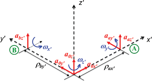
The coplanar 6a3ω configuration (called c6a3ω hereafter) with respect to a predefined coordinate system is shown in . In order to derive algebraic equations for angular acceleration in the c6a3ω configuration, the acceleration at each corner point (points A and B shown in ) with respect to the body fixed coordinate system can be determined as shown in Equations Equation(1)–(3):
(1)
(1)
(2)
(2)
(3)
(3) where
is angular acceleration in the body fixed frame; a is acceleration measured from accelerometers at each location; ω is angular velocity measured from ARS; and ρ is the distance between accelerometers at origin and accelerometers at points A and B.
Rearranging Equations Equation(1)–(3), angular acceleration can be expressed as
(4)
(4)
(5)
(5)
(6)
(6)
There is also an alternative way to calculate angular acceleration in the z′ direction (). The accelerometer installed at point A in the y′ direction can be installed instead at point B in the x′ direction. In that configuration, Equations (Equation4
(4)
(4) ) and (Equation5
(5)
(5) ) do not change but Equation (Equation6
(6)
(6) ) is replaced by Equation (Equation7
(7)
(7) ):
(7)
(7)
The detailed procedure for deriving the 3-dimensional kinematic equations with respect to the body fixed frame can be found in a previous study (Kang et al. Citation2011). In the current study, the configuration presented in , from which Equations Equation(4)–(6) were derived, was implemented on a newly designed fixture for the HIII 50 ATD.
Coplanar fixture design for HIII 50 head
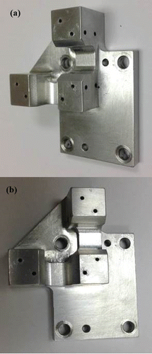
In order to validate the proposed c6a3ω configuration, a fixture was first designed for the HIII 50 head. The proposed fixture design was constrained by essential features such as the correct symmetrical placement of sensors, correct alignment with the HIII 50 head CG, minimization of mass, easy installation, and reduction of noise due to structural vibration. Several designs were proposed, and a modal analysis was conducted on several of them using commercial computer-aided design software (Solidworks, Dassault Systemes SolidWorks Corporation, Waltham, MA). A fixture that had higher fundamental natural frequency was preferred along with those that were simple to install. The final design was fabricated out of an aluminum alloy and had a mass of 64 g and a first natural frequency of 4,590 Hz (). Dimensional information of the proposed coplanar 6a3ω fixture was compared with the HIII 50 standard head CG mount (Figure A1, see online supplement). The c6a3ω configuration installed on the proposed fixture is shown in Figure A2 (see online supplement), and angular acceleration can be determined by using Equations Equation(4)–(6).
Validation testing setup and instrumentation
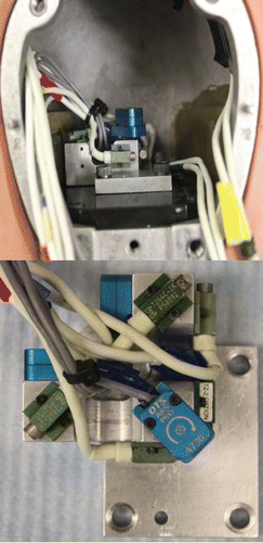
The newly designed c6a3ω fixture was placed at the CG of a HIII 50 head (). The c6a3ω configuration was composed of 6 accelerometers (7264C 2K, Endevco, San Juan Capistrano, CA) and 3 ARS (DTS ARS-18K, DTS Technologies, Seal Beach, CA). In addition, 9 accelerometers (7264C 2K, Endevco) installed on a tetrahedron fixture (tNAAP), as proposed by Yoganandan et al. (Citation2006), was externally mounted on the posterior surface of the HIII 50 skull cap (Figure A3, see online supplement). Because the tNAAP was intended to be used as a reference measurement system for angular acceleration, mounting it externally on the skull cap rather than using a specialized HIII 50 NAAP head was done to minimize possible errors in the kinematic calculations as a result of local skull deformation that can violate rigid-body kinematic theory.
The c6a3ω setup also allowed for comparison to the 3a3ω configuration (called i3a3ω hereafter) by subsequently treating the c6a3ω fixture as an i3a3ω fixture by only using accelerations and angular rates from select sensors. Thus, all 3 instrumentation methods were used to simultaneously undergo the impact event.
The head–neck apparatus was impacted at various high speeds and directions by a 23-kg pneumatic ram (Figure A4, see online supplement). This was done both with the neck secured to a fixed surface (i.e., lower neck was fixed to a test surface) as well as with sled trials (i.e., lower neck was secured to a mass on rails) where the apparatus was free to slide along rails in the direction of the ram impact. In each scenario, the impact angles were 30°, 45°, and 60° from the ram impactor moving direction (i.e., 0° is pure frontal impact; 90° is pure side/lateral impact) as shown in Figure A4. The impact location was approximately 75 mm above the CG location. For the fixed neck trials, the impact velocities were 1.5, 2.5, and 3 m/s, and for the sled trials the impact velocities were 1.5, 2.5, 3, and 3.5 m/s. Three repeated tests were conducted in each test condition, resulting in a total of 63 tests.
Data analyses
Data were sampled at 20,000 Hz. A fourth-order Butterworth low-pass filter in MATLAB (Mathworks, Natick, MA) corresponding to appropriate SAE J211 channel filter classes (CFCs) was applied to the data. For the tNAAP and c6a3ω configurations, the data recorded from the accelerometers and ARS were filtered at 1,650 Hz (CFC1000). The angular velocity for the i3a3ω configuration was first filtered at 1,000 Hz (CFC600) and then numerically differentiated to obtain angular acceleration. Angular acceleration for the tNAAP was calculated by employing the procedure proposed by Padgaonkar et al. (Citation1975), and that for the c6a3ω configuration was determined using Equations Equation(4)–(6). The kinematic data relative to the body fixed coordinate system on the external fixture were transformed to the body fixed coordinate system on the HIII 50 head using the procedure described in a previous study by Kang et al. (Citation2011). Origin locations and initial orientation of the body fixed coordinates for both the external tetrahedron fixture and the HIII 50 head were determined by digitizing points on the fixture and the head using a FaroArm device (Faro Arm Technologies, Lake Mary, FL). The normalized root mean square deviation (NRMSD) shown in Equation (Equation8(8)
(8) ) was used for quantitative evaluation of kinematic data from the proposed instrumentation configuration being evaluated. The NRMSD provides an average percentage error over time between the kinematic data from the instrumentation configuration being evaluated and a gold standard measurement. For this study, the gold standard chosen varied depending on the kinematic data being evaluated, with emphasis on using directly measured data (e.g., linear acceleration measured directly by accelerometers; angular velocity measured directly by ARS). If directly measured data were not available to be used as the gold standard then the gold standard was chosen to be either a calculated measure with (Equation1
(1)
(1) ) well-established accuracy in the literature (e.g., angular acceleration from tNAAP) or (Equation2
(2)
(2) ) the fewest computational operations (e.g., one numerical integration rather than 2 numerical integrations). In addition to the NRMSD, percentage differences of the peak values were calculated for each comparison being made because most injury criteria rely upon peak values.
(8)
(8) where n is the total number of data points and Y′max and Y′min represent the maximum and minimum values of the gold standard. Yi and Y′i are the ith data point obtained from the instrumentation configuration being evaluated and the ith data point obtained from the gold standard, respectively.
Results
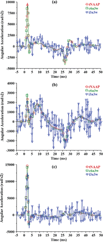
Time histories for x, y, and z angular acceleration with respect to the head body fixed coordinate system as determined from c6a3ω, i3a3ω, and tNAAP are shown in for an example test condition (45° fixed neck at 3 m/s impact). As seen in the figure, angular acceleration from the head impact tests is characterized by very short duration (around 3 ms) and high magnitude (approximately 15,000 rad/s2 in ).
Figure 4. Angular acceleration with respect to head body fixed coordinate system (45°, fixed neck, 3 m/s): (a) x direction, (b) y direction, and (c) z direction.
For quantitative analysis, the tNAAP angular accelerations were chosen as the gold standard because NAAP is a well-established and accurate method for calculating angular acceleration. For all directions, speeds, and neck fixtures, peak angular acceleration with respect to the x, y, and z body fixed head coordinate system and for all 63 tests is plotted in (c6a3ω vs. tNAAP in and i3a3ω vs. tNAAP in ), where the dotted line represents perfect agreement between the instrumentation configurations being compared, and the solid line is a linear regression model (slope 1 and intercept 0 indicating perfect agreement), showing correlation and fits between the configurations. The peak angular acceleration determined from the c6a3ω configuration shows good agreement with those from tNAAP, with most of the data being aligned with the dotted line (), whereas the peak angular acceleration calculated from the i3a3ω configuration shows more error and variation along the dotted line (). Uncertainty proposed by Bartsch et al. (Citation2014) is also provided in , showing that c6a3ω (5.6%) has lower uncertainty than i3a3ω (58.2%). The average NRMSD and peak differences between angular accelerations calculated using the c6a3ω/i3a3ω configurations and the angular accelerations calculated using the tNAAP configuration (gold standard) are shown in (all test conditions and x, y, and z components combined but separated by impact angle). For all 3 impact angles, both the NRMSD and peak differences for c6a3ω were less than 5%, but for i3a3ω the NRMSD was greater than 18% and the peak differences were greater than 20% (). The average NRMSD and peak differences for angular accelerations are also shown separated by x, y, and z components in Figure A5 (all test conditions combined; see online supplement).
Figure 5. Peak angular acceleration calculated from tNAAP (gold standard) vs. c6a3ω and i3a3ω for all 63 tests (triangle: 30° impact; circle: 45° impact; square: 60° impact; solid line: linear regression model; dotted line: perfect agreement between x and y values): (a) c6a3ω (algebraic) vs. tNAAP (algebraic): 5.6% of uncertainty and (b) i3a3ω (differentiated) vs. tNAAP (algebraic): 58.2% of uncertainty.
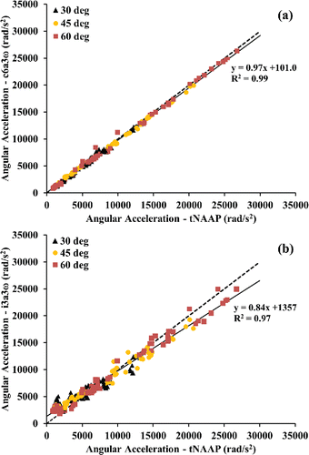
Figure 6. Average NRMSD and peak differences for angular acceleration (all test conditions and x, y, and z components combined, separated by impact angle): (a) Time history evaluation (NRMSD) c6a3ω vs. tNAAP <3% and i3a3ω vs. tNAAP > 18% and (b) peak evaluation c6a3ω vs. tNAAP <5% and i3a3ω vs. tNAAP > 20%.
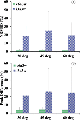
Figure A6 (see online supplement) shows a comparison of transformed resultant linear acceleration determined from (a) c6a3ω, (b) i3a3ω, and (c) tNAAP to the resultant linear acceleration directly measured by accelerometers at the origin of the opposite fixture (i.e., accelerations measured directly at the origin of the tNAAP fixture were considered the gold standard for the comparisons in Figures A6a and A6b; accelerations measured directly at the origin of the c6a3ω coplanar fixture were considered the gold standard for the comparison in Figure A6c; see online supplement). For transformed linear accelerations, the c6a3ω configuration demonstrates the highest correlation to directly measured accelerations as well as the lowest uncertainty of the three methodologies. Figure A7 (see online supplement) further demonstrates this, with the c6a3ω exhibiting average NRMSD and peak differences <3%, whereas the i3a3ω and tNAAP were less accurate (i3a3ω: average NRMSD <27% and average peak differences <20%; tNAAP: average NRMSD <2% and average peak differences <6%).
Because 6a3ω/3a3ω configurations have the advantage of directly measuring angular velocity (NAAP requires a numerical integration) and only requiring one numerical integration to get rotation (versus 2 numerical integrations for NAAP), the angular velocities and rotations calculated using tNAAP were evaluated. The gold standard for the angular velocity evaluation was directly measured angular velocity using the ARS on the c6a3ω fixture, and the gold standard for the rotation evaluation was c6a3ω rotation (because it requires the fewest computational operations). Average NRMSD and peak differences between angular velocity calculated from tNAAP and directly measured from ARS on the c6a3ω fixture were 4.2 and 7.9%, respectively, as shown in Figure A8a (see online supplement). For rotation, both NRMSD and peak differences using tNAAP were over 6% (Figure A8b; see online supplement).
Discussion
A method for computing 6DOF head kinematics of a rigid body using 6 accelerometers and 3 angular rate sensors installed in a coplanar configuration was described and evaluated in 30°, 45°, and 60° frontal impacts between 1.5 and 3.5 m/s with a 23-kg impactor. The proposed c6a3ω configuration requires only simple algebraic equations for calculating angular acceleration. These simple algebraic equations for the c6a3ω resulted in accurate angular acceleration when compared to the tNAAP as well as accurate transformed linear accelerations compared to directly measured linear accelerations. Average NRMSD and peak difference values for both angular acceleration and transformed linear acceleration were less than 5% for all 63 trials in various impact severities (energy: 26–141 J, linear resultant acceleration: 68–330 g, and angular resultant acceleration: 0.8–26.7 krad/s2).
It is clear qualitatively in that there is good agreement between c6a3ω and tNAAP angular acceleration, whereas i3a3ω produces very noisy angular acceleration signals. In fact, quantitative analysis of i3a3ω angular acceleration and transformed linear acceleration showed high levels of uncertainty and large values of NRMSD and peak value differences (–, A5–A7; see online supplement).
The c6a3ω configuration has the benefit of directly measuring angular velocity, whereas the NAAP requires numerical integration. The angular velocity determined from the tNAAP had an average peak difference over 7%, likely due to numerical integration error (Figure A8). Likewise, for measuring rotation, the c6a3ω configuration only requires one numerical integration, whereas NAAP requires 2 numerical integrations, which has been shown to be responsible for numerical errors (Kang et al. Citation2011; Nusholtz Citation1993; Padgaonkar et al. Citation1975; Voo et al. Citation2003), and NRMSD and peak difference values for tNAAP were both found to be >6% in this study. It is important to point out that the 3a3ω configuration yields results identical to those of the c6a3ω for angular velocity and rotation, indicating equally accurate assessments of measures like BrIC and head rotation. Only in the cases where angular acceleration or transformed kinematics in the global coordinate system are needed would the c6a3ω be preferred over 3a3ω because in those cases the 3a3ω requires numerical differentiation, which produces excessive noise in the angular acceleration signals (Kang et al. Citation2011, Citation2015). Even though the proposed c6a3ω configuration was developed and validated for high-energy impacts with high magnitudes in short durations, it should be applicable to general rigid-body motions with long durations due to its stability and simplicity of numerical processes.
The new fixture was designed for minimum size and weight. The weight (64 g) of the proposed c6a3ω fixture was only 7 g heavier than the HIII 50 standard head CG mount (57 g including the accelerometer block), so inertial properties of the head should be minimally affected. In order to make the head instrumentation and fixture as small as possible, efforts were made to reduce arm lengths, which are the distances between the CG accelerometers and the accelerometers at points A and B ( and A2; see online supplement). The arm length for the proposed fixture was 3.2 cm, which is shorter than any other head instrumentation fixtures published in the literature (Becker and Willems Citation1975; DiMasi et al. Citation1995; Kang et al. Citation2015; Martin et al. Citation1998; Yoganandan et al. Citation2006). This small arm length allowed the fixture to be installed directly at the CG of the HIII 50 head. The proposed fixture can also be installed in the HIII 5th percentile female head. The capability to install instrumentation at the head CG is very important for measuring ATD head kinematics because the ATD skull can sometimes deform during impacts with hard objects in crash tests. When this occurs, inaccurate rigid-body kinematics can result if accelerometers are installed peripherally on the skull (e.g., specialized NAAP head for HIII 50). The c6a3ω is a potential alternative to specialized NAAP heads due to its stability in numerical procedures, cost effectiveness, and insusceptibility of the effects of skull deformation.
In this study, the HIII 50 head was impacted at 30°, 45°, and 60° to focus on creating complex 3D head kinematics and evaluating the proposed configuration in these 3D impact scenarios. It was assumed that 2D kinematics yielded from the proposed configuration will be equally as accurate as the 3D kinematics, so impacts were not conducted in pure frontal (0°) and pure side/lateral (90°) conditions. Although it is possible that errors and uncertainty of the c6a3ω in the frontal and lateral impacts could be different from those in the oblique impacts (30°, 45°, and 60°), it is not likely, and if they do differ, the errors would likely be smaller for the less complex motion. The transform matrix was created using digitized points obtained from a FaroArm device. It was impossible to digitize the c6a3ω CG mount while installed inside the HIII 50 head so that external points were digitized to estimate the CG orientation and location. Though this could induce some errors in the transformation, the errors seem to be small given the good agreement between the c6a3ω transformed accelerations and the directly measured accelerations.
In summary, a new HIII 50 CG fixture using the c6a3ω configuration was developed and tested for the purposes of measuring 6DOF kinematics in high-magnitude head impacts. The benefits of this configuration are its ability to minimize the use of error-producing numerical methods, such as numerical integration and differentiation, often found in traditional sensor configurations. In high-magnitude impact scenarios, the c6a3ω was able to mimic the accuracy of the NAAP in measuring both linear and angular acceleration, with average NRMSD and peak difference values less than 5%, with 5.6% of uncertainty for all 63 trials. However, the average NRMSD and peak difference values between the i3a3ω and tNAAP were greater than 18 and 20%, respectively, with 58.2% uncertainty. For the transformed linear acceleration, the c6a3ω configuration had the highest correlation to directly measured acceleration with the lowest uncertainty of the 3 configurations (2.5% for the c6a3ω, 19.8% for the i3a3ω, and 4.6% for the tNAAP). The c6a3ω configuration also has the additional benefit of directly measuring angular velocity, whereas the tNAAP is less accurate because it requires a numerical integration, with NRMSD and peak differences in the 7–8% range for angular velocity and rotation (uncertainty of 4.3 and 6.7%, respectively). Therefore, the proposed c6a3ω is a potential advantageous alternative to the specialized NAAP heads due to its numerical benefits, cost effectiveness, and the elimination of the need to install sensors on the periphery of the skull.
Appendix
Download MS Word (1.5 MB)Acknowledgments
The authors thank Allison Guettler, Arri Willis, Alex Redrow, and Dr. Kyle Icke from the Injury Biomechanics Research Center (IBRC) for their considerable support during test days.
Funding
Financial support for this study was provided by the National Highway Traffic Safety Administration.
References
- Bartsch A, Samorezov S, Benzel E, Miele V, Brett D. Validation of an “intelligent mouthguard” single event head impact dosimeter. Stapp Car Crash J. 2014;58:14S–17S.
- Becker E, Willems G. An experimentally validated 3-D inertial tracking package for application in biodynamic research. Stapp Car Crash J. 1975;19:899–930.
- Bendjellal F, Oudenard L, Uriot J, Brigout C, Brun-Cassan F. Computation of Hybrid III head dynamics in various impact situations. Stapp Car Crash J. 1990;34:207–232.
- DiMasi FP, Eppinger RH, Bandak FA. Computational analysis of head impact response under car crash loadings. Stapp Car Crash J. 1995;39:425–438.
- Ewing CL, Thomas DJ, Majewski PL, Black R, Lustick L. Measurement of head, T1, and pelvic response to −Gx impact acceleration. Stapp Car Crash J. 1977;21:549–586.
- Faul M, Xu L, Wald MM, Coronado V. Traumatic Brain Injury in the United States. Atlanta, GA: Centers for Disease Control and Prevention, National Center for Injury Prevention and Control; 2010.
- Kang YS, Moorhouse K, Bolte JH. Measurement of six degrees of freedom head kinematics in impact conditions employing six accelerometers and three angular rate sensors (6aω configuration). J Biomech Eng. 2011;133:111007-1–111007-11.
- Kang YS, Moorhouse K, Bolte JH IV. Instrumentation technique for measuring six degrees of freedom head kinematics in impact conditions using six-accelerometers and three-angular rate sensors (6aω configuration) on a lightweight tetrahedron fixture. Paper presented at: 24th International Technical Conference on the Enhanced Safety of Vehicles (ESV); Gothenburg, Sweden, June 8–11, 2015.
- Krieger KW, Padgaonkar AJ, King AI. Full-scale experimental simulation of pedestrian–vehicle impacts. Stapp Car Crash J. 1976;20:431–463.
- Laughlin DR. A magnetohydrodynamic angular motion sensor for anthropomorphic test device instrumentation. Stapp Car Crash J. 1989;33:43–77.
- Martin PG, Hall GW, Crandall JR, Pilkey WD. Measuring the acceleration of a rigid body. Shock Vib. 1998;5(4):211–224.
- Nusholtz GS. Geometric methods in determining rigid-body dynamics. Exp Mech. 1993;33(2):153–158.
- Padgaonkar AJ, Krieger KW, King AI. Measurement of angular acceleration of a rigid body using linear accelerometers. J Appl Mech. 1975;42:552–556.
- Takhounts EG, Craig MJ, Moorhouse K, McFadden J, Hasija V. Development of brain injury criteria (BrIC). STAPP Car Crash J. 2013;57:243–266.
- Takhounts EG, Hasija V, Ridella SA, Rowson S, Duma SM. Kinematic rotational brain injury criterion (BRIC). Paper presented at: 22nd International Technical Conference on the Enhanced Safety of Vehicles (ESV); Washington, DC, June 13–16, 2011.
- Uhl RL, Rosenbaum AJ, Czajka C, Mulligan M, King C. Minor traumatic brain injury: a primer for the orthopaedic surgeon. J Am Acad Orthop Surg. 2013;21:624–631.
- Viano DC, Melvin JW, McCleary JD, Madeira RG, Shee TR, Horsch JD. Measurement of head dynamics and facial contact forces in the Hybrid III dummy. STAPP Car Crash J. 1986;30:269–289.
- Voo L, Merkle A, Chang SS, Kleinberger M. Comparison of Three Rotation Measurement Techniques in Rear Impact Application. Warrendale, PA: Society of Automotive Engineers; 2003. Paper No. 2003-01-0174.
- Yoganandan N, Zhang J, Pintar FA, Liu YK. Lightweight low-profile nine-accelerometer package to obtain head angular accelerations in short-duration impacts. J Biomech. 2006;39:1347–1354.

