
 ?Mathematical formulae have been encoded as MathML and are displayed in this HTML version using MathJax in order to improve their display. Uncheck the box to turn MathJax off. This feature requires Javascript. Click on a formula to zoom.
Abstract
Objective: The current state of the art human body models (HBMs) underpredict the number of fractured ribs. Also, it has not been shown that the models can predict the fracture locations. Efforts have been made to create subject specific rib models for fracture prediction, with mixed results. The aim of this study is to evaluate if subject-specific finite element (FE) rib models, based on state-of-the-art clinical CT data combined with subject-specific material data, can predict rib stiffness and fracture location in anterior-posterior rib bending.
Method: High resolution clinical CT data was used to generate detailed subject-specific geometry for twelve FE models of the sixth rib. The cortical bone periosteal and endosteal surfaces were estimated based on a previously calibrated cortical bone mapping algorithm. The cortical and the trabecular bone were modeled using a hexa-block algorithm. The isotropic material model for the cortical bone in each rib model was assigned subject-specific material data based on tension coupon tests. Two different modeling strategies were used for the trabecular bone.
The capability of the FE model to predict fracture location was carried out by modeling physical dynamic anterior-posterior rib bending tests. The rib model predictions were directly compared to the results from the tests. The predicted force-displacement time history, strain measurements at four locations, and rotation of the rib ends were compared to the results from the physical tests by means of CORA analysis. Rib fracture location in the FE model was estimated as the position for the element with the highest first principle strain at the time corresponding to rib fracture in the physical test.
Results: Seven out of the twelve rib models predicted the fracture locations (at least for one of the trabecular modeling strategies) and had a force-displacement CORA score above 0.65. The other five rib models, had either a poor force-displacement CORA response or a poor fracture location prediction. It was observed that the stress-strain response for the coupon test for these five ribs showed significantly lower Young’s modulus, yield stress, and elongation at fracture compared to the other seven ribs.
Conclusion: This study indicates that rib fracture location can be predicted for subject specific rib models based on high resolution CT, when loaded in anterior-posterior bending, as long as the rib’s cortical cortex is of sufficient thickness and has limited porosity. This study provides guidelines for further enhancements of rib modeling for fracture location prediction with HBMs.
Introduction
Traditionally, anthropometric test devices (ATDs) have been used to assess occupant injury risk, for example chest injury, in standardized car crashes. In recent years, as a complement, there is an increased use of detailed finite element (FE) human body models (HBMs). In ATDs, normalized chest compression is used in combination with a risk curve to estimate chest injury risk. Due to the fact that HBMs have more anatomical details compared to ATDs, HBMs facilitate the evaluation of injury at a higher level of detail. A detailed HBM model can at least in theory be used to predict rib fracture location and secondary soft tissue injuries, such as lung or liver lacerations.
The two major HBMs available today are Total HUman Model for Safety (THUMS) AM50 (Toyota Central R&D Labs. INC. (2018)) and Global Human Body Model Consortium (GHBMC) M50-O (Elemance). The thorax stiffness in these models has been validated for various loading conditions such as impactor tests and sled tests with post mortem human subjects (PMHS) (Shigeta et al. Citation2009, Li, Subit, Kindig, et al. Citation2010, Poulard et al. Citation2015, Vavalle et al. Citation2013, and Vavalle et al. Citation2015). Some studies have also compared HBM rib fracture predictions to PMHS test results (Shigeta et al. Citation2009, Schoell, Weaver, Urban, et al. Citation2015, and Schoell, Weaver, Vavalle, et al. Citation2015). It was shown that both HBMs underpredicted the number of rib fractures compared to the outcome of the PMHS tests. Thus, there is a need to further investigate how ribs should be modeled to enable rib fracture prediction.
In addition, some efforts have been made to create subject specific rib models for fracture prediction. Charpail et al. (Citation2005) performed anterior-posterior rib bending tests of 30 ribs. FE models were created for three out of these 30 ribs. The geometry for the models was based on clinical CT scans. The cortical bone was modeled using 4-noded thin shells and the trabecular bone using 8-noded solids. The authors found that the fracture locations, all laterally located, “corresponded with the experimental rupture sites”. In another study, Li, Kindig, Subit, et al. (Citation2010) used a similar test setup and modeling approach to create four subject specific ribs. The FE models predicted laterally located fractures for all four ribs. However, only one of the actual rib fractures were located laterally, meaning that only one fracture location was predicted accurately. The other three fractures were located anteriorly in the physical tests. In a follow-up study using the same anterior-posterior rib bending test setup, Li, Kindig, Kerrigan, et al. (Citation2010) modeled three subject specific ribs in detail. In addition to modeling the cortical bone using 4-noded thin shells as in the previous studies, the authors also created all-hexahedral versions of the three ribs using an octree-based hex meshing approach. The thin shell versions behaved similar to previous studies, i.e., the FE models predicted laterally located fracture sites. However, the actual fracture sites were all located anteriorly. The all-hexahedral rib models predicted the fracture location for two out of the three ribs. Thus, the all-hexahedral modeling approach seemed to provide some benefits over the thin shell modeling approach when considering fracture location prediction. However, as the study was limited to only three ribs there is a need to confirm these findings using a larger data set.
All of the studies on subject specific FE rib modeling mentioned above used averaged material data, either averaged from the dataset or from published data. There are several studies on rib material data (Kemper et al. Citation2005, Kemper et al. Citation2007, Subit et al. Citation2011 and Albert et al. Citation2017), showing large inter-subject variation in material parameters. Thus, the capability of a subject specific rib model to predict fracture location is likely to be enhanced by also including subject specific material data.
The aim of this study was to evaluate if subject-specific finite element (FE) all-hexahedral rib models, based on state-of-the-art clinical CT data combined with subject-specific material data from coupon testing, can predict the rib force-deformation response and fracture location in anterior-posterior bending.
Method
This study is based on twelve sixth level ribs, left or right, from twelve subjects, summarized in . The ribs were obtained through the Body Donation Program of the The Ohio State University and Lifeline of Ohio, and their procurement was satisfactorily reviewed by an ethics review board. Ribs were excised and stored at -20 C wrapped in normal saline soaked gauze prior to testing. Once thawed, all soft tissue was carefully removed while special attention was given to ensure the rib remained, see Agnew et al. (Citation2018) for all details of rib preparation and testing.
Table 1. Description of the subjects and ribs included in the study. All ribs are from rib level six.
Prior to testing, both rib ends were potted in 4 × 4 × 3 cm3 cups with Bondo® body filler (Bondo Corporation, Atlanta, GA, USA). Four strain gages were attached to the rib surface, two on the pleural surface and two on the cutaneous surface at 30% and 60% along the rib length axis measured from the posterior end (PSG1, PSG2, CSG1, and CSG2). Finally the rib potting material was attached to the potting brackets in the test apparatus, see . A pendulum, with a mass of 54 kg and initial velocity 2 m/s, impacted the right side rod pushing the anterior (sternal) rib end to the left. The anterior displacement was recorded using a linear string potentiometer and the rotation of the anterior and posterior rib ends using rotational potentiometers. The posterior reaction forces were measured using a 6-axis load cell.
Figure 1. Anterior posterior rib bending test setup. The left star indicates the location of a 6-axis load cell, and the right arrow indicates the path of a linear string potentiometer. The four asterisks represent the locations of the strain gages.
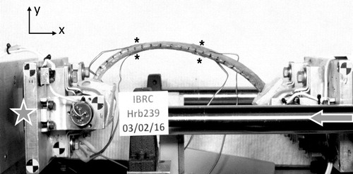
The geometry of each rib was captured using high resolution clinical computed tomography CT (Philips Ingenuity 64-slice), with an in-plane resolution of 0.146 mm and a slice thickness of 0.625 mm. In addition, after potting each rib was scanned using a high resolution hand held laser scanner (Faro Arm Technologies, Lake Mary, FL, USA), to quantify the exact relative location of the ribs in the pots.
The cortical bone mapping (CBM) algorithm presented by Holcombe et al. (Citation2018) was used to extract the periosteal and endosteal surfaces of the cortical bone from each rib. This algorithm re-samples the underlying CT image perpendicular to the rib’s surface to obtain a series of 1 D signals running across the cortex. It then fits a smoothed step-type 1-D model with three distinct regions (outside the cortex, within the cortex, inside the medullar cavity) to each resampled signal. As a collection, the transition points in each fitted step-model provide periosteal and endosteal surfaces of greater accuracy than can be obtained using traditional image thresholding.
In addition, bone tension coupons were fabricated from the ribs contralateral to those tested, as described in Albert et al. (Citation2017). Generally, one coupon was fabricated and tested for each subject. However, in case the material test was unsuccessful, a second coupon was fabricated and tested. The contralateral ribs did not undergo any injurious loading before undergoing material testing. The output from these material tests were subject specific tensile stress versus strain curves up to failure, as well as Young’s modulus, yield stress, yield strain, failure stress, and failure strain values.
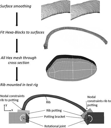
The development of the FE rib models started with smoothing of the surfaces from the CBM process (in particular the endosteal surface needed smoothing), see . Only the minimum amount of smoothing, necessary to ensure good mesh quality, was used. Rib Hrb244 needed some extra smoothing at 60% of the curve length, as the CT image was locally disturbed by a foreign object. Next, the geometry was decomposed using 3 D multi-blocks. The blocks were segmented to enable capturing of the change in rib geometry along the rib length and were filled with hexahedral elements. This meshing procedure created pure hexahedral meshed ribs fulfilling the element quality criteria suggested in Burkhart et al. (Citation2013). The number of elements in each rib ranged from 0.61 Million to 1.53 Million. To be able to capture local bending over the thickness of the cortical bone, three layers of solid elements were used over the cortex. More details can be found in Appendix A. Finally, each meshed rib was positioned in a FE representation of the anterior and posterior potting, using the geometries from the laser scans. The height of both cups were adjusted to correspond to the physical counterparts. Similar to the physical cups, the lower surface of the FE pots were rigidly attached to the potting brackets. A linear elastic material model with Young’s modulus 2.2 GPa was assigned to the pots. The sensitivity of this material parameter was investigated in a pre-study, showing marginal changes to the results when decreasing it by one order of magnitude. Each of the potting brackets were connected to either the loading or the support components using a revolute joint, see . Special care was taken to ensure that the rotational axis (around the z-axis) of the FE model was aligned to the physical rotational axis. The revolute joint was assumed to have no friction. The X-displacement of the anterior component was prescribed using the time history from the linear string potentiometer recorded in each physical test. The reaction force was measured on the posterior side, similar to the physical tests.
Figure 2. Modeling approach for the detailed subject specific ribs. The surfaces estimated using the CBM algorithm were first smoothed. Then the ribs were discretized using a semi-automatic Hexa-Block meshing procedure. This resulted in a high quality all hex mesh with 3 solid elements over the cortical bone thickness. Last, the rib was positioned in a model of the anterior posterior rib bending test apparatus.
The tensile material stress-strain curves were converted into true stress and logarithmic strain assuming a constant Poisson ratio of 0.5 in the plastic region. These curves were then used as input to an isotropic elasto-plastic material model (LS-DYNA MAT24 Hallquist Citation2006) for the cortical bone. No strain rate hardening of the yield surface was implemented. The trabecular bone was assigned a linear elastic material model and the material properties were estimated based on the bone volume fraction in a previous study by Maida (Citation2017) using the default regression models, relating bone volume fraction to mechanical properties, in the 3 D Image Segmentation and Processing Software ScanIP (Simpleware LTD Citation2017). The output from this software was one tetrahedral mesh for each rib with material properties for the trabecular bone divided into twenty levels. Using a python mapping algorithm (MapSolids.py Beta CAE Systems (2018)) the material definitions defined on the tetrahedral mesh were mapped over to the hexahedral trabecular bone mesh used in this study. The ribs developed using this technique are hereafter referred to as All Hex Map (AHM). In addition, to evaluate if the irregular distribution of trabecular bone stiffness/density affects the cortical bone strain, a second version of each rib was also created. For the second versions the Young’s modulus and mass density for the trabecular bone was homogenized into a single property using the Voigt assumption according to Eq. (1). The ribs developed using this technique are hereafter referred to as All Hex Voight (AHV).
(1)
(1)
Where n is the number of levels (here 20), υ is the volume and ω is the mass of each finite element.
The location for the fracture in the FE model was estimated as (any of) the position(s) for the 27 elements with highest first principle strain at the time for fracture in the physical test. The rationale for selecting 27 elements is that this is the number of elements that will be selected by adding all adjacent elements to the element with highest strain in a regular mesh of hexahedral elements, i.e., a 3 × 3 × 3 cube of elements, unless that element is located on the surface. For a well-defined strain hot-spot this will result in a single location. However, for a distributed strain field it is likely that the 27 elements will be distributed over several disjoint locations. As the ribs were subjected to anterior posterior end-to-end bending, and first principle strain was used as fracture criteria, only elements located on the cutaneous side were considered. Successful prediction of fracture location was based on closeness to actual fracture. It was decided that a fracture location metric (FLM) value, see Eq. (2), below 0.15 was considered successful. No element erosion was implemented.
(2)
(2)
To evaluate the kinetics and kinematics of the FE ribs the predictions were compared to the output signals from the physical ribs using CORA 3.6.1 (Gehre et al. Citation2009). Standard CORA settings were used. Rib end rotation and strain gage curves were compared between 5% and 95% of the time to fracture. Force-deformation curves were compared over the whole deformation interval except 3 mm in both ends.
All pre-processing was performed in ANSA version 18.1.1 (BETA CAE Systems, Switzerland) 2018 and all simulations were run in LS-DYNA MPP version 9.2 (LSTC, Livermore, CA). Post processing was performed in MATLAB version 2018a (Mathworks, Natick, MA)
Results
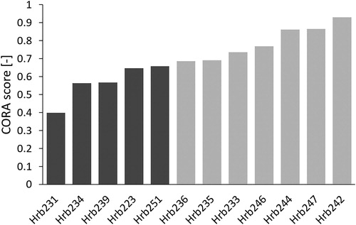
The CORA scores for the comparison of force time signals ranged between 0.40 (Rib Hrb231) to 0.93 (Rib Hrb242), with an average of 0.70. These results are presented for the AHM rib versions in , where the CORA scores are sorted in ascending order. Light gray bars represent CORA scores above or equal to 0.65, representing good biofidelity according to ISO/TR 9790, while scores below 0.65 are shown with dark gray bars. For many ribs represented by dark gray bars, the magnitude of the force time signal was considerably lower in the simulations than in the physical tests. The difference in kinetics and kinematics between the AHM and AHV rib versions were negligible. The full time histories can be seen in Appendix B.
Figure 3. CORA scores for force-deformation signals, sorted in ascending order. Dark gray bars represent CORA scores below 0.65 and light gray bars score above or equal to 0.65.
The average CORA score comparing the rotation of the anterior pot was 0.87 [0.79 to 0.95], while the average CORA score for the posterior pot was 0.97 [0.93 to 1.00]. Thus, the rotation of the posterior pot was almost perfectly reproduced, while the magnitude of the rotation of the anterior pot was underpredicted for all ribs. The average CORA scores for the four strain gages were: CSG1 0.91 [0.83 to 0.98], CSG2 0.91 [0.68 to 1.00], PSG1 0.81 [0.52 to 0.95] and PSG2 0.91 [0.69 to 1.00]. Out of the 4 × 12 = 48 strain gage results, all but five had CORA scores above 0.75.
In Appendix C, the fracture locations in the physical tests (jagged white lines) are compared to the first principle strain distribution, and the predicted fracture locations (white circle(s)). For six (Hrb231, 235, 242, 244, 246, and 247) of the rib models the fracture location was predicted accurately (0.0 < FLM < 0.15) independently of modeling strategy for the trabecular bone, while for four (Hrb 223, 234, 239, and 251) of the rib models it was not (0.19 < FLM < 0.44). For ribs Hrb233 and Hrb236 the fracture location was different depending on the modeling strategies of the trabecular bone (the AHM or the AHV version). The results are summarized in .
Table 2. Comparison of force biofidelity and fracture location predictability (FLM < 0.15). The ribs are sorted in ascending order with respect to the force CORA score (same as in ).
Discussion
The high CORA scores for rib potting rotations (average CORA for anterior 0.87 and posterior 0.97) and strain gages (average CORA scores 0.81-0.91) indicate that the rib kinematics were accurately predicted with the rib models. However, the CORA scores for the rib reaction forces, presented in , ranged from 0.40 to 0.93, which suggests that the rib kinetics were not accurately predicted for all ribs. These results can be further arranged into two groups. The first group, with “good biofidelity”, consisting of the ribs presented on the last seven rows in (ribs Hrb236, 235, 233, 246, 244, 247, and 242), with good or excellent reaction force predictions and accurate fracture location for at least one of the trabecular modeling approaches. The other group, with “poor biofidelity”, consists of the ribs presented on the first five rows in (ribs Hrb231, 234, 239, 223 and 251), and in this group neither the fracture location nor the reaction force were accurately predicted. For most of the ribs in the latter group (all but Hrb223), the force magnitude was underpredicted by more than 25%, as can be seen in Appendix B.
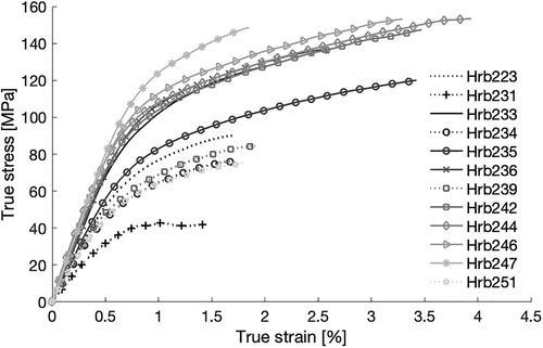
It was also observed that the ribs belonging to the poor biofidelity group had the weakest material response, as can be seen in the results from the coupon tests (). The stress-strain curves representing the poor biofidelity group are plotted using dotted lines. The tests indicate that the rib cortical bone in this group had lower Young’s modulus, lower yield stress, lower ultimate strain, and lower ultimate stress compared to the other ribs. This suggests that the ribs with poor biofidelity differ from the other ribs on a material level. On the other hand, it was also noticed that the average cortical thickness differs, with an average of 0.69 mm for the good biofidelity group and 0.60 mm for the poor biofidelity group, which indicates differences on structural level as well.
Figure 4. True stress-strain tensile curves used for the subject specific material data. Ribs represented with dark gray bars in are presented with dotted lines and ribs with light gray bars in with solid lines. Data obtained from tests performed and presented by Albert et al. (Citation2017).
Many studies have shown that although the individual variation is large, on average, rib cortical area decreases as function of age for adults (Sedlin et al. Citation1963, Epker et al. Citation1965, Takahashi and Frost Citation1966, Stein and Granik Citation1976). In addition McCalden et al. (Citation1993) showed that the cortical bone porosity increases with age, more for females than males, and that this change in porosity accounts for 76% of the reduction in material tensile strength in femora. This is in line with the current study, in which the average age at death for the subjects corresponding to the ribs belonging to the good biofidelity group was 68 years, while the average age for the subjects corresponding to the ribs belonging to the poor biofidelity group was 80 years. In addition, McCalden et al. (Citation1993), only found a marginal effect on material properties due to change in mineral content and concluded that “the quantitative changes in aging bone tissue, rather than the qualitative changes, influences the mechanical competence of the bone”. In this study cortical volumetric bone mineral density (vBMD) was calculated via CT scan as a proxy for mineral content, and no trend with successful or unsuccessful predictions was found. This is in line with the results from Hunter et al. (Citation2019), in which the authors found vBMD to be a poor predictor of rib structural properties.
In this study the cortical bone was treated as a continuum solid and the cortical area was estimated based on the CBM algorithm. In previous work, CBM has achieved sub-pixel accuracy in bone thickness estimations (Treece et al. Citation2010), and specifically for rib cortices, an accuracy (mean thickness error) and precision (standard deviation error) of −0.03 ± 0.17 mm was obtained using CT images of 0.373 mm/pixel. The current study uses CT voxel sizes of 0.146 × 0.146 × 0.625 mm, where the CBM accuracy ± precision have been shown to be −0.013 ± 0.17 mm (Holcombe et al. Citation2019). Nevertheless, with fractures likely occurring near vulnerable bone regions with very small cortices in the order of 0.1-0.2 mm, even this sub-millimeter error can potentially influence fracture outcome. In the current study smoothing of the CBM generated surfaces was applied in an attempt to remove local bumps.
Further, modeling a cortical bone as a continuum, when it in reality includes intracortical porosity, will lead to an overestimation of the true area. Dominguez et al. (Citation2016) found that accounting for intracortical porosity, rather than assuming a solid cortex, in the same rib experiments as described here allowed for improved predictive strength of structural properties. In the presence of intracortical porosity, the remaining material will in reality get a higher stress compared to a material without pores. However, as the intracortical pores were not captured by the CBM method, and thus were not included in the FE model, this stress concentration will not be included in the models. For high levels of intracortical porosity the localized stress (around the pores) can be very high, leading to fracture even if the nominal stress is quite low. This means that the fracture can occur at a location away from the area with maximum nominal stress. A higher level of intracortical porosity and heterogeneous cortex can be one reason the fracture location was not predicted accurately for about half of the ribs in this study.
Also the trabecular bone was treated as a continuum solid. Two rib models were created for each rib, one with homologous material properties (AHV) and one in which the variance in linear stiffness of the trabecular bone was estimated using a regression model, taking the CT-based variation in a bone volume fraction as input (AHM). The difference in whole rib kinetics and kinematics of the two trabecular bone modeling approaches was negligible. However, for some ribs (Hrb223, 233, 236, 246, and 251) there were some differences in the strain distribution between the two modeling approaches, see Appendix C. This indicates that the trabecular bone properties can influence the rib fracture location. However, the current solid element representation is probably too coarse to properly model the spatial variation in trabecular bone stiffness.
Rib fracture in this study was estimated based on first principle strain. It has previously been shown that cortical bone has different failure properties in different loading conditions, and can be considered to be transversely isotropic (Reilly and Burstein Citation1975). In particular, the tensile yield and failure stress are typically lower than the compressive yield and failure stress (Currey Citation1970), Reilly and Burstein Citation1975). During the anterior-posterior rib bending, the cutaneous cortex will be subjected to tensile stress and the pleural to compressive stress, and the principle stresses and strains will line up along the long rib axis. It has also been shown that the cutaneous cortex is generally thinner (Agnew et al. Citation2018) and has more intracortical porosity (Agnew and Stout Citation2012, Dominguez and Agnew Citation2014, and Dominguez and Agnew Citation2016) compared to the pleural cortex. Together this means that the fracture initiation will most likely be in tension on the cutaneous side and the first principle strain is a good candidate for fracture prediction in this load case.
The accuracy of the fracture location estimation was judged by the value of the FLM, where values below 0.15 was considered to correspond to an accurate fracture location estimation. The ribs belonging to the good biofidelity group had a FLM ranging from zero to 0.15, while the FLM for the ribs belonging to the poor biofidelity group ranged from 0.19 to 0.44 (except Rib Hrb231 which had a low FLM but a poor reaction force response). A perfect correlation between predicted fracture location and actual fracture location is not feasible, as this would most likely require a level of detail that is not possible to implement. Given an area of similar stress level, the actual fracture location will be determined by very small imperfections. However, the fracture location accuracy could also be discussed in terms of clinical relevance. The correlation between rib fractures and organ injuries have previously been studied (Thor and Gabler Citation2008, Park Citation2012, Kelbaugh Citation2015, and Rostas et al. Citation2017). In these studies fracture location was classified according to location (Left/Right) and level (High/Mid/Low). In addition Kelbaugh (Citation2015) also classified the fracture location along the rib according to the method proposed by Ritchie et al. (Citation2006). In this method, the ribs are divided into five 36° sectors (anterior, anterior-lateral, lateral, posterior-lateral, and posterior), corresponding to 20% of the rib length in each slice (disregarding that part of the anterior sector is occupied with the sternum and cartilage). This method has also been used in Lee et al. (Citation2015) to analyze fracture patterns in real life crashes. A FLM of 0.15 will not guarantee that the predicted fracture location from the simulation will be in the same sector as in the physical test, but the order of discretization is similar, so rib models of that accuracy should be comparable to real life data processed according to this methodology.
High intracortical porosity in combination with a thin cortical cortex can also be problematic when creating tensile coupons for material testing. After the milling and sanding operations described in Albert et al. (Citation2017) the final sample thickness is 0.36 ± 0.08 mm. High levels of porosity can make the sample hard to handle during testing, with an increased risk of introducing test artifacts. However, extreme care was taken with these samples during fabrication and testing to minimize any potential artifacts. In addition, the resulting stress-strain curve will be calculated assuming that the bone is solid, as the external width and thickness dimensions of the gage length used to calculate area were measure with calipers. Intracortical porosity can lead to an underestimation of the actual stress in the material. As the group for which the fracture location was not accurately predicted had lower yield stress and ductility in conjunction with lower failure strain compared to the other group, this likely supports the hypothesis that these ribs have a higher level of intracortical porosity. The current study indicates that the subject specific all-hex modeling approach, based on high resolution CT data processed using the CBM method, using subject specific material can predict rib fracture location in anterior-posterior bending for ribs with low levels of intracortical porosity. For older subjects with high levels of intracortical porosity, additional research needs to be carried out to develop the best structural or material modeling approach. Future research will explore precise quantification of intracortical porosity and microstructural variation in rib coupons to further validate this explanation.
FE rib models consisting of hundreds of thousands or millions of elements cannot practically be used in full HBM models. The rationale of this study was rather to study if very detailed geometrical ribs could predict fracture location, and if so, the next step will be to analyze what simplifications could be implemented without losing predictability. One example is to analyze how much the mesh can be coarsened and if the cortex can be simplified, e.g., using thick or thin shell elements.
Limitations
There are several limitations to this study. Despite using high resolution clinical CT and novel methods for analysis, there is still uncertainty in estimating cortical thickness. This is particularly important for areas of thin cortex, as the relative error is magnified here. In addition, intracortical pores are not detected in either the CT data or the CBM algorithm, and could not be incorporated into the FE model, meaning that the effective thickness of the cortex will be overestimated. Another limitation is that the ribs are only tested in anterior-posterior bending. In reality the rib deformation can be more complex, for example including shear, torsion and bending components (Mendoza-Vazquez et al. Citation2013). A related limitation is that an isotropic material model was used. In reality the cortical bone can be considered to be transversely isotropic (Reilly and Burstein Citation1975). However, for this simplified test setup the loading is only anterior-posterior bending, which will align the principle stress and strain along the rib length axis. This is the same alignment as for the tensile material coupons, which justifies the use of an isotropic material model in this study. However, for another load scenario, it might be important to include a more refined material model for accurate fracture prediction.
Supplemental Material
Download Zip (1.5 MB)Acknowledgments
The authors would like to thank FFI-Strategic Vehicle Research and Innovation, by Vinnova, the Swedish Energy Agency, the Swedish Transport Administration and the Swedish vehicle industry for funding (parts of) this work through the project 2015-04864 Development of Implementable Omni-Directional Chest and Spine Injury Criteria for Human Body Models. The authors also thank the staff at the Beta CAE Nordic office for excellent support on the morphing compatibilities in ANSA. This work was carried out at SAFER- Vehicle and Traffic Safety Centre at Chalmers, Sweden. We are very grateful to the anatomical donors for their gifts to further scientific inquiry, without which this research would not have been possible. The authors would also like to thank Randee Hunter and Karen Briley for their assistance with CT scanning and vBMD calculation of ribs, and all staff and students from the Injury Biomechanics Research Center, especially Rakshit Ramachandra and Arrianna Willis.
Related Research Data
References
- Agnew AM, Murach MM, Dominguez VM, Sreedhar A, Misicka E, Harden A, Bolte JH, Kang Y-S, Stammen J, Moorhouse K, et al. 2018. Sources of variability in structural bending response of pediatric and adult human ribs in dynamic frontal impacts. Stapp Car Crash J. 62:119–192. Nov
- Agnew AM, Stout SD. 2012. Brief communication: reevaluating osteoporosis in human ribs: the role of intracortical porosity. Am J Phys Anthropol. 148(3):462–466.
- Albert DL, Kang Y-S, Agnew AM, Kemper AR. 2017. A Comparison of Rib Structural and Material Properties from Matched Whole Rib Bending and Tension Coupon Tests. Paper presented at: International IRCOBI Conference; September 13-15; Antwerp, Belgium.
- ANSA version 18.1.x User's Guide 2018. [computer program]. Switzerland
- Burkhart TA, Andrews DM, Dunning CE. 2013. Finite element modeling mesh quality, energy balance and validation methods: a review with recommendations associated with the modeling of bone tissue. J Biomech. 46(9):1477–1488.
- Charpail E, Trosseille X, Petit P, Laporte S, Lavaste F, Vallancien G. 2005. Characterization of PMHS ribs: A new test methodology. Stapp Car Crash J. 49:183
- Currey JD. 1970. The mechanical properties of bone. Clin Orthop Relat Res. 73(6):210–231.
- Dominguez VM, Agnew AM. 2014. Patterns in resorptive spaces in elderly rib cortices. Am J Phys Anthropol. 153:107–107.
- Dominguez VM, Agnew AM. 2016. Examination of factors potentially influencing osteon size in the human rib. Anat Rec (Hoboken). 299(3):313–324.
- Dominguez VM, Kang YS, Murach MM, Crowe N, Agnew AM. 2016. Bone area vs cortical area: considering intracortical porosity when predicting rib structural properties. Paper presented at: International IRCOBI Conference; September 14–16; Malaga, Spain.
- Elemance. Virtual Human Body Models. [Accessed 2018 Nov 26]Available at: http://www.elemance.com/virtual-human-body-models/..
- Epker B, Kelin M, Frost H. 1965. Magnitude and location of cortical bone loss in human rib with aging. Clin Orthop Relat Res. 41:198–203.
- Gehre C, Gades H, Wernicke P. 2009. Objective rating of signals using test and simulation responses. Paper presented at: The 21st Annual Enhanced Safety of Vehicles; June 15–18, Stuttgart, Germany.
- Hallquist J. O. 2006. LS-DYNA theory manual. Livermore, California: Livermore Software Technology Corporation.
- Holcombe SA, Hwang E, Derstine BA, Wang SC. 2018. Measuring rib cortical bone thickness and cross section from CT. Med Image Anal. 49:27–34.
- Holcombe SA, Kang YS, Derstine BA, Wang SC, Agnew AM. 2019. Regional maps of rib cortical bone thickness and cross‐sectional geometry. J Anat. doi:10.1111/joa.13045
- Hunter R, Kang HS, Briley K, Agnew AM. 2019. Feasibility of volumetric bone mineral density (vBMD) to predict rib structural properties. Am J Phys Anthropol. 168: 110.
- Kelbaugh CL. 2015. Rib fracture patterns in fatal motor vehicle accidents [Masters thesis]. Tampa (FL): Department of Anthropology, University of South Florida.
- Kemper AR, McNally C, Kennedy EA, Manoogian SJ, Rath AL, Ng TP, Stitzel JD, Smith EP, Duma SM, Matsuoka F, et al. 2005. Material properties of human rib cortical bone from dynamic tension coupon testing. Stapp Car Crash J. 49:199–230.
- Kemper AR, McNally C, Pullins CA, Freeman LJ, Duma SM, Rouhana SM. 2007. The biomechanics of human ribs: material and structural properties from dynamic tension and bending tests. Stapp Car Crash J. 51:235–273.
- Lee EL, Craig M, Scarboro M. 2015. Real-world rib fracture patterns in frontal crashes in different restraint conditions. Traff Inj Prev. 16(sup2):S115–S123. 10.1080/15389588.2015.1062888
- Li Z, Kindig MW, Kerrigan JR, Untaroiu CD, Subit D, Crandall JR, Kent RW. 2010. Rib fractures under anterior-posterior dynamic loads: experimental and finite-element study. J Biomech. 43(2):228–234.
- Li Z, Kindig MW, Subit D, Kent RW. 2010. Influence of mesh density, cortical thickness and material properties on human rib fracture prediction. Med Eng Phys. 32(9):998–1008.
- Li Z, Subit D, Kindig M, Kent R. 2010. Development of a Finite Element Ribcage Model of the 50th Percentile Male with Variable Rib Cortical Thickness; Paper presented at: The thirty-Eight International Workshop. Injury Biomechanics Research.
- Maida A. 2017. Modélisation des côtes humaines en Flexion antéropostérieur [Master thesis], Villetaneuse (France): The Institut Scientifique et Polytechnique Galilée.
- McCalden RW, McGeough JA, Barker MB, Court-Brown CM. 1993. Age-related changes in the tensile properties of cortical bone. The relative importance of changes in porosity, mineralization, and microstructure. J Bone Joint Surg Am. 75(8):1193–1205.
- Mendoza-Vazquez M, Brolin K, Davidsson J, Wismans J. 2013. Human rib response to different restraint systems in frontal impacts: a study using a human body model. Int J Crashworthiness. 18(5):516–529.
- Park S. 2012. Clinical analysis for the correlation of intra-abdominal organ injury in the patients with rib fracture. Korean J Thorac Cardiovasc Surg. 45(4):246.
- Poulard D, Kent RW, Kindig M, Li Z, Subit D. 2015. Thoracic response targets for a computational model: a hierarchical approach to assess the biofidelity of a 50th-percentile occupant male finite element model. J Mech Behav Biomed Mater. 45:45–64.
- Reilly DT, Burstein AH. 1975. The elastic and ultimate properties of compact bone tissue. J Biomech. 8(6):393–405.
- Ritchie NL, Wang SC, Sochor MR, Schneider LW. 2006. A method for documenting locations of rib fractures for occupants in real-world crashes using medical computed tomography (ct) scans: SAE Technical Paper; 0148-7191.
- Rostas JW, Lively TB, Brevard SB, Simmons JD, Frotan MA, Gonzalez RP. 2017. Rib fractures and their association with solid organ injury: higher rib fractures have greater significance for solid organ injury screening. Am J Surg. 213(4):791–797.
- Schoell SL, Weaver AA, Urban JE, Jones DA, Stitzel JD, Hwang E, Reed MP, Rupp JD, Hu J. 2015. Development and validation of an older occupant finite element model of a mid-sized male for investigation of age-related injury risk. Stapp Car Crash J. 59:359–383.
- Schoell SL, Weaver AA, Vavalle NA, Stitzel JD. 2015. Age-and sex-specific thorax finite element model development and simulation. Traffic Inj Prev. 16(sup1):S57–S65.
- Sedlin ED, Frost HM, Villanueva AR. 1963. Variations in cross-section area of rib cortex with age. J Gerontol. 18(1):9–13.
- Shigeta K, Kitagawa Y, Yasuki T. 2009. Development of next generation human FE model capable of organ injury prediction. Paper presented at: The 21st Annual Enhanced Safety of Vehicles; June 15–18, Stuttgart; Germany.
- Simpleware LTD. Simpleware Reference Guide 2017. [computer program]. Innovation centre rennes drive, Exeter, United Kingdom: Simpleware LTD.
- Stein I, Granik G. 1976. Rib structure and bending strength: an autopsy study. Calc Tissue Res. 20(1):61–73.
- Subit D, de Dios EP, Valazquez-Ameijide J, Arregui-Dalmases C, Crandall J. 2011. Tensile material properties of human rib cortical bone under quasi-static and dynamic failure loading and influence of the bone microstucture on failure characteristics. arXiv preprint arXiv:1108.0390v2.
- Takahashi H, Frost HM. 1966. Age and sex related changes in the amount of cortex of normal human ribs. Acta Orthop Scand. 37(2):122–130.
- Thor C, Gabler H. 2008. The relationship between thoracic organ injuries and associated rib fractures. Biomed Sci Instrum. 44:292
- CORA Release 3.6 User’s Manual 2012. [computer program]. Gaimersheim, Germany: PDB - Partnership for Dummy Technology and Biomechanics;
- Toyota Central R&D Labs. 2018. INC. Human Body Models for Injury Analysis THUMS®. [Accessed 2018 Nov 26]. Available at: https://www.tytlabs.com/tech/thums/index.html..
- Treece GM, Gee AH, Mayhew P, Poole KE. 2010. High resolution cortical bone thickness measurement from clinical CT data. Medical Image Analysis. 14(3):276–290.
- Vavalle NA, Davis ML, Stitzel JD, Gayzik FS. 2015. Quantitative validation of a human body finite element model using rigid body impacts. Ann Biomed Eng. 43(9):2163–2174.
- Vavalle NA, Moreno DP, Rhyne AC, Stitzel JD, Gayzik FS. 2013. Lateral impact validation of a geometrically accurate full body finite element model for blunt injury prediction. Ann Biomed Eng. 41(3):497–512.