
 ?Mathematical formulae have been encoded as MathML and are displayed in this HTML version using MathJax in order to improve their display. Uncheck the box to turn MathJax off. This feature requires Javascript. Click on a formula to zoom.
Abstract
Objective
In this research, body technology was established for side collisions with new IIHS MDB as a representative case. In the conventional body structure, most of the load received from the barrier is absorbed by bending deformation of the door beam and B-pillar, etc. For that reason, the body is subjected to large deformation before reaching the maximum load, and the deformation increases further when subjected to a high-energy collision. Therefore, the objective of this research is to create a structure that increases the load from the initiation of impact and suppresses the deformation of the car body.
Method
An arched door beam was developed to reduce the bending moment by the axial load in the longitudinal direction generated during the deformation and to increase the load in the lateral direction. A principle equation was developed that uses the shape of the door beam as a variable. A prototype of the arched door beam was fabricated, and its performance was evaluated by an impactor test. A full-car simulation was conducted using a mass-produced sedan as a base, to which the arched door beam was added to verify the performance of the complete vehicle.
Results
The results of the impactor tests were evaluated using the load gradient, which was defined as the generated load divided by the amount of deformation. Compared to conventional straight door beams, the load gradient was 7.1 times higher. Full-car simulation results showed that for a gasoline-powered vehicle body weight, the body load gradient of the proposed structure was 4.7 times higher, and the body deformation adjacent to the dummy shoulder was reduced by 210 mm. Spine acceleration of the dummy was reduced by 56%.
Conclusion
The body structure proposed in this research has the effect of increasing the load gradient and reducing body deformation and spine acceleration. It is expected to be applicable to EVs and FCVs, which require more energy absorption due to their increased vehicle weight.
Introduction
The Insurance Institute for Highway Safety is conducting ongoing research focusing on the correlation between safety performance scores and fatality rates (IIHS Citation2019) and plans to apply a new test standard (henceforth, the new IIHS MDB) to increase vehicle safety in side-impact crashes (IIHS Citation2020).
The new IIHS MDB will feature a significant change in the configuration of deformable barriers. Previously, barriers with a constant surface pressure over the entire surface were used. The new barrier, however, has a non-uniform surface pressure distribution, and the edge of the barrier corresponding to the front side frame has been partially strengthened. As a result, the test standard was able to reproduce actual accidents, such as the penetration of a door into the interior of a vehicle. With the addition of changes in barrier weight and barrier speed increases, impact energy has been increased by 80% (Becky and Arbelaez Citation2021). Safety performance is evaluated based on three parameters: dummy injury value, restraint system performance (head protection), and structure. Structure is defined as a parameter that evaluates the distance between the maximum deformation position of the B-pillar and the center of the seat. In the conventional body structure, most of the load received from the barrier is supported by the bending deformation of the door beam and B-pillar, and thus a large deformation occurs before the maximum load is reached.
Previous research on side impacts includes deformation mode prediction (Inokuchi et al. Citation2018), weight reduction by applying HOT-stamped materials (Fukuchi and Nomura Citation2015), and 980 MPa-class high-tensile strength steel material (Pednekar et al. Citation2020). In each case, there has been no significant evolution in the vehicle body structure. Hasegawa et al. (Citation2022) reported that a new load path was created in the B-pillar that can support the lateral input from the barrier as an axial load in the downward direction of the vehicle body, thereby increasing the load from the initiation of the collision and reducing bending deformation. In addition to the results of this B pillar research, we aimed to further enhance the body structure.
In the future, the total weight of vehicle will tend to increase due to the shift to EVs and FC vehicles. Assuming an accident between these vehicles, the deformation of the vehicle is expected to be even larger due to the increased collision energy. While meeting the evolving safety standards of the times, it is also necessary to respond to demands for enhanced fuel economy through weight reduction of the vehicle.
In light of these current circumstances, the new IIHS MDB, which is the most high-energy test standard at present, was used as a representative case study. The objective of this research was to construct a structure with a high load gradient (load divided by deformation) that increases the load from the initial impact and reduces deformation of the vehicle body. As mentioned earlier, the new IIHS MDB will have higher strength at the edges of the barriers, thus increasing the importance of the door beams. When a conventional straight door beam receives an input from the barrier, it is challenging to generate high loads with small deformation because it is subjected to bending deformation like that of a simply supported beam at both ends that receives a concentrated load in the center. The challenge was to construct a door beam structure that reduces the bending moment and increases the load gradient by utilizing the axial load generated during deformation. A designed door beam was fabricated and evaluated in an impactor test. Full-car simulation was also conducted to evaluate body deformation and injury values of the dummy.
Method
Arched door beam structure
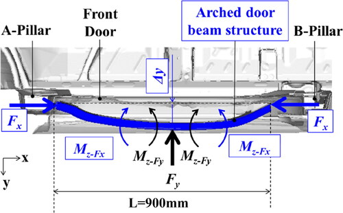
The basic principle of increasing the load gradient KBM of a door beam is to apply moment balancing to reduce the bending moment Mz-Fy with the axial load Fx generated when the door beam is deformed.
A schematic diagram is shown in . The door beams have an arched shape that protrudes outward from the vehicle like a bumper beam. When the door beam is subjected to a lateral load Fy from the barrier, it is extended in the x direction of the vehicle body while being bent in the lateral direction. The bending moment Mz-Fy generated in the door beam at this time is reduced by the moment Mz-Fx in the opposite direction, which is the product of the axial load Fx generated at the front and rear ends and the length Δy projecting in the lateral direction. The principle equations are shown below.
Figure 1. Schematic diagram of loads and moments acting on arched door beam structure.
First, Mz-Fy generated by lateral load Fy is expressed as EquationEq. (1)(1)
(1) , where L is the length of the door beam and C is a constant determined by the door beam support conditions.
(1)
(1)
Next, the moment Mz-Fx in the opposite direction to Mz-Fy is expressed as follows.
(2)
(2)
When M is the bending moment at the center of the arched door beam, it can be expressed as
(3)
(3)
If it is assumed that the lateral load Fy reaches its maximum value Fy-max when M reaches the fully plastic moment M0 of the door beam cross-section, Fy-max is obtained by substituting EquationEqs. (1)(1)
(1) and Equation(2)
(2)
(2) into EquationEq. (3)
(3)
(3) .
(4)
(4)
From EquationEq. (4)(4)
(4) , Fy-max depends on the support conditions in the first term of the right-hand side and is proportional to the product of Fx and Δy in the second term. In other words, Fy-max can be increased by increasing Mz-Fx.
Impactor test
To verify the accuracy of the Fy-max estimation of the principle equation and demonstrate that the arched door beam increases the load gradient KBM, an impactor test was conducted. A diagram of the test conditions is shown in , which was a horizontal launch test in which a 200 mm × 200 mm impactor was impacted at the center of the specimen. The door beam was mounted on a vertical surface, and load cells were installed at the fixation points in both ends of the beam to measure Fy. Displacement of the impactor, which was considered equivalent to the deformation of the door beam, was measured by laser displacement sensor. Fy divided by displacement of the impactor is the load gradient KBM at maximum load.
Figure 2. Set up for impactor test of door beam.
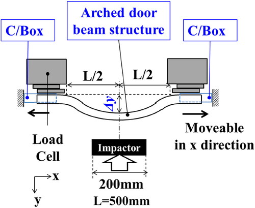
The test conditions are shown in the Appendix (see Table A1, Supplementary Material). Two test patterns were conducted: Test A using a straight beam and Test B using an arched door beam with a Δy of 70 mm. The arched door beam comprises three parts, including crash boxes at both ends. The crash boxes were fabricated with 590 MPa-grade high-tensile-strength steel material, and three different thicknesses of 1.2, 1.6, and 2.0 mm were used to check whether the Fy-max increases with an increase in Fx. The support condition for Test A was free of rotation around the z-axis, and the support condition for Test B was rotation-constrained around the z-axis and free of displacement in the x-direction.
Full-car simulation
A full-car simulation was performed to verify that the overall vehicle load gradient KCAR was enhanced and that the body deformation and injury values were reduced.
Three analysis models were investigated. The first model was the 2018 Honda Accord (hereinafter referred to as BASE). In the second model, the arched door beam and B-pillar load transfer mechanism (Hasegawa et al. Citation2022) were installed in the BASE model (hereinafter referred to as NEW-PET). For the third model, the weight of the vehicle body was increased to 2800 kg, which is considered equivalent to an EV (hereinafter referred to as NEW-EV). Assuming that the maximum weight of a C-category gasoline vehicle when converted to an EV is 2800 kg, the weight is evenly distributed at each mesh node on the front floor where the battery is mounted. Crash simulations were conducted using LS-DYNA in accordance with the new IIHS MDB test standards.
The contact load between the vehicle and the barrier divided by the body deformation next to the dummy shoulder was calculated as the body load gradient KCAR, and also evaluated by the Structure. Upper and lower spine acceleration (henceforth, Aspine) were evaluated by injury measure. The dummy acceleration a (here ASpine) is expressed by EquationEq. (5)(5)
(5) using the three variables VDR, Ld and AMDB (Mizuno Citation2012). These variables respectively represent the door intrusion velocity, the total deformation of the door interior and the deflection of the dummy, and the deceleration of the barrier. To verify the effect of arched door beams in relation to injury values using EquationEq. (5)
(5)
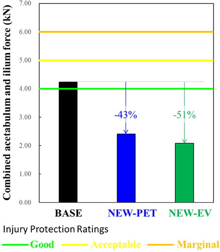
(5) , ASpine was used as a measure of injury value. Average rib deflections and combined acetabulum and ilium force combine forces, which are directly related to ratings, were also evaluated.
(5)
(5)
The arched door beams were positioned at an angle that declines from the A-pillar side to the B-pillar side, so that the rear end is at the same height as the load transfer mechanism installed in the B-pillar. The door beam was designed and positioned to fit in the door panel and not to inhibit the opening and closing of the window. The length L and the protrusion Δy were set at 900 mm and 85 mm, respectively.
Results
Impactor test
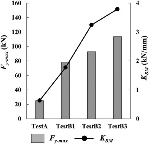
The results of the Fy-max and KBM obtained from the impactor test are shown in . The bar graph represents the Fy-max and the line graph represents the KBM. Compared to Test A with a straight beam, Test B with an arched door beam structure had higher Fy-max and KBM. In Test B3, which had the highest KBM enhancement in Test B, Fy-max was 4.5 times higher and KBM was 7.1 times higher than in Test A. The Fy-max predicted by the principle equation and the test results are shown in the Appendix (see Table A2, Supplementary Material). In Test B, the difference between the prediction and the test results was up to 75 kN.
Figure 3. Comparison of Fy-max and KBM for straight and arched beams.
The deformation of the arched door beam is shown in the Appendix (see Figure B1, Supplementary Material). Test B1, which has the thinnest C/Box and the greatest deformation, is shown as a representative diagram. Axial crushing of the C/Box can be observed.
Full-car simulation
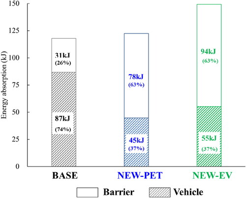
The relationship between the load and the deformation for the full-car simulation is shown in . The left side of the graph represents the deformation of the vehicle body, and the right side represents the deformation of the barrier. The dotted line represents the BASE, the solid line represents the NEW-PET, and the single-dotted line represents the NEW-EV. Contact force divided by deformation of the vehicle body is the load gradient KCAR at maximum deformation as shown in the plot in . KCAR was calculated as 0.6 kN/mm for BASE, 4.7 times higher (2.8 kN/mm) for NEW-PET, and 3.5 times higher (2.1 kN/mm) for NEW-EV. The results of energy absorption percentage are shown in . Comparing the BASE with the proposed structure, the percentage of energy absorption of the vehicle body was reduced from 74% to 37%.
Figure 4. Comparison of contact force-stroke curves.
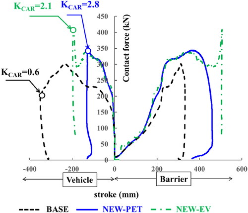
Figure 5. Comparison of energy absorption rates.
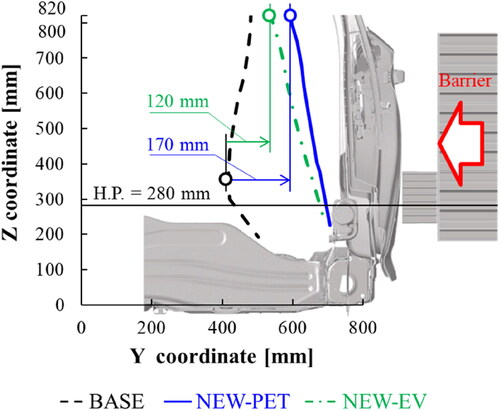
The maximum deformation diagram of the door panel observed in the Y-Z Section next to the dummy shoulder is shown in . Compared to the BASE, the deformation was reduced by 220 mm for NEW-PET and 170 mm for NEW-EV. shows the results of evaluating Structure. Comparing the intrusion of NEW-PET and NEW EV against BASE, it was reduced by 170 mm and 120 mm, respectively.
Figure 6. Comparison of door deformation of dummy shoulder section.
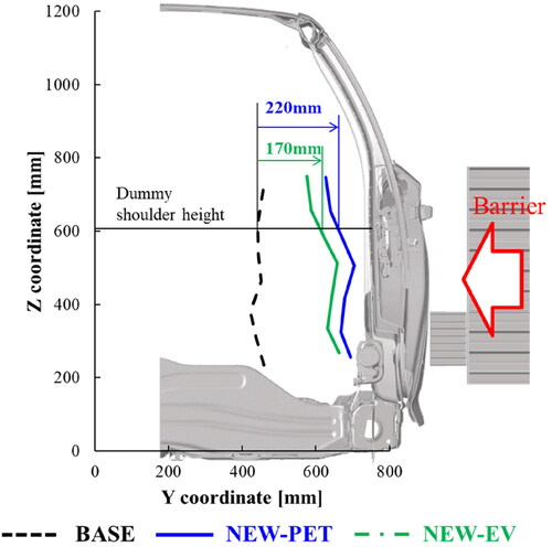
Figure 7. Comparison of structure.
The maximum values of Aspine are shown in . Compared to BASE, ASpine-LWR of NEW-PET and NEW EV was reduced by 56% and 58%, respectively. The average deflection values of ribs are shown in . Compared to BASE, average rib deflection of NEW-PET and NEW EV was reduced by 73% and 76%, respectively. The average rib deflection value of NEW-PET is 15 mm below the upper limit of the IIHS Good rating. The maximum values of combined acetabulum and ilium force are shown in . Compared to BASE, combined acetabulum and ilium force of NEW-PET and NEW EV was reduced by 43% and 51%, respectively. The combined acetabulum and ilium force value of NEW-PET is 1.59 kN below the upper limit of the IIHS Good rating.
Figure 8. Comparison of Aspine.
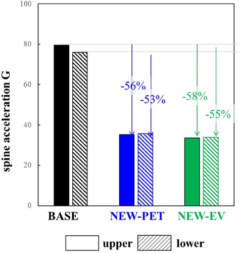
Figure 9. Comparison of average rib deflection.
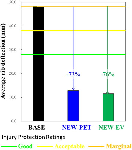
Figure 10. Comparison of combined acetabulum and ilium force.
Discussion
Differences between impactor test results and basic principle equation
This section discusses the causes of the difference in load between the principle equation and the impactor test values and corrects the principle equation to enhance the accuracy of the initial design study.
In EquationEq. (4)(4)
(4) , Δy represents the initial dimensions of the arched door beam projecting outward from the vehicle. As it is pushed by the impactor and deforms, its projection length decreases. When the door beam generates the maximum load, the deformation averages 34 mm for Test B1 to B3, representing a 50% change from the initial Δy. Since the maximum load is proportional to Δy, this deviation is considered to be shown as a load difference.
Therefore, the initial protruding length was redefined as Δy0, the deformation at maximum load was set as Δs, and the principle EquationEq.(4)(4)
(4) was corrected to EquationEq. (6)
(6)
(6) .
(6)
(6)
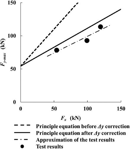
A comparison of the test results and the corrected equation was done, and the relationship between Fy-max and Fx is shown in . The dotted line represents the principle equation before the correction, the solid line represents the principle equation after the correction, the points represent the test results, and the single dotted line is the linear approximation of the test. For Δs, the average value of 34 mm from Test B1 to B3 was used. In the principle equation before correction, the difference between the Fy-max in the principle equation and in the test results widened as Fx increased, but the correction of Δy0 reduced this difference. The slope of the approximate line in the test results was 0.50, while it was 1.12 in the principle equation before the correction and 0.57 after the correction, indicating a better reproducibility of the loading trend.
Figure 11. Comparison diagram of the principle equation before and after correction and the impactor test.
With correction EquationEq. (6)(6)
(6) from EquationEq. (4)
(4)
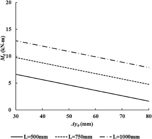
(4) , if Δy0 is smaller than Δs, the second term on the right side becomes negative. In other words, the limitation for dimendion is to make Δy0 larger than Δs. The next limitation is to avoid the window-lifting mechanism and the door-lock mechanism. Furthermore, the rear end of the door beam should be positioned at the same height as the load transfer mechanism in order to enhance load transfer from the arched door beam to the B-pillar. In addition, typical dimensions that vary with vehicle design are door length and door width, which are affected by L and Δy0 of the arched door beam. Assuming Fy-max = 100 kN, Fx = 100 kN, and Δs = 34 mm, the relationship between L, Δy0, and M0 is shown in . It can be seen that when L is long and Δy0 is small, M0 becomes large, and when L is short and Δy0 is long, M0 becomes small. The shape and cross-sectional strength of the arched door beam can be designed according to these vehicle dimensions.
Figure 12. Relationship diagram between dimensions and M0 of arched door beam.
From the above, Fy-max became principle equation enhanced accuracy at the initial design stage by adding correction of deformation amount Δs to y0.
Mechanism of KCAR increasing in full-car simulation
Considering each part of the vehicle frames as a spring, the vehicle body is composed of a combination of springs in series and parallel. In this case, KCAR will be the spring constant of the whole vehicle body system. The mechanism by which KCAR was increased in the full-car simulation is discussed by relating the KCAR to the load gradient of the main frames to which the load is transmitted.
First, it was verified that the load gradient KDR of the door was enhanced. Loads were measured at both ends of the door beam and door outer panel by the Section Force, and the door deformation was evaluated as the difference in the deformation between the door panel next to the Dummy shoulder and the B pillar lower. A diagram of the relationship between load and stroke is shown in the Appendix (see Figure B2(a), Supplementary Material). The line type of the graph is the same as in . The KDR of BASE was 0.3 kN/mm, while that of NEW-PET was 1.5 kN/mm and that of NEW-EV was 1.2 kN/mm. As in the door beam test, KDR was enhanced.
Next, the load gradient KBPLR of B-pillar, to which the door beam load is transferred, was verified. The Appendix (see Figure B2(b), Supplementary Material) shows a diagram of the relationship between load and stroke. KBPLR is 2.5 kN/mm for NEW-PET and 2.3 kN/mm for NEW-EV, compared to 0.5 kN/mm for BASE.
The load distribution from B-pillar to the Upper body (Steering-Hanger, Roof-Crossmember-front, and Roof-Crossmember) and Underbody (Floor-Crossmember and Mid-Floor Crossmember) was then confirmed. As shown in the Appendix (see Figure B3, Supplementary Material), the Underbody axial load increased for NEW-PET and EV compared to BASE. The load gradient is also higher for members subjected to axial load than in the bending direction, and the load gradient of the Crossmember was more than 30 kN/mm, which was higher than that of the KDR and KBPLR.
Considering simply the vehicle body as a three-element series spring that transfers loads in the order of door, B-Pillar, and Underbody, KCAR is expressed as EquationEq. (7)(7)
(7) . Here, KUNB is load gradient of the underbody.
(7)
(7)
Using EquationEq. (7)(7)
(7) , the ratio of increase in KCAR to BASE was calculated to be 4.9 times for NEW-PET and 4.1 times for NEW-EV, which is generally consistent with the increasing trend as in the simulation results.
From the above verification results, KCAR can be regarded as the spring constant of a simplified series spring, and therefore KCAR is affected by a weak spring. Increasing KCAR requires increasing both KDR and KBPLR. In this simulation, the arched door beam and the load transfer mechanism of B-Pillar were able to respectively increase the load gradient. Therefore, it is considered that the KCAR was enhanced.
Mechanism of aspine decreasing in full-car simulation
The results of full-car simulation show that spine acceleration can be reduced by increasing KCAR with the proposed structure. In this section, the trend of Aspine predicted by full-car simulation was verified by comparing it with the value calculated from the theoretical equation.
A graph of the time history of the four variables for full-car simulation is shown in the Appendix (see Figure B4, Supplementary Material). The Aspine of BASE increased rapidly after 20 ms, and the VDR was about 10 m/s at the maximum Aspine value of 32 ms. On the other hand, the Aspine of the proposed structure rose slowly and reached a maximum at about 55 ms. The VDR is also reduced by approximately 25% to 35% compared to BASE. Since the VDR affects the Aspine as a square from EquationEq. (7)(7)
(7) , the estimated Aspine reduction effect of the door is about 45% to 55%. For Ld and AMDB, as for VDR, we measured the results at the Aspine maximum timing (plotted in ) and compared the Aspine calculated using EquationEq. (7)
(7)
(7) with the Aspine of the full-car simulation (Table B3). Although the absolute Aspine differs by about 8 m/s,2 the trend in the percentage reduction of ASpine from BASE is generally consistent.
From the above, increasing KCAR reduces the body deformation and slows the door intrusion velocity. Consistent with the theory of decreasing ASpine, the tendency of the full-car simulation to predict ASpine seems to be reliable.
Prospects for the future
This section discusses further prospects for this research theme in light of future changes in the transportation situation, including demographics and the EV shift.
First, explain our views on demographics. The population is aging, and by 2050, 15% of the world’s population is expected to be aged 65 or older. In addition, improvements in the standard of living and medical care have increased healthy life expectancy, and the elderly are able to drive themselves and lead active lives. However, cognitive functions such as vision decline with age, which may increase the number of accidents involving elderly drivers. Furthermore, it has been reported that the risk of chest injury tends to increase with age, and this tendency is more pronounced in women (Sugaya et al. Citation2019). In this study, we obtained the prospect that increasing KCAR decreases body deformation and reduces Aspine and chest deflection. The results of this study are expected to be highly effective as one of the methods to protect elderly people with reduced impact resistance, and we would like to utilize the results of this study in the development of new evaluation criteria for the protection of elderly people, in addition to the evaluation of Sid2s for adult women using the IIHS MDB.
Next, let us assume an accident between EVs. As mentioned above, the vehicle body weight of EVs increases due to the installation of large-capacity batteries. In order to respond for the ODB and SOB test standards for frontal as well as side collisions, it is necessary to increase the amount of energy absorbed by the motor compartment, and the main frames, such as the front-side frames, are likely to be reinforced. In the case of an accident in which the EV is the first vehicle concerned, the deformation and occupant injury of the second vehicle concerned in a side impact can be expected to increase due to the strengthened motor compartment. To prepare for accidents between EVs, which could be a future issue, increasing KCAR will also enhance the defensive capability of the second vehicle concerned and relatively reduce the aggressiveness of the first vehicle concerned. The arched door beam transfers the load to the Underbody via the load transfer mechanism of the B-Pillar. The Underbody of EVs is strengthened according to the standard for battery protection in the event of Pole side impact. This means that the Underbody can more easily support the load of the arched door beam, making it a good match for EVs.
In the future, we would like to conduct simulations using the strength of the KCAR and motor compartment as parameters to evaluate compatibility. In addition to our research, we will also work with other automakers to deeply analyze accident patterns between vehicles and further evolve and standardize vehicle body structures.
In conclusion, the technical details are summarized below.
Under the IIHS MDB test conditions, a structure with a high load gradient was devised to increase the load from the initiation of the crash and to reduce the deformation of the vehicle body. The door beam was designed as an arched shape. The following conclusions were obtained from this structure.
Impactor tests demonstrated that the load gradient KBM of an arched door beam was enhanced.
Full-car simulations predicted an increase in load gradient KCAR and a reduction in vehicle body deformation.
Full-car simulations predicted reduced ASpine.
The body structure proposed in this research is expected to be applied to EVs and FCVs, which require more energy absorption due to their increased vehicle weight, as well as to various other categories.
Supplemental Material
Download Zip (40.4 MB)Disclosure statement
The authors have nothing to disclose.
Funding
The author(s) reported there is no funding associated with the work featured in this article.
References
- Becky CM, Arbelaez RA. 2021. Developing an aluminum honeycomb barrier to represent a striking SUV in a side impact crash test. Traffic Inj Prev. 22(7):582–587. DOI: 10.1080/15389588.2021.1955252.
- Fukuchi H, Nomura N. 2015. Automotive solution development of hot stamping with high productivity. Shinnittetsu Sumikin Giho. 402:70–72.
- Hasegawa A, Takeuchi R, Yamada H, Fujii T. 2022. B-pillar load transfer mechanism in side collision. Honda R&D Tech Rev. 34(1):88–97.
- Inokuchi J, Yamamae Y, Yasuki T. 2018. Investigation of Reduced model for displacement mode of center pillar in SUV side impact. Trans Soc Automot Eng Jpn. 49(2):359–364.
- Insurance Institute for Highway Safety. 2019. Next steps for the IIHS side crashworthiness evaluation program. SAE Technical Paper. 2019-SC18-22-0002.
- Insurance Institute for Highway Safety. 2020. Side impact crashworthiness evaluation 2.0 crash test protocol (version I) version 1. Available at: https://www.iihs.org/media/0027a26d-8dd2-4de4-affc-0eb98338c6ba/cLjh9w/Ratings/Protocols/current/test_protocol_side-2.0.pdf. Accessed August 2020.
- National Highway Traffic Safety Administration: Injury criteria for side impact dummies 2004. Available at: https://www.nhtsa.gov/. Accessed May 2004.
- Mizuno K. 2012. Crash safety of passenger vehicles. Japan: The University of Nagoya Press, p. 181–185.
- Pednekar V, Pereira A, Ballard A, Chen G, Komarivelli R, Li H. 2020. Structural Performance Comparison between 980 MPa Generation 3 Steel and Press Hardened Steel Applied in the Body-in-White A and B-Pillar Parts 2020 SAE Technical Paper 2020-01-0537.
- Sugaya H, Takahashi Y, Gunji Y, Dokko Y, Ayyagari M, Whitcomb B, Markusic C, Agnew A, Kang Y-S, Bolte J. IV. 2019. Development of a human fe model for elderly female occupants in side crashes. 26ESV, 19-0052.