
 ?Mathematical formulae have been encoded as MathML and are displayed in this HTML version using MathJax in order to improve their display. Uncheck the box to turn MathJax off. This feature requires Javascript. Click on a formula to zoom.
Abstract
Objective
This research focused on FMVSS301, which is required for higher energy absorption as a regulation for rear-end collisions. Since they are offset collisions, the deformation of the non-collision side frame, which does not directly contact the barrier, is less than on the collision side. The reason is that the rear bumper beam with curvature is deformed into a straight shape by the load from the barrier, resulting in an asymmetrical load distribution from the barrier that is biased toward the collision side. Therefore, the objective of this research was to construct a new bumper beam structure that reduces the difference in the load input to both frames and increases the energy absorption of the non-collision side frame.
Method
The basic principle is to generate a counterforce against the lateral loads during transmitting the load from barrier to the frames. To achieve this, a bow-shaped rear bumper beam structure was devised. The rear bumper beam corresponds to the bow and the newly added connection plate to the string. The lateral load increase is suppressed and load distribution to the rear frame is maintained.
Results
The designed rear bumper beam and rear components equipped with the rear bumper beam were both prepared and evaluated by drop test. With testing of the rear bumper beam, it was demonstrated that the load in the lateral direction, which conventionally generates over 80 kN, could be canceled. Tests of the rear component demonstrated that load distribution to the rear frame could be maintained, and the energy absorption of the non-collision side frame could be enhanced by 35 times. The total energy absorption of the barrier and the two frames was demonstrated to increase 2.9 times.
Conclusion
The bow-shaped rear bumper beam was designed to distribute the load evenly to the collision and non-collision side frames, and to deform both frames, thereby achieving a higher energy absorption of the entire vehicle body. This is expected to be applicable to electric vehicles and FCVs, which require more energy absorption with increased vehicle weight.
Introduction
Acceleration of shifting to electric vehicles is expected toward achieving a carbon neutral society. High-voltage units such as large-capacity batteries and drive motors are mounted on the front and rear floors and are required by law to be protected from ground fault during side-pole or rear-end collisions. The collision speeds specified in the side pole protocol are the same with all regions, but the collision speed specified for rear-end protocols are different from each region. While the speed specified in the protocol with Europe or Asia is 50 km/h, for North America 80 km/h (NHTSA Citation2014) is specified in FMVSS301R (hereinafter referred to as “301”). This paper is focused on rear-end collisions with test protocol 301, as a representative case study for the larger energy absorption needed.
The 301 protocol is specified as a 70% offset collision with a deformable barrier (hereinafter referred to as “barrier”). In conventional rear body structures, most of the crash energy is absorbed by the frame on the collision side that is impacted by the barrier, and the non-collision side frame that is not impacted by the barrier has less deformation. The rear bumper beam, which has curvature, is deformed in a straight shape due to the load from the barrier, resulting in an asymmetrical condition where the contact area from the barrier is biased toward the impacted side. In addition, the change in load from the deformable barrier to the vehicle is also large, and this makes it challenging to realize a crushing deformation with high energy absorption efficiency with the collision side of the frame only.
Compared to conventional vehicles, the weight is increased for an electric vehicle. The momentum and energy conservation laws indicate that an increase of vehicle weight from 1500 kg to 2800 kg, approximately an additional 45 kJ, is required to be absorbed under the 301 protocol conditions. In general, the high-voltage unit of an electric vehicle is larger than the fuel tank of a conventional vehicle and is located in the rear area of the vehicle. Therefore, the space that can be deformed and absorb energy during a collision is expected to be reduced. Moreover, electric vehicles need to enhance energy absorption efficiency, while it is also necessary to respond to the need for enhanced fuel economy through weight reduction of the vehicle.
Research related to rear-end collision issues includes the application of high-tensile strength steel, such as hot-stamped materials (Fukuchi and Nomura Citation2015) and lambda materials with reduced fracture (Maki and Takaki Citation2017) and rear bumper beam designed in aluminum (Paulsen and Welo Citation2002) or plastic (Yabu and Yasuhara Citation2018) in the field of materials. From structural research, there is a circular frame to increase energy absorption of the rear floor pan (Yasuhara and Egawa Citation2008). It has been reported in a recent paper that the load can be evenly transferred to the frame by revising the bumper beam shape (Hasegawa et al. Citation2020). Considering the deformation characteristics of the barrier, this was respectively demonstrated experimentally in the lower- and higher-load ranges up to and above 120 kN. Furthermore, using a test specimen in which the rear bumper beam is combined with the rear frame, it has been verified to the point where the energy absorption of the rear frame on the non-collision side is enhanced (Hasegawa et al. Citation2020). However, the research on the combined rear bumper and rear frame component is limited to the low-load range under conventional vehicles.
The bumper beam is the essential structural component that receives the first input from the barrier and transfers the load to the vehicle body. In addition, this can be applied to both conventional vehicles and electric vehicles. In order to enhance further energy absorption of the vehicle, the objective of this research is to construct a rear bumper beam structure that can increase and maintain the load distributed to the collision- and non-collision-side frames. A new structure was added to suppress the lateral load that occurs when the rear bumper beam deflects, thereby preserving its shape, and also to increase the longitudinal load. The effect of new structure was evaluated by the prototype bumper beam in a drop test.
Method
Bow-shaped rear bumper beam structure
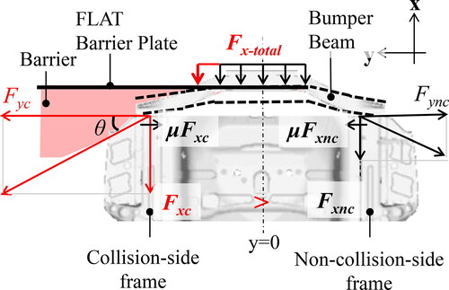
shows a schematic diagram of the trapezoidal rear bumper beam, with the central portion protruding rearward. When the rear bumper beam is pushed by the barrier from behind, longitudinal and lateral loads are generated. The respective longitudinal and lateral loads on the collision side are Fxc and Fyc. The respective longitudinal and lateral loads on the non-collision side are Fxnc and Fync. Also note the sum of Fxc and Fxnc as Fx-total. As mentioned above, the lateral load is higher for electric vehicles, which require high longitudinal loads. As the lateral load increases, the rear bumper beam deforms in a straight line as shown by the dotted line, and the contact area with the barrier extends beyond the central flat area. The input from the barrier becomes asymmetrical, and it is assumed that the load is not uniformly transmitted to the left and right frames. Furthermore, if lateral load is applied to the rear frame, the buckling mode of the rear frame becomes unstable due to bending momentum, resulting in reduced energy absorption. Therefore, it is necessary to suppress the lateral load to maintain load distribution in the high-load range.
Figure 1. Rear bumper beam deformation diagram.
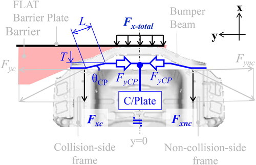
Based on the higher-load range of the rear bumper as reported by Hasegawa (Hasegawa et al. Citation2020), a bow-shaped rear bumper beam structure (hereafter referred to as “bow-shaped structure”) was devised to naturally generate a counter-force against the lateral load during transmission of the load to the frames. A schematic diagram is shown in . The rear bumper beam corresponds to the bow, and the newly added Connection Plate (hereinafter referred to as “C/Plate”) to the string. When the rear bumper beam is pushed from behind by the barrier, the C/Plate is subjected to a medial load, FyCP, which is generated in the opposite direction of the Fyc and Fync, and the two loads cancels each other out to suppress lateral deformation and maintain load distribution. At this moment, to increase the Fx-total, the C/Plate is required to have sufficient strength to withstand the accompanying increase in Fyc and Fync.
Figure 2. Schematic diagram of bow-shaped rear bumper beam structure.
The basic equations of the bow-shaped structure are shown below. Because the load is symmetrical, the variables are representative of the collision side. Defining θ as the angle of the slope of the beam, the relationship between Fxc and Fyc is shown in EquationEq. (1)(1)
(1) .
(1)
(1)
Fyc is expressed by EquationEq. (2)(2)
(2) using the coefficient of friction μ between the beam and the rear frame.
(2)
(2)
Assuming that the yield stress of material used in C/Plate is σ and the cross-sectional area is A, EquationEq. (3)(3)
(3) must be satisfied so that C/Plate is designed based on yield strength of the material.
(3)
(3)
EquationEqs. (1)-(3) can be used to determine the cross-sectional area of the C/Plate according to the assumed Fxc. shows C/Plate with a trapezoidal shape that was adopted for the actual design space in the vehicle. The C/Plate is designed to avoid interference with the rear panel and other parts, and to maintain a specific amount from the rear panel. The shape of the C/Plate can be defined by three parameters: the amount of protrusion T, inclined surface length L, and the inclination angle θCP, starting from the horizontal part where the rear bumper beam is joined to the rear frames.
Drop test
Rear bumper beam and rear component tests were conducted to verify the effect of the bow-shaped structure. The bow-shaped structure was tested as Test01 to verify the effect of the design to suppress lateral loads. Test01 was compared to a high-load bumper without C/Plate (hereafter referred to as “HL”) (Hasegawa et al. Citation2020). The trapezoidal shape of the C/Plate was prepared with a 7000 series of aluminum of 5.0 mm thickness and welded to the rear bumper beam.
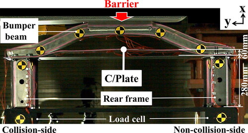
The component was tested as Test02 to verify that load distribution could be maintained on the collision- and non-collision-side frames and that the two frames were equally deformed. The rear component comprises the bow-shaped structure used in Test01, rear panel, and the two rear frames. The rear frames were prepared by using 980 MPa-grade high-tensile strength steel with a thickness of 1.2 mm, The cross-section of frames is 85 × 90 mm consisting of two parts with a length of 280 mm, assuming a deformable length for an electric vehicle. Two tests based on a C-category sedan reported by Hasegawa (Hasegawa et al. Citation2020) were used for comparison of energy absorption. The first is a test with conventional bumper beam (CONV01), and the second is a test with bumper beam structure, which is capable of distributing load into both frames in the lower-load range (CONV02).
Each test was conducted in a drop test facility that was capable of measuring the load with a load cell. shows a diagram of the test configuration. The test specimen was fixed to a flat surface plate and a barrier was attached to the drop weight. The barrier was free-fallen with an offset of 70% between the barrier and the specimen. Load cells were placed under the specimen to measure the load in the x and y directions. In component Test02, the timing when C/Plate generated the lateral load was measured by strain gauges. The deformation of components was captured by a high-speed camera, and its amount was calculated by image analysis of a target mark attached to the specimen. The energy absorption was calculated from the load of the load cell and the displacement of the target mark. Details of the test conditions are described in the Appendix (see Table A1, Supplementary Material).
Figure 3. Set up for drop test of rear component.
Results
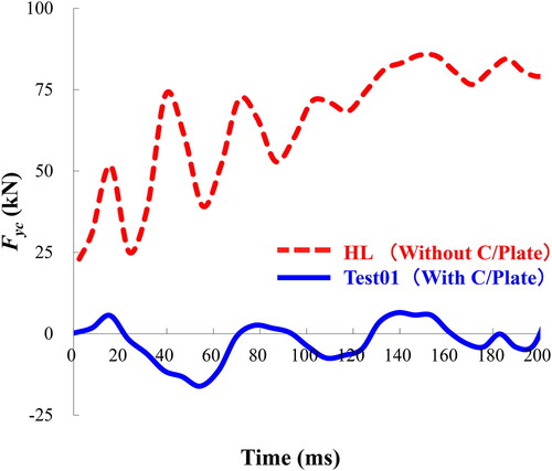
Lateral load in rear bumper drop test (Test01)
shows the time histories of the Fyc obtained from the drop test with the rear bumper beam. The solid line shows the result from the bow-shaped structure (With C/Plate) and the dotted line shows the result from HL (Without C/Plate). The bow-shaped structure, to which C/Plate is added canceled out the Fyc, which had risen to over 70 kN without the C/Plate.
Figure 4. Fyc Comparison with and without C/Plate.
Effect of C/plate on component drop test (Test02)
The test result from bow-shaped structure confirmed that C/Plate is capable of suppressing lateral loads.
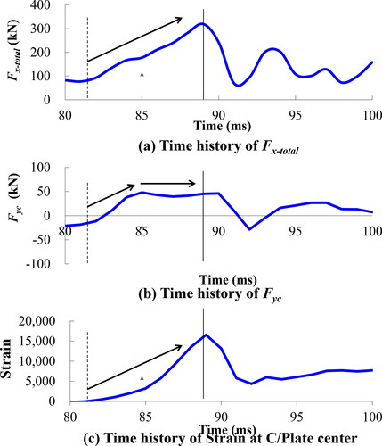
The timing by which FyCP was generated is verified from the rear component test result. shows the time history of Fx-total, Fyc, and strain measured at the center of the C/Plate, respectively (see Supplementary Material). After 80 ms, when Fx-total started to increase, the strain on C/Plate also started to increase. On the other hand, Fyc also started to increase from 80 ms, but stopped increasing and remained from 85 ms. This is considered to be an indication that C/Plate was fully extended and started generating a load at 85 ms. In other words, it is considered that the rise of Fyc was suppressed by the generation of lateral load by the C/Plate. There was no rupture at the C/Plate, and its deformation did not interfere with the generated lateral load.
Figure 5. Timing of increase in Fx-total, Fyc, and C/Plate strain for Test02.
Left and right frame deformation for rear component drop test (Test02)
shows an illustration of the tested component with Test02. Respective deformation of the collision-side and non-collision-side frames were 139 mm and 150 mm.
Figure 6. Photograph of rear component Test02 after drop test.
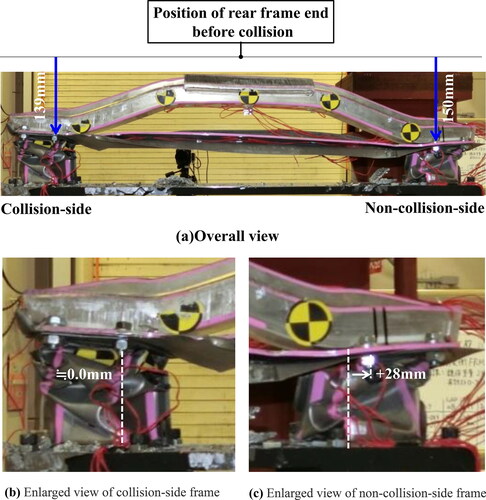
are enlarged respective views of the collision-side and non-collision-side frames. The y-displacement of the frames was measured with respect to the inner wall of the frames. The y-displacement of the collision-side frame was almost 0 mm and that of the non-collision-side frame was 28 mm.
Energy absorption of left and right frames (Test02)
shows the energy absorption of the collision- and non-collision-side frames and barrier in the rear component test.
Figure 7. Comparison of energy absorption.
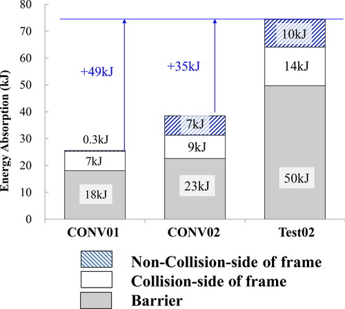
14 kJ and 10 kJ were respectively absorbed by the collision-side and non-collision-side frames, a difference of 4 kJ. The total energy absorption in Test02 was 24 kJ, which was 3.6 times higher than CONV 01 and 1.5 times higher than CONV02. Energy absorption by the non-collision-side frame was 35 times higher than CONV01, and 1.4 times higher than CONV02. Similarly, the total energy absorption by the two frames and barrier was 2.9 times higher than CONV01, and 1.9 times higher than CONV02.
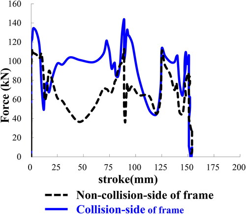
Energy absorption was calculated by integrating the force and stroke diagram shown in . The stroke was measured by image analysis of the target mark, which was fixed to the frame. However, it could not be measured at the collision side frame as the barrier had covered the target mark during the deformation. Since the difference in deformation between the collision- and non-collision-side frames was less than 15%, the deformation on the two frames was assumed to be the same as on the non-collision-side.
Figure 8. Comparison of load-stroke curves of collision and non-collision-side frames.
(The deformation on the two frames was assumed to be the same as on the non-collision side.)
Discussion
Difference in energy absorption between left and right frames
C/Plate was able to suppress the load in the left-right direction. This section discusses the difference in the energy absorption of the rear frames in Test02 by inferring the generated load variation from the deformation mode.
Appendix B1shows the deformation of the non-collision-side frame started at the inner wall at the rear end of the frame (b), then the outer wall in the center of the frame buckled (c), and finally the inner wall at the front end of the frame buckled (d). In Appendix B1, the non-collision-side frame buckled at the initial peak load. Also, the non-collision-side frame had two cyclic increases in load after the initial peak load, and buckling is considered to have occurred at these three locations. In general, crushing of a frame is defined as simultaneous deformation of the inner and outer walls, with successive deformations occurring at intervals of the buckling wavelength determined by the cross-sectional shape and plate thickness. In this case, the frame on the non-collision-side did not show simultaneous deformation of the inner and outer walls. The alternating buckling of the inner and outer walls caused the frame to deform in the y-direction which was inferred to be a deformation mode closer to bending than to crushing. The deformation of the impacted frame cannot be seen in the video as it is hidden by the barrier, but it is considered to be closer to crushing deformation because the y-displacement did not occur, and the load drop was smaller than that of the non-collision side.
The reason for the difference in the energy absorption between the two frames can be attributed to the variation in the generated load due to the difference in deformation modes.
The cause of the difference is considered to be minute surface variations caused by the manufacturing process of the rear frames. The rear frame used in this study does not have a shape factor to control the deformation mode. As shown in the references (Hasegawa et al. Citation2020), controlling the plastic hinges of the frames can be achieved by using a partial softening solution with hot-stamped steel to increase the energy absorption more stably.
Prospects for further energy absorption
Consideration of how much energy absorption can be increased by controlling the buckling points of the left and right frames
The barrier used in 301 shows a large change in load input to the vehicle body when the impact position with the vehicle body deviates by several tens of millimeters. It makes difficult to deform the rear frame in a stable manner (Hasegawa et al. Citation2020). It has been reported that controlling the buckling points of the left and right frames by using partial softening techniques is one of the effective ways to increase energy absorption in a stable manner (Hasegawa et al. Citation2020).
If the buckling point of the left and right frames can be controlled to be the same by using a partial softening technique. The energy absorption from the non-collision-side frame can be expected to increase by 4 kJ. In total, 28 kJ of energy absorption can be expected per vehicle. The total energy absorption of the two frames can be expected to be 28 kJ, an increase of 12 kJ from CONV02. shows that the energy absorption of the barrier also increased by 27 kJ from CONV02 to Test02. The total increase in energy absorption of the frame and barrier is 39 kJ, and the proposed structure is expected to achieve 85% of the additional 45 kJ that is required to be absorbed by the EV vehicle. Although a plate thickness of 1.2 mm was used for the rear frame, even thicker plates of high-tensile strength steel can be used. Since the generated load increases in proportion to the plate thickness, it is estimated that the energy absorption can be increased up to 45 kJ, equivalent to increasing the plate thickness to 1.6 mm or more.
In conclusion, the technical details are summarized as below.
The rear bumper beam is a bow-shaped structure connected on the left and right by a newly added C/Plate.
The rear bumper test showed that the load in the lateral direction was reduced.
Rear component tests showed that equal load distribution on the collision- and non-collision sides could be maintained, and both frames collapsed respectively.
Rear component tests showed increased energy absorption in the two frames.
Rear component tests showed increased energy absorption in the barrier.
It is expected to be applied to electric vehicles and FCVs, which require more energy absorption due to their increased vehicle weight.
Supplemental Material
Download Zip (2.2 MB)Disclosure statements
No potential conflict of interest was reported by the authors.
Additional information
Funding
References
- Fukuchi H, Nomura N. 2015. Automotive solution: development of hot stamping with high productivity. Shinnittetsu giho. 402:70–72.
- Hasegawa A, Fujii T, Matsuura N, Shimizu T, Miura Y. 2020. Load distribution by rear bumper beam in FMVSS 301R test protocol. Honda R&D Techn Rev. 32(1):51–60.
- Hasegawa A, Fujii T, Matsuura N, Shimizu T. 2020. Enhancement of longitudinal energy absorption efficiency in FMVSS 301. SAE Technical Paper. 2020;01-1225.
- Maki H, Takaki N. 2017. Application of next-generation high-lambda-type high-strength steel sheets. Trans Soc Autom Eng Jpn. 48(6):1347–1352.
- NHTSA. 2014. Evaluation of FMVSS No. 301, Fuel System Integrity, as Upgraded in 2005 to 2009. http://www-nrd.nhtsa.dot.gov/Pubs/812038.pdf 2014.
- Paulsen F, Welo T. 2002. A design method for prediction of dimensions of rectangular hollow sections formed in stretch bending. J Mater Process Technol. 128(1–3):48–66.
- Yabu T, Yasuhara S. 2018. Development of rear bumper beam using thermoplastic glass fiber-reinforced plastic. Honda Tech Rev e-Book. 30(1):55–60.
- Yasuhara S, Egawa Y. 2008. A study of rear frame construction for rear offset collision mode. Trans Soc Autom Eng Jpn. 39(6):71–75.
